
Control Circuit
Index 65
Data coupling electric energy with isolation performance
Published:2011/8/10 3:58:00 Author:Nicole | Keyword: data, electric energy, isolation performance
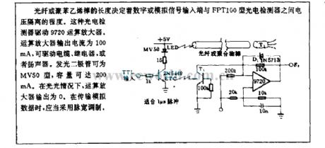
The length of optical fiber or polyrod decides the voltage isolated extent between digital or analog signal input terminal and FPT100 photoelectric detector. This photoelectric detector drives 9720 operation amplifier. The output current of operation amplifier is 100mA, it can drive cable, relay or loudspeaker. LED is MV50, its capacity can reach 200mA. If there is no light, the output of operation amplifier is 0. When it is transporting analog data, it shouldadpot PWM. (View)
View full Circuit Diagram | Comments | Reading(753)
Agricultural application pesticide light control black light lamp circuit
Published:2011/8/10 3:58:00 Author:Nicole | Keyword: Agricultural application pesticide, light control, black light lamp
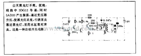
During the day, the black light lampdoes not light. At night, 3DG12 turns on, at the same time, 3AD30 produces oscillation, it is rised by transformer, then the black light lamp is lightened, it can attract pests, then it will use drug tank to poison the pests. It is an automatic switch circuit. (View)
View full Circuit Diagram | Comments | Reading(1014)
Up/down slope control circuit
Published:2011/8/10 4:05:00 Author:Nicole | Keyword: up slope, down slope, control circuit
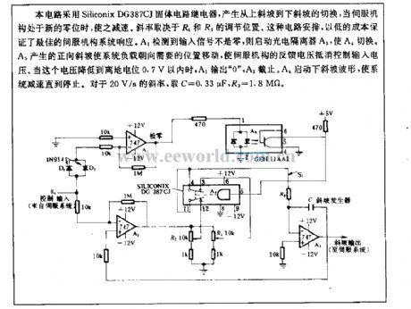
This circuit adopts Siliconix DG387CJ solid circuit relay to produce cut-over from up slope slope to down slope, when servo mechanism is in new zero, the circuit will slow down. The slope factor depends on the adjusting position of R1, R2. This circuit arrangement can ensure the best servo mechanism system response with low cost. The input singal detected by A1 is not zero, then starting the photoelectric isolator A3, to cut over A4. The system load is moved to the needed position by positive slope which is produced by A5, then the feedback voltage of servo mechanism will counteract the control input voltage. When this voltage drops to within 0.7V from ground potential, A1 outputs 0 , A3 cuts off. A4 starts down slope waveform, the system will slow down and until stop. For 20V/s slope factor, it takes C=0.33μF, R3=1.8MΩ. (View)
View full Circuit Diagram | Comments | Reading(1368)
Sound control, dimming commercial colored lamp control circuit
Published:2011/8/10 4:04:00 Author:Nicole | Keyword: sound control, dimming, color lamp
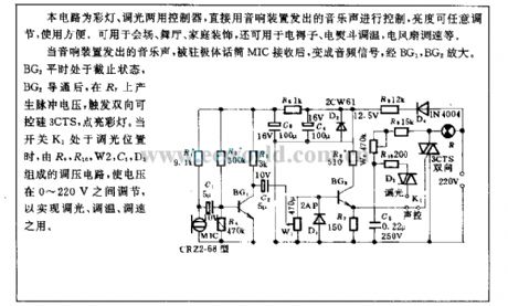
This circuit is colored lamp, dimming double-duty controller. It is direct conreolled by the musical sound of audio device, the brightness can be discretionarily adjusted, and it is convenient for using. It can be used in meeting place, dance hall, home decoration, and it also can be used in electric mattress, electric iron temperature adjustment, electric fan speed regulation and so on.
When the audio device sends out musical sound, after being received by electret microphone MIC, it will be changed into audio singal, it is amplified by BG1, BG2. BG2 is in off condition in normal times, after BG2 turning on, R7 will produce pulse voltage to trigger TRIAC 3CTS, and light up the color lamp. When switch K1 is in dimming position, the voltage is adjusted between 0~220V by the voltage regulation circuit which is composed of R9, R10, W2, C5, D3, to achieve dimming, temperature adjustment, speed regulation. (View)
View full Circuit Diagram | Comments | Reading(981)
Motor protector 6
Published:2011/8/10 4:11:00 Author:Nicole | Keyword: Motor protector
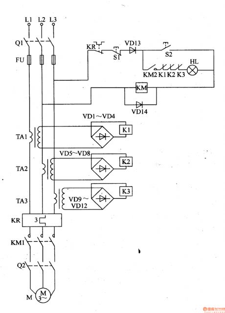
This motor protector circuit is composed of current transformer TA1-TA3, heat relay KP, rectifier diodes VDl-VDl4, relays K1-K3, starter button S1, stop button S2 and AC contactor KM, it is shown in the figure 8-42.
For some reasons, phase power is cut off, then this current transformer losses the work current, relay releases, the normally open contact is cut off, AC contactor KM cuts off and releases, then the motor M's work power is cut off, it can protect motor from damaging.
(View)
View full Circuit Diagram | Comments | Reading(831)
CS5330A, CS5331A stereo A/D transformation integrated circuit diagram
Published:2011/8/10 4:08:00 Author:Nicole | Keyword: stereo, A/D transformation
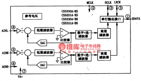
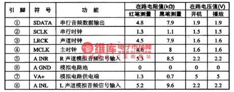
CS5330A, CS5331A are CMOS stereo players with 18 bit resolution which are produced by crystal company, they are widely used in DVD player.
1, functional characteristics
The sampling hold circuit, D∑A/D transformation circuit, digital one of ten filiter, reference voltage generator, serial output interface and other functions are integrated into a chip by CS5330A, CS5331A integrated circuit, it can change the input imitation audio singal into digital audio singal, the sampling frequency can be 32KHz, 44.1 KHz and 48KHz, the internal circuit block diagram of integrated package is shown as figure1, it adopts 8-foot packaging,the pin function and data ofintegrated circuitis shown in chart1.
Fugure1 the internal circuit block diagram of CS5330A, CS5331A integrated package is shown
chart1the pin function and data of CS5330A, CS5331Aintegrated circuit is shown (View)
View full Circuit Diagram | Comments | Reading(843)
16A thyristor control circuit
Published:2011/4/15 5:45:00 Author:May | Keyword: 16A, thyristor control
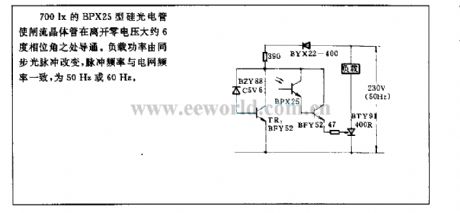
700lx BPX25 type silicon photocell can make thyristor breakover. The breakover place is about 6° phase angle leave to zero voltage . Load power is changed by synchronous optical pulse. Pulse frequency is 50Hz or 60Hz which is the same as grid frequency.
(View)
View full Circuit Diagram | Comments | Reading(1641)
100W sunset control circuit
Published:2011/12/1 21:02:00 Author:May | Keyword: 100W, sunset control
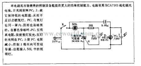
Comparing to controller equipment in the market, this circuit has larger control ability. The circuit adopts RCA7163cadmium sulfide photocell. The sunlight shines on PC2. It canmake it stay on low resistance. So it is not enough to light up the neon light. PC1 and neon light are in the same shade, so it is dark. When darkness is colsed, PC2 is in high resistance topromote neon lightand light up it. The light of neon light shines on PC1. The PC1's resistance is decreased. It can control three ends ofbidirectional thyristor to turn on. Then the lamp inserted in S0L is lit. (View)
View full Circuit Diagram | Comments | Reading(704)
Phase control circuit of Bi-directional thyristor without hysteresis
Published:2011/8/29 0:59:00 Author:Jessie | Keyword: Phase control , Bi-directional thyristor , without hysteresis
View full Circuit Diagram | Comments | Reading(1173)
Projector lamps thyristor AC regulating voltage circuit
Published:2011/8/29 1:13:00 Author:Jessie | Keyword: Projector lamps, thyristor, AC regulating voltage
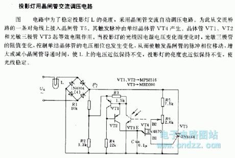
In order to steady projector lamps L's brightness, it uses thyristor AC regulating voltage circuit. So that it adds thyristor T5 to the AC bridge road. It's triggering pulse is produced by unijunction transistor VT4. The transistors VT1, VT2 and light activated triode VT3 has the same function. When projector lamps' light changing with power voltage's change,light activated triode's value changes, and the voltage phase which controls unijunction transistor changes too, so that the pulse triggering transistor's phase moves to increase or decreae the transistor conduction time, L voltage approximate remain, the brightness of the projector lamps also approximate remain, then the light keeps stability.
(View)
View full Circuit Diagram | Comments | Reading(1905)
Low-power AC-DC universal motor thyristor control circuit
Published:2011/8/29 1:08:00 Author:Jessie | Keyword: Low-power , AC-DC universal motor , thyristor control
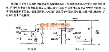
This circuit is used inAC/DC general motor thyristor speed adjustment occasions. The armature winding series isconnected to excitation winding, single-phase half wave phase shifting rectifier, and adjusting500Ω potentiometer can change thyristor's control Angle, so that speed is adjusted from 0 to maximum. This circuit is widely used in small household appliances such as blenders, sewing machines, hand drills and woodworking machinery.
(View)
View full Circuit Diagram | Comments | Reading(2471)
AC/DC general motors no hysteresis adjustable violations circuit
Published:2011/8/29 0:57:00 Author:Jessie | Keyword: AC/DC general motors, adjustable violations
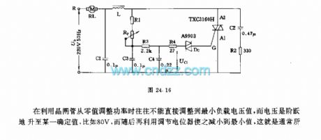
When ituses thyristor to cotrol power,theminimum load voltage always can't be directly from 0 , but voltage is stepped to a fixed value, for example, 80V can be reduced to the minimum valueby adjusting potentiometer, this is commonly said hysteresis effect. This circuit makes AC/DC general motors driving 300W, and adjusting potentiometer Rp can adjust the speed of motor.
(View)
View full Circuit Diagram | Comments | Reading(1042)
Intermittent oscillator control thyristor circuit
Published:2011/8/29 0:52:00 Author:Jessie | Keyword: Intermittent oscillator, thyristor
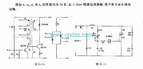
We can use intermittent oscillator T2 to control the anti parallel thyristor circuit, the width of its oscillation pulse is40 μs, pulse frequency is 3kHz. Switch S opens theoscillator, thyristor is always triggeredwhen the positive half cycle begins. In fact, the function of switch S can be taken by transistor T1.
(View)
View full Circuit Diagram | Comments | Reading(1645)
Electromagnetism thyristor control circuit
Published:2011/8/29 0:51:00 Author:Jessie | Keyword: Electromagnetism, thyristor
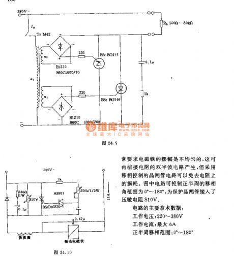
The vibration electromagnet in blender is general supplied by AC 220V. In order to makemixing, the electromagnet's pendulum pictureis often required uneven, it can be produced by former meet resistance's double half wave circuit. but the thyristor circuit controlled by phase shifting can avoidthe loss from resistance. The main technical parameters of circuit are: Working voltage: 220 ~ 380V; Working current: maximum 6A; The positive half cycle phase shifting range: 0 ~ 180 °.
(View)
View full Circuit Diagram | Comments | Reading(1327)
Series photoelectric couplers control thyristor switch circuit
Published:2011/8/29 0:48:00 Author:Jessie | Keyword: Series photoelectric couplers, thyristor switch
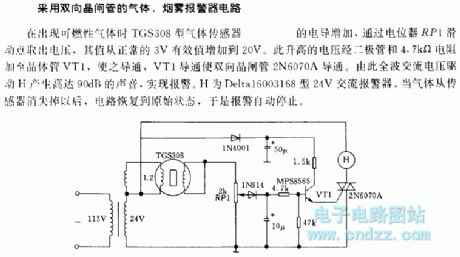
When the combustible gas appears, TGS308 gas sensor's conductivity increases,and thevoltagepassing potentiometer RP1's sliding point increases from normal 3V RMS to 20V. This increased voltage added to transistor VT1 makes2N6070A connect. The waveAC voltage driver H produces 90dB sounds torealize alarm. H is Delta16003168 24V AC alarm.After gases disappears from the sensor, circuit recoverys original state, so alarm automatically stops.
(View)
View full Circuit Diagram | Comments | Reading(797)
Below 3kw electromagnetic valve non-contact bi-directional thyristor connect circuit
Published:2011/8/29 0:41:00 Author:Jessie | Keyword: electromagnetic valve, non-contact, bi-directional thyristor
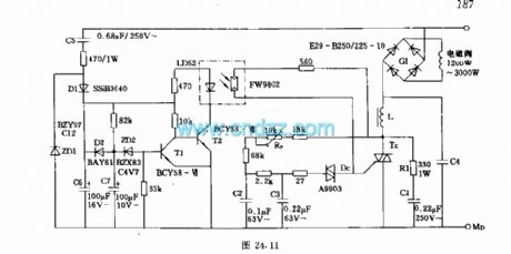
When the switchgets the power, light-emitting diode LD52 is connected. The photoconductor FW9802 which accessed to bi-directional thyristor'sdoor loop is decreased to 2.5kΩ, and it makes the loop's current enoughfor trigger thyristor's conduction, electromagnetic valve power supply. After 5s, RC charging circuit makes T1 connect, T2 cut off, light-emitting diode current interrupt, and then photoconductor's value increase, thyristor shut off, electromagnetic valve blackout.
(View)
View full Circuit Diagram | Comments | Reading(1400)
Bi-directional thyristor circuit with Flip-flop TCA780
Published:2011/8/28 22:52:00 Author:Jessie | Keyword: Bi-directional thyristor, Flip-flop
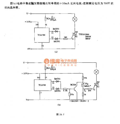
In figure a, integrated flip-flop can output double half cycle +50mA positive current to control the Bi-directional with 700 V rated voltage. Figure b is the reverse controlled current circuit. +15V Power supplycharges for0.22 μF capacitor through 10kΩ resistor, and the chanrging polarity is shown as the chart, then the transistor BC238 stops. When the pulse generated by the integrated trigger is added to the base of transistor by passing two diodes, the transistor is turned on, then the capacitor is grounded by the transistor, so the gate pole on thyristor generates a reverse trigger current to turn it on.
(View)
View full Circuit Diagram | Comments | Reading(1740)
Photoelectric transistors and two-way thyristor circuit controlled by AC voltage
Published:2011/8/28 22:33:00 Author:Jessie | Keyword: Photoelectric transistors, two-way thyristor, AC voltage
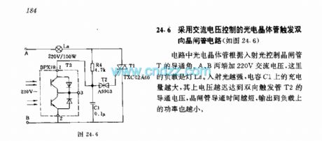
In this circuit, photoelectric transistor controls thyristor T's conduction angles by incident light. It adds 220V AC voltage on A,B, and La is the load. The stronger the incident light,the bigger thecharging on capacitorC1, the later voltage reaches Two-way trigger tube T2's conduction voltage, the shorter the thyristor's connection time, the lower the power of load.
(View)
View full Circuit Diagram | Comments | Reading(1146)
Two-way thyristor circuit integrated flip-flop TCA780
Published:2011/8/28 22:26:00 Author:Jessie | Keyword: Two-way thyristor, integrated flip-flop
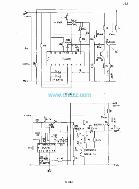
In this circuit, the control part and grid are segregated. The output pulse output by pin 15 of TCA780is amplified by trigger amplifier and added to pulse transformer primary winding. Secondary windings can supply 550μs triggering pulse, and the trigger current is 1A, andtrigger voltage is 2V.
(View)
View full Circuit Diagram | Comments | Reading(2682)
SIPMOS transistor control circuit using optical isolation
Published:2011/11/23 2:20:00 Author:May | Keyword: SIPMOS transistor, control, optical isolation
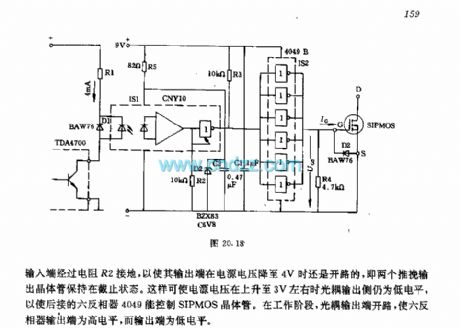
When TDA4700's output transistor is breaking over, optoelectronic isolator is breaking over. R1 is used for limitting the current, its value's sending and getting must make light coupled input end have about 4mA current. Diode D1 is used for limitting reverse over voltage when it is cut off. The input end of light coupling output gate circuit is connecting with ground through resistor R2 in order to make its output endbe open circuit when the power supply voltage drops to 4V. That is two push pull circuits's output transistor keeps on the cutting off state. It can make light coupling output to be low level when power supply voltage increases to about 3V in order to make back connecting six inverter 4096to control SIPMOS transistor. When it is working, light coupling end is open, it can make six inverter output end be in high level, but its output end is in low level. (View)
View full Circuit Diagram | Comments | Reading(1337)
| Pages:65/312 At 206162636465666768697071727374757677787980Under 20 |
Circuit Categories
power supply circuit
Amplifier Circuit
Basic Circuit
LED and Light Circuit
Sensor Circuit
Signal Processing
Electrical Equipment Circuit
Control Circuit
Remote Control Circuit
A/D-D/A Converter Circuit
Audio Circuit
Measuring and Test Circuit
Communication Circuit
Computer-Related Circuit
555 Circuit
Automotive Circuit
Repairing Circuit