
Control Circuit
Index 66
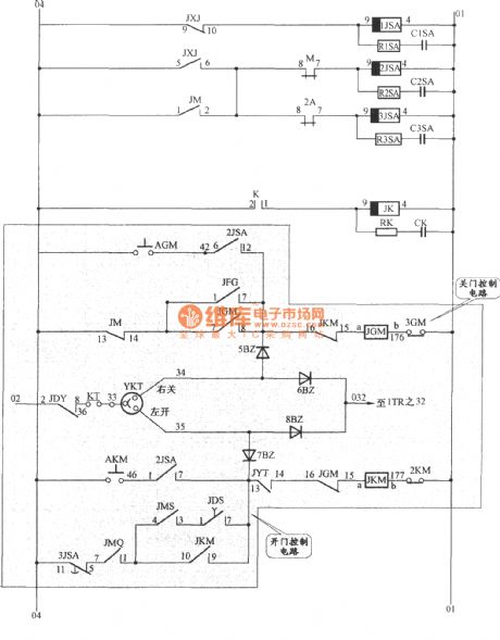
APM-81 elevator door driver control circuit
Published:2011/8/24 2:43:00 Author:Jessie | Keyword: elevator, door driver control
View full Circuit Diagram | Comments | Reading(1287)
Rice seeding bed high temperature alarm circuit
Published:2011/12/5 1:08:00 Author:May | Keyword: Rice seeding bed, high temperature alarm
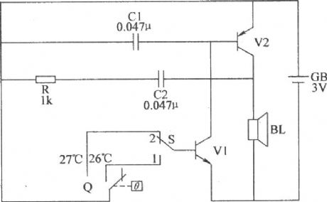
This rice seeding bed high temperature alarm circuit consists of electric hot thermometer Q, switch S, transistors V1, V2, resistor R, capacitors C1, C2, GB speaker BL and battery GB(V1, V2, and C1, C2, R, BL make up complementary oscillator circuit), and it isshown in the diagram. Component selection: R chooses 1/4W metal film resistor or carbon film resistor. C1 or C2choose polyester capacitors or monolithic capacitors. V1chooses 3DG6 or S9013 NPN silicon transistor; V2chooses 3AX81 germanium PNP transistors. BLchooses chose 0.25W, 812 electric loudspeaker. Qchooses fixed electric hot mercury thermometer. Schooses double-pole toggle switch. GBchooses two AA batteries. (View)
View full Circuit Diagram | Comments | Reading(1460)
Double-limit temperature alarm circuit 2
Published:2011/11/23 2:07:00 Author:May | Keyword: Double-limit, temperature alarm
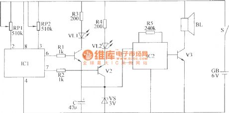
This double-limit temperature alarm circuit consists of temperature detection circuit control circuit, temperature indicating circuit and sound alarm circuit, as shown in the diagram.Component selection: R1 ~ R5 choose 1/4W carbon film resistor or metal film resistors. RP1 and RP2 chose small organic solid potentiometer. C choses electrolytic capacitors voltage is 10V. VL1 and VL2 are chose high-brightness light-emitting diodes φ3mm, VL1 is red, VL2 is green. VS chooses 1/2W, 3V voltage silicon diodes. V1 and V3 choose S9013 or C8050 silicon NPN transistor; V2 chooses S9015 or C8550 silicon PNP transistors. IC1 chooses TC602 temperature sensor integrated circuit; IC2 chooses S9015 or C8550 type silicon PNP transistor.BL chooses 0.25W, 8Ω micro-electric speaker. S chooses small single pole toggle switch. GB chopses 6V battery stack. (View)
View full Circuit Diagram | Comments | Reading(1299)
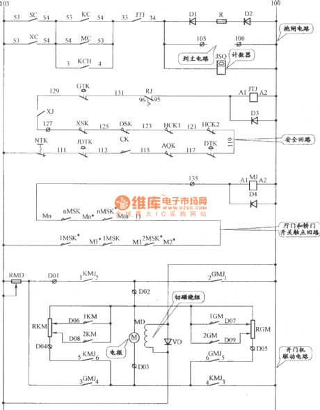
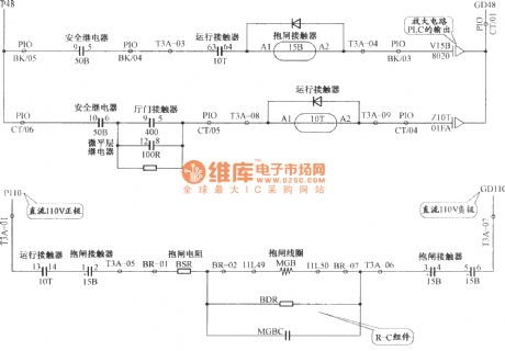
Shenyang sanyo AC two-speed elevator brake, gantry crane and security loop circuit
Published:2011/8/28 22:10:00 Author:Jessie | Keyword: Shenyang sanyo , AC two-speed, elevator brake, gantry crane , security loop
View full Circuit Diagram | Comments | Reading(1529)
Bi-directional thyristor gate pole limiting resistor adjustment circuit
Published:2011/8/28 21:20:00 Author:Jessie | Keyword: Bi-directional thyristor, gate pole , limiting resistor
View full Circuit Diagram | Comments | Reading(814)
Control circuit composed of six inverter and push pull circuit
Published:2011/11/23 2:25:00 Author:May | Keyword: Control, six inverter, push pull
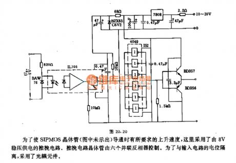
Here we adopt push pull circuit supply by 8V constant voltage in order to make SIPMOS transistor (it is not shown in the diagram) have the requiredraising speed when it is turned on. Push pull circuit transistor is controlled by six inverters in parallel connection. It adops optocoupler conponents in order to isolate with the level of input circuit. (View)
View full Circuit Diagram | Comments | Reading(1135)
Bi-directional thyristor control inductive load circuit
Published:2011/8/28 21:18:00 Author:Jessie | Keyword: Bi-directional thyristor, control inductive load
View full Circuit Diagram | Comments | Reading(1400)
Bi-directional thyristor AC voltage adjustment circuit
Published:2011/8/28 21:17:00 Author:Jessie | Keyword: Bi-directional thyristor, AC, voltage adjustment
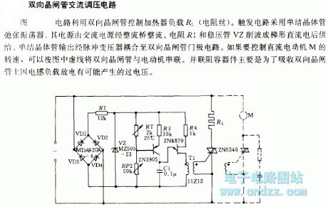
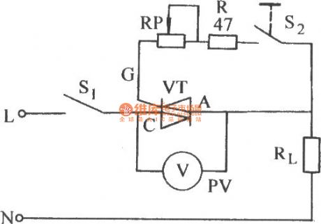
This circuit uses bi-directional thyristor to control heater load RL. Trigger circuituses a single junction transistor oscillator. It's supplied by AC power, resistor R1 and regulator tube V2. Single junction transistor output is sent to bi-directional thyristor circuit by bi-directional thyristor. If you want to control the speed of DC motor M, you can connect the two-way thyristor to the motor in series according to the dotted line in the figure. Parallel resistor is mainly used to absorb the possible over-voltage on the TRIAC caused by inductive load discharging. (View)
View full Circuit Diagram | Comments | Reading(1371)
LG Elevator band-type brake circuit
Published:2011/8/26 3:49:00 Author:Jessie | Keyword: Elevator, band-type brake
View full Circuit Diagram | Comments | Reading(910)
Starting protection circuit
Published:2011/11/22 0:15:00 Author:May | Keyword: Starting protection
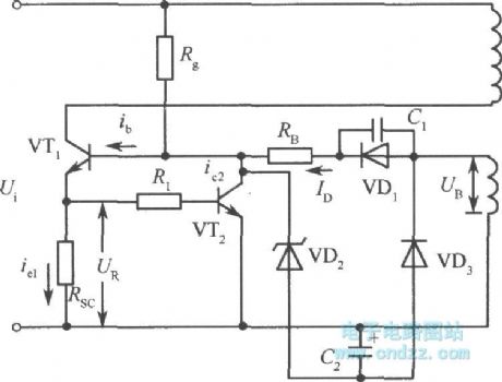
When the circuit is in the state of normal voltage regulation, controlling circuit can always keep VT1 base current in a fixed number. But when the power supply is breaking over, it will havea large starting current on transistor VT1. In order to prevent burning out this transistor VT1 by this current, we must take protection measure. The simplest protection is shown in the diagram, and it is added a resistor on the emitter of VT1.
When VT1 tube's current is enlarging, the voltage generatedby resistor Rsc is enlarging, VT1's base potential increases, driving current Id decreases. So VT1's base current is limited, VT1's collector current is limited to a fix number. We can know from the diagram, if drop voltage generated by switching transistor VT1's collector current on resistor Rsc is more than VT2's Ube2, VT2 is breaking over, it canmake VT1's base current divide a part, thereby it can make sure the collector current of VT1be less than protection value. (View)
View full Circuit Diagram | Comments | Reading(888)
Temperature measuring system circuit box circuit with thermocouple cold end temperature compensation and converter MAX6675
Published:2011/8/30 22:12:00 Author:Jessie | Keyword: Temperature measuring system, circuit box, thermocouple cold end temperature compensation, converter
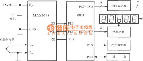
The temperature measuring system composedof MAX6675 is shown in the diagram. K thermocouple is connected to the T+ and T- of MAX6675, and the cold endof thermocouple is in the ground. Host chooses the 8051 microcontroller, and MAX6675 is the slave. From the P1.1 port of 8051, it sends serial clock to MAX6675,and P1.0 portis used to receive MAX6675 output temperature data. P1.2 port outputs low level to set CS 0. System is equipped withfive-position common cathode LED digital tube. Set decimal pointat ten behind, then wecan measure the temperature of 0~ +1024 ℃, and resolution is 0.1 ℃. P0 port is used to respectively connect decoding drive CD4511 and driver 74LS154. (View)
View full Circuit Diagram | Comments | Reading(1770)
Triple-digit display electronic timer circuit composed of NE555 and CD40110
Published:2011/8/30 1:58:00 Author:Jessie | Keyword: Triple-digit display , electronic timer
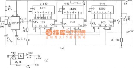
As shown in figure is electronic timing which is used for raider type cars. Car startups will launch timer,while car stops makes the timer stop.The value that car showsis the racing spending time. This circuit is composedof thecontrol switch and electronic timer. And electronic timerconsists of the time base generator and digital electronic counter. (A)is principle diagram; (b)is control switch circuit. IC1, IC2 and IC3are CD40110. (View)
View full Circuit Diagram | Comments | Reading(3534)
Countdown display timer circuit with NE556, CD40110
Published:2011/8/30 2:01:00 Author:Jessie | Keyword: Countdown display timer
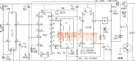
Digital display countdown timer can make people always see how much time left, it has certain practical value to some applications. As shown in figure, itis a digital display timing circuit, its structure is simple, and is easy to make. Its time-base unit adjustable. This circuit uses harmonic oscillator, which is composedof NE555 circuit as time base. Although the time precision is not quite high, it is economical and suitable. Full circuitis composedof adjustable time base signal generator, minus count, display and output signal control circuit etc. (View)
View full Circuit Diagram | Comments | Reading(3921)
Open/stop selecting function timer circuit with CD4541
Published:2011/8/30 2:11:00 Author:Jessie | Keyword: Open/stop selecting function, timer
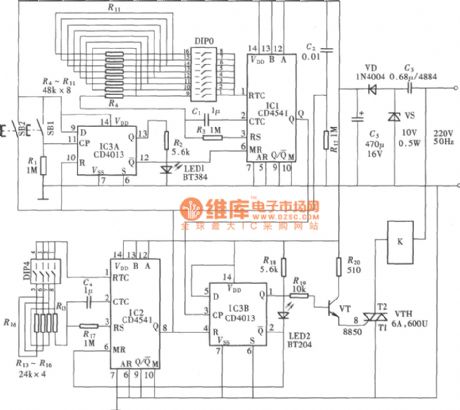
CD4541 is the main partof the timer. It can chooseto open firstly, or stopby switch. In circuit, timing time's adjustment is choosing by switch,the amount of the resistance between CD4541's pin1 and pin 2increasing and decreasing. Because resistance is decided as first, every resistoris fixed. So it is more convenient and accurate than the potentiometer to adjust timing time.The Circuit is composedofthe open/stop preset circuit, adjustable open/stop timing circuit, output control and executing circuit. (View)
View full Circuit Diagram | Comments | Reading(6170)
Division circuit with NE555
Published:2011/8/30 2:13:00 Author:Jessie | Keyword: Division
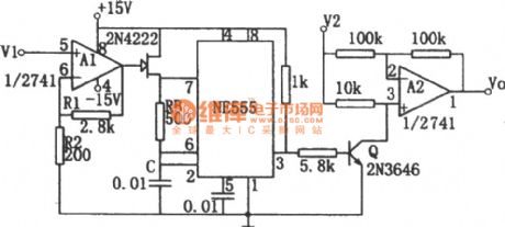
The circuit as shown is composedof thevoltage-frequency converterand amplitude modulator. Input V1 controls the resistance of mosfet 2N4222 by operational amplifier A1. Soit can change the oscillation frequency of no steady-state much harmonic oscillator. A2 is an input signal amplitude modulator. The input signal V2 is output after being modulated.It setsthe clip broken voltage of mosfetas Vp, if (1+R1/R2)=Vp, then the relationshipbetween output and input is: Vo=-V2/V1. The range of V1 and V2 is 0~10V. Output Vo is an average value, which can be gotten from filter or damping type voltmeter. (View)
View full Circuit Diagram | Comments | Reading(1392)
Circulation regularly reminded decoder circuit with CD4511
Published:2011/8/30 2:20:00 Author:Jessie | Keyword: Circulation regularly reminded decoder
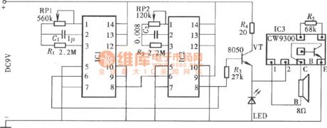
It uses two CD4541 connected in series to compose a circulation timer. The output terminal connected a sound circuitto form a regularly reminder circuit. This regularly reminder circuit has many uses, such as for the patient's care, regularly reminded medication, etc. Reminding sound circuit can be chosenaccording topeople's favoritemusic integrated circuit. This timer chooses musical CW9300 as sound circuit,and itscomposition is as shown. (View)
View full Circuit Diagram | Comments | Reading(2226)
Multistage timing program control circuit with CD4017, LM555
Published:2011/8/30 1:50:00 Author:Jessie | Keyword: Multistage timing, program control
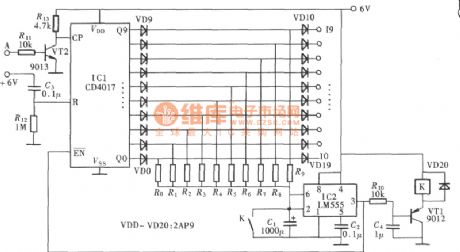
This program control circuit has tenth level program control output.Each level program can set timing time according to the actual need of work. Also, according to the actual control needs, it can be arbitrarily selectedin ten level. Circuit structure is simple, reliable, economical. Circuit components areas shown, there are only program pulse splitter and regular controller. (View)
View full Circuit Diagram | Comments | Reading(2119)
Power supply controller with high efficiency under various load condition
Published:2011/11/13 21:13:00 Author:May | Keyword: Power supply controller, high efficiency, under various load condition
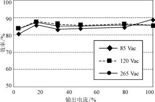
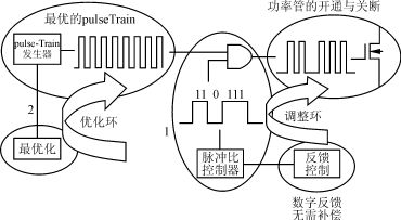
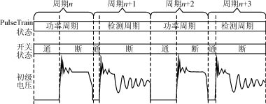
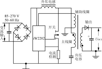
Aimed at all sorts of AC/DC and DC/DC conversion applications, iWatt company has developed three kinds of chip which can achieve pulse Train technology. The company also integrates some other functions in it. The functions are control logic, waveform analyzer, multiplexer, regulators and drives and so on. iW2101 is isolation DC / DC controller chip; iW2201 is AC / DC controller chip; iW2202 is single-chip type AC / DC controller with internal active PFC circuit.
Differ from other PFC program using complex circuits and common PWM controller, the FPC and regulated voltage of iW2202 are both offered by the initial feedback of single-stage single-switch topology, as shown in Figure 4. In the same application, the other PFC programs can make the justified voltage of capacitor over 1000V, but iW2202 program does not exceed 400V. It can not only reduce the stress of component and improve reliability, but also can achieve higher performance at lower cost systems.
(View)
View full Circuit Diagram | Comments | Reading(769)
Operational amplifier precision zero circuit (REF200) diagram
Published:2011/8/30 2:36:00 Author:Jessie | Keyword: Operational amplifier, zero circuit
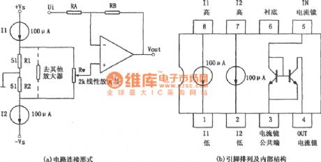
As shown in figure, the circuitis operational amplifier precision zero circuit. In some applications, it requires the disorder voltage of amplifierbeing small, and when the power supply voltage changes, thedisorder voltage is not affected. As shown in figure (a), the circuitcan realize this function. The circuit adopts double current source integrated chip REF200.The internal structure and pin arrangement of the chipare shown in figure (b). (View)
View full Circuit Diagram | Comments | Reading(1559)
Based on SPI bus high precision pressure testing system circuit
Published:2011/8/31 1:55:00 Author:Jessie | Keyword: SPI bus, pressure testing system
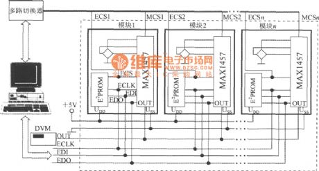
Using MAX1457, 27C64 each one piece,and matching a piezoresistive pressure sensor will constitute a pressure measurement module.N pieces ofpressure measurement modules and microcomputers, digital voltmeters canform the bus high precision pressure testing system based on SPI . The circuit is shown in diagram. It is a testing system composedof 6 transmissions, including two power lines, a simulation voltage output line, and three SPI interface lines. In addition, the multi-channel switch choosesmeasuring module andread-only memory through the MCS, ECS lines respectively. (View)
View full Circuit Diagram | Comments | Reading(762)
| Pages:66/312 At 206162636465666768697071727374757677787980Under 20 |
Circuit Categories
power supply circuit
Amplifier Circuit
Basic Circuit
LED and Light Circuit
Sensor Circuit
Signal Processing
Electrical Equipment Circuit
Control Circuit
Remote Control Circuit
A/D-D/A Converter Circuit
Audio Circuit
Measuring and Test Circuit
Communication Circuit
Computer-Related Circuit
555 Circuit
Automotive Circuit
Repairing Circuit