
Control Circuit
Index 71
Power-on sequence control switch (Load control module) circuit using LCE
Published:2011/10/20 22:24:00 Author:Rebekka | Keyword: Power-on sequence , control switch , Load control module, LCE
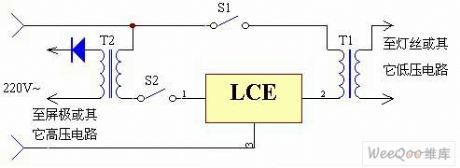
In some electronic device or some other device formed by the tubes, for several supply voltages, such as high pressure and low pressure should beturned on according to a certain order to start the low voltage. You may make a mistake if you are negligent. The use of LCE module can solve the problem. T1 is a low voltage transformer, its primary winding in series isin the LCE's ② feet; T2 is a high-voltage transformer, ofwhich the primary coil in series is in the LCE of ① feet. Normal start sequence should be: First pressing the switch S1, after a while, the vacuum tube filament ispreheating, and then pressing the switch S2. If the operation is in a reverse order, pressing the switch S2 make the circuit stop work, so you can ensure that procedures are correct. (View)
View full Circuit Diagram | Comments | Reading(932)
Photosensitive fuel gas annunciator circuit
Published:2011/10/23 21:56:00 Author:May | Keyword: Photosensitive, fuel gas, annunciator
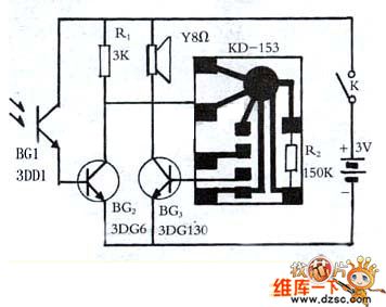
Fule gas can cook dinner and heat up water. During cooking process, thesoup overfolws, it's easy to put out , andfuel gas leak indoorcan cause a loss to life and property. Installing a fuel gas annunciator can avoid accident effectively.
Making material
3K, 150K 1/8 carbon-film resistor , one KD-153 music IC chip, one 3DDPhoto-Transistors, triode 3DG6, 3DG130, one8Ω speaker, switch, two dry batteries with battery clamp.
Working principle
When gas-cooker works normally, the annunciator is in the state of standby work. DG1 photistor receives flame shine, itpresents low resistance, BG2 breakovers, music vocal chip is in low level, speaker is not vocal. Once gas-cooker sudden dies out, photistor loses shine, its essential resistance increases, BG2gets saturation to close. (View)
View full Circuit Diagram | Comments | Reading(799)
Password Electronic Switch Circuit Diagram
Published:2011/10/23 20:58:00 Author:May | Keyword: Password Electronic Switch
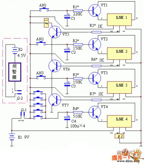
The working principle of this device is shown in the diagram. This password electronic switchhas three unlock buttons, and it also has the timelimiting circuit, error lock and electronic alarm circuit. It can make relay J1 excited pull in only by pressing unlock buttons AN1, AN2, AN3 correctly. The pick-up time is determined by the value of R1 and C1. In the diagram, transistors VT5, VT6, VT7 are cascaded into an AND gate circuit. When one of the three transistorsis cut off, the relay J1 will release. The five buttons AN1-AN8 are spliced into an OR gate logic circuit. It can cause the breaking over of transistor VT4. Then LSE's pin 1 and 2are broken over, and its pin 4 outputs high level, and relay J2 is excited and pulled in. Its locking time is determined by the value of R4 and C4.
(View)
View full Circuit Diagram | Comments | Reading(2265)
Wireless track warning module with wide frequency rolling code ( KB318/KB318R )
Published:2011/10/19 22:45:00 Author:Rebekka | Keyword: Wireless track , warning module , wide frequency, rolling code
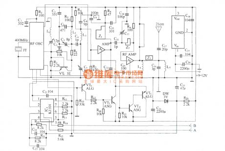
Remote control transmitter schematic.
Micro receiver circuit.
The circuitsare used for automobiles, motorcycles and other alarm feedback occasions that needs long-distance wireless BP machine-style. It adopts advanced technologies and devices with improved functionality. It is better than other similar products.It iscomposed of a wireless transmitter KB318T (or KB923T) and a key ring type micro receiver alarm KB318R (or KB923R).
(View)
View full Circuit Diagram | Comments | Reading(868)
Anti-theft wireless warning circuit diagram
Published:2011/10/20 2:05:00 Author:Rebekka | Keyword: Anti-theft wireless warning
Circuit is shown as above. It is composedof radio frequency (FM) radio transmitter and receiver circuit. When someone broke into the house, the wireless transmitters send FM signals and make the sound of breaking glass. You can listen itaway fromhundred meters, then the power amplifier drives speaker Bto emit sound.
(View)
View full Circuit Diagram | Comments | Reading(1284)
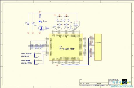
An air-conditioner control circuit
Published:2011/9/28 4:33:00 Author:Rebekka | Keyword: Air-conditioner control
View full Circuit Diagram | Comments | Reading(1052)
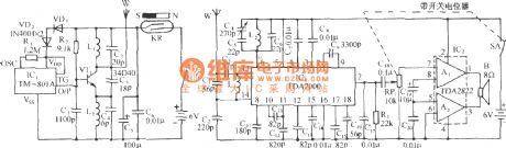
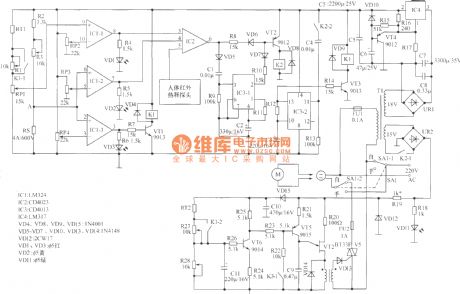
Fowl hatching electron constant temperature control circuit using TC621 temperature sensor
Published:2011/10/20 2:19:00 Author:Rebekka | Keyword: Fowl hatching , electron constant temperature , temperature sensor

Chicken egg incubation temperature requires 36 ~ 39oC temperature range. Temperature sensing integrated circuits uses TC621 temperature control circuit with fewer external components. The features are: Low cost, high reliability etc. You can set upper and lower temperature, and it is convenient to adjust. The circuit is shown as above. It consists of temperature sensor TC621, upper and lower limit , temperature indicator, relay controlling heatingcircuit,analog hen cackling sound circuit, audio amplifier circuit and the AC step-down rectifier circuit.
(View)
View full Circuit Diagram | Comments | Reading(1553)
Electrical apparatus start-stop circulatory timer circuit diagram
Published:2011/10/20 21:40:00 Author:Rebekka | Keyword: Electrical apparatus , start-stop circulatory timer
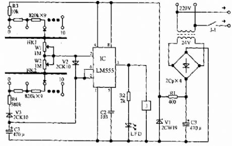
LM555 integrated circuit forms the basic duty cycle adjustable multivibrator. Discharge and charge circuit of C3 are connected to KH1, W1, KH2, W2 respectively in series for coarse tuning, fine-tuning the stop time. When the circuit starts to work, the power supply passes R3, HK1 series resistor and W1, V2 to C3, thenIC's pin 3 outputs high level. LED emitslight and the relay pulls in. Its contacts areconnected to the load. When the voltage on C3 rises to 2 / 3 supply voltage, IC flips, relay releases. Meanwhile, C3 passes V3, R4, HK2 and IC's 7 feet discharges power to the ground. When the voltage C3 drops to 1 / 3 supply voltage, IC flips and relay pulls in. So the cycle starts to work. Each block of HK1 and HK2 increase or decrease for 4.5 minutes. The adjustment range of W1, W2 is about 0 to 5 minutes. (View)
View full Circuit Diagram | Comments | Reading(2449)
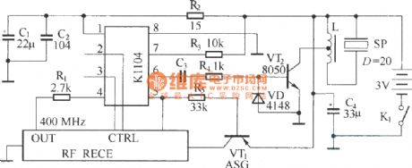
Goods anti-theft annunciator circuit diagram ( transceiver module composed of RCMlA/RCMlB)
Published:2011/10/19 22:18:00 Author:Rebekka | Keyword: Goods anti-theft annunciator
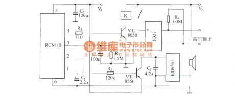
Emitter is composed of RCM1A and battery. Receiver is composed of receiver module RCM1B with double-delay function, high-voltage generator and the alarm circuit. (View)
View full Circuit Diagram | Comments | Reading(2153)
Eight-way wireless burglar alarm system circuit diagram
Published:2011/10/17 21:17:00 Author:Rebekka | Keyword: Eight-way wireless burglar alarm system

(a) shows the alarm monitoring and emission extension, KD9562 forms the alarm monitoring station launchesby 8 trigger terminals. The security monitoring circuit is composed of pyroelectric infrared detector module HL911L. When the situation occurs. HL911L's pin ① outputs high level. Then you can turnon the electronic switch to connect the internal circuit of TWH8778. TWH8778's pin ③ outputs high level, then the relay K is pulled in. Contaction switch KSwill makeemission component FDD5 work. (B) shows the host alarm receivingcircuit. When JDD5 gets the alarm signal sent by alarm extension. It will be demodulated. When JDD5 receives the alarm signal sent by the police station. The signal output by the output terminal is audio signal. It will make alarm sound through speaker. (View)
View full Circuit Diagram | Comments | Reading(1818)
Low frequency high frequency filter circuit diagram
Published:2011/10/21 2:07:00 Author:Rebekka | Keyword: Low frequency filter, high frequency
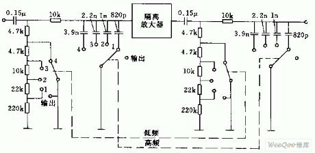
Figure (a) circuit is composed of RC filter with two cascaded parts. It is connected a isolation amplifier between them(such as emitter-follower). Low frequency - high frequency filter adjusts the performance curve by no-load output. It is shown as (b). fu = 40Hz, fu = 11KHz. (View)
View full Circuit Diagram | Comments | Reading(988)
Sequential timer circuit composed of 556
Published:2011/10/20 22:37:00 Author:Rebekka | Keyword: sequential timer
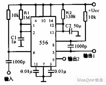
The diagram of sequential timer circuit composed of 556 is shown as above. 556 is a dual timer. The first timer output 1 passes 0.001μF coupling capacitor, then it isadded to the pin 8 of second timer's input end. The total delay is equal to two extension, 1 = 1.1 (R1C1 + R2C2). The wire connected to pin 6 is grounded, then the first timer can be turned on. (View)
View full Circuit Diagram | Comments | Reading(4955)
Two light control relay circuit diagram
Published:2011/10/18 3:25:00 Author:Rebekka | Keyword: Two light control relay
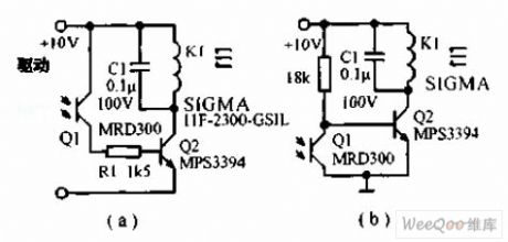
Two light control relay circuit is shown as below. The circuit is a simple light control relay. The relay operating current is 5mA, resistance is2300Ω. The phototransistor sensitivity of the photoelectric conversion is 4μA/ft/cd, if the brightness is 125ft / cd, the relay can work. (A) circuit is the light relay power circuit, (b) circuit is the light relay power circuit. (View)
View full Circuit Diagram | Comments | Reading(1063)
Infrared heat release probe automatic controller circuit diagram
Published:2011/9/27 1:43:00 Author:Rebekka | Keyword: Infrared heat release probe, automatic controller
The controller is used for the fan as automatic controlling. The role is to make the air flow, then the body's sweat is evaporate quickly and absorbs body heat to make people feel cool. In fact, people's feeling is not only determined by the temperature, when air is relative humidity, although temperature is not too high, people will still feel hot, so the relative humidity can not be ignored. In addition, the controller shown as the chart considers the temperature, but also it takes into account the relative humidity. When the relative humidity is below 70%, the temperature is above 30 ℃ and in the control range, the fan will start automatically. (View)
View full Circuit Diagram | Comments | Reading(1101)
Infrared alarm switch circuit diagram
Published:2011/9/26 22:15:00 Author:Rebekka | Keyword: Infrared alarm switch
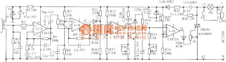
The figure shows the infrared alarm switch circuit. It uses the most popular domestic and international human pyroelectric PIR sensor as the signal detector. It has a high sensitivity, the detection range is up to 10m or more, the depression angles is up to 86 degrees, horizontal viewing angle is up to 120o. It is only sensitive to the specific wavelength infrared light that released by human body, so it has a minimal malfunction. When someone walks in the detection region in 0.3Hz ~ 3Hz frequency. It can give birth to weak signal sense. It is amplified by the UA, UB two-stage and outputs strong signal of 0.5V ~ 5.5V from the U-B7 feet. VD1, VD2, R10 ~ R13 and UC form the threshold comparator. The signal voltage induced by PIR can be positive or negative, so the U-B7 pin outputs voltage can be positive or negative (in terms of center voltage 3V). When the voltage on C8 is less than 13 feet (1V), the pin 14 has no output. Thyristor turns off, the lights automatically turn off. People sleep at night or when there is no one at home, you can turn off the switch S. If there is a thief sneaked into the detection region, the lights will be accompanied by ringing. It can scare away the thief, played the role of security. (View)
View full Circuit Diagram | Comments | Reading(3192)
Infrared delay light switch circuit diagram
Published:2011/9/27 1:33:00 Author:Rebekka | Keyword: Infrared delay light switch
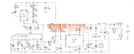
KA2184 infrared receiver integrated circuit ismade in the Korean. The performance, parameters and pin functions are identical with the CX20106.They can be directly used interchangeably. Since the circuit uses infrared reflective circuit structure. So infrared transmitter and receiver need to be installed in the same direction and in the same plane. It makes the transmitter and the receiver become integrated structure, and they use the same power supply. This work style also happens to meet the circuit standard. Such as long-term, short work of working state. In this circuit, it uses multivibrator composed of the NE555 as infrared emission tube drive circuit. (View)
View full Circuit Diagram | Comments | Reading(1326)
Bell alarm circuit diagram
Published:2011/9/26 22:05:00 Author:Rebekka | Keyword: Bell alarm circuit
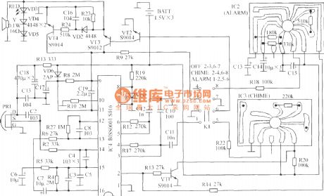
SNS-200P1 is the human body pyroelectric infrared alarm bell. SNS-200P1 uses three 5# batteries, portable design is ideal for alarm products. When the function switch isin the OFF position, the power off; In the CHIME position, it can be used for doorbell, when someone approaches, it will make ding-dong sound; In the ALARM position, it can be used as alarm, when some people close to the sound,thethe warning will be issued. The entire circuit is composed of body infrared detection sensor, the body infrared signal processing circuit, alarm audio circuits and audio amplifier circuit. (View)
View full Circuit Diagram | Comments | Reading(1926)
The circuit diagram of AC zero passage trigger solid relay
Published:2011/9/15 22:51:00 Author:Rebekka | Keyword: AC zero passage, trigger solid relay
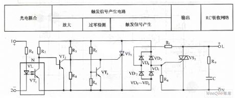
Zero-triggered communication solid-state relay electrical appliance circuit diagram. (View)
View full Circuit Diagram | Comments | Reading(1192)
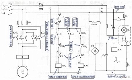
Motor fixed direction rotation control circuit diagram
Published:2011/9/15 22:53:00 Author:Rebekka | Keyword: Motor , fixed direction rotation, control circuit
View full Circuit Diagram | Comments | Reading(748)
Pulse phone 160168 controller circuit diagram
Published:2011/10/18 3:28:00 Author:Rebekka | Keyword: Pulse phone , controller
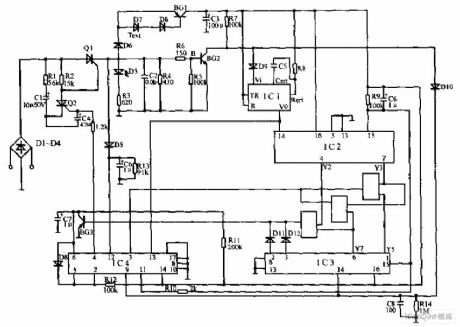
Pulse telephone 160 168 controller circuit is shown as above, the controller can be installed on the phone or on the switchboard of the trunk. It can effectively prevent the others to freely dail 160, 168. D1 ~ D4 use 1N4004, the rest diode use 1N4008. Q1, Q2 use BT169D; BG1 uses 5401, BG2 uses 9014; Resistor uses 0.125W metal resistor; IC1 is CC4098. IC2, IC3choose CD4017. IC4 is CD4066. The controller is connected in series with the phone between the city telephone line and the telephone line. (View)
View full Circuit Diagram | Comments | Reading(1818)
| Pages:71/312 At 206162636465666768697071727374757677787980Under 20 |
Circuit Categories
power supply circuit
Amplifier Circuit
Basic Circuit
LED and Light Circuit
Sensor Circuit
Signal Processing
Electrical Equipment Circuit
Control Circuit
Remote Control Circuit
A/D-D/A Converter Circuit
Audio Circuit
Measuring and Test Circuit
Communication Circuit
Computer-Related Circuit
555 Circuit
Automotive Circuit
Repairing Circuit