
Control Circuit
Index 72
Four-channel switch circuit diagram
Published:2011/10/18 3:25:00 Author:Rebekka | Keyword: Four-channel switch
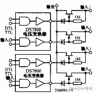
Four-channel switch circuitis shown as the chart, 2N4091 Junction FET power gives each group less than 30Ω on-resistance and a small turn-off leakage current. DS7800 voltage converter provides 10 ~ 20V gate drive voltage to junction field effect transistor, and it is compatible with DTL and TTL circuits. (View)
View full Circuit Diagram | Comments | Reading(1199)
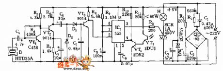
Interruptible infrared control circuit diagram
Published:2011/9/26 21:48:00 Author:Rebekka | Keyword: Interruptible infrared control
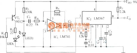
LM567 is a PLL audio decoding circuit.
(View)
View full Circuit Diagram | Comments | Reading(1186)
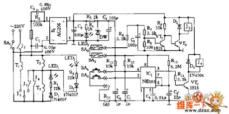
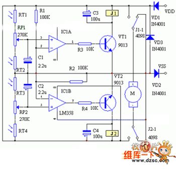
Infrared sensor automatic sprinkler control circuit diagram using BISS0001
Published:2011/9/26 21:25:00 Author:Rebekka | Keyword: Infrared sensor, automatic sprinkler control
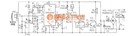
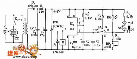
It includes the head of pyroelectric infrared sensor, infrared sensor application specific integrated circuit and the light control circuit composed of external components, and relay control circuit, music voice circui and AC rectifier buck circuit. When there is pedestrian access to the detection area of pyroelectric infrared sensor (PIR). PIR detects the infrared signal radiated by human body. The signal will be converted to low frequency (0.5 ~ 9Hz) signals. The signal will be added to the input op amp (14 feet) of BISS0001. The signal is amplified, filtered and information processed. Then the signal at output terminal 2 feet output a certain delay of the high output control signals. Add the control signal to VT1 relay control circuit to pull in the K1, and its contacts K1-1 closes, the electromagnetic valve W gets water sprays. (View)
View full Circuit Diagram | Comments | Reading(4111)
Inversion sampling and maintaining circuit diagram
Published:2011/9/13 2:35:00 Author:Rebekka | Keyword: Inversion sampling , maintaining
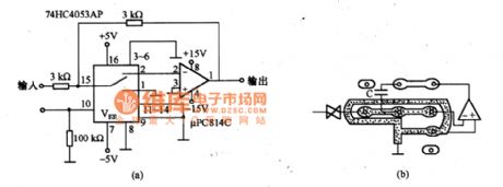
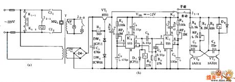
Figure (a) is the inversion sampling and maintaining circuit diagram. When it is maintaining, the op amp's inverting input is in high impedance. The potential of this part is 0. It uses the potential as the protection ring. The circui is shown in figure (b). (View)
View full Circuit Diagram | Comments | Reading(972)
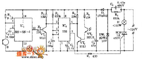
Multi-control switch circuit diagram 5
Published:2011/9/16 0:57:00 Author:Rebekka | Keyword: multi-control switch
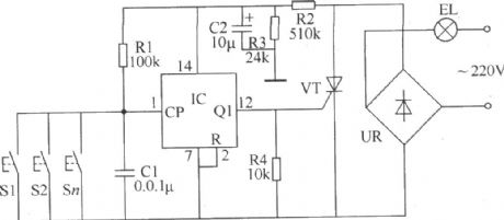
Multi-control switch circuit diagram.
This example describes the multi-control switch whichcan be used to control lights or low-power single-phase AC motor. The control switch circuit of the step-down circuit and control circuit, and it isshown in Figure 34.
Components selection. R1, R3 and R4 select 1/4W metal film resistors; R2 uses 1/2W metal film resistors. C1 selects monolithic capacitors; C2 uses electrolytic capacitor with thevoltage in 16V. IC uses 7-bit binary counter CD4024 IC. If the controlled lightisbelow 100W, the UR and VT can choose 1A, 400V reactor and thyristor rectifier bridge; If the single-phase AC motors is controlled under 1kW, the UR and the current capacity of VT should be 6 ~ 10A.
(View)
View full Circuit Diagram | Comments | Reading(1540)
Temperature monitoring alarm equipment circuit
Published:2011/4/14 6:43:00 Author:may | Keyword: Temperature monitoring, alarm equipment
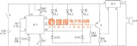
The temperature monitoring alarm equipment circuit introduced in this example has high , middle , low 3 gear temperature indication. It can send out alarm signal when the temperature is too high or too low. It can use in the occasion of big-arch shelter, greenhouse, etc which is needing temperature control.
This temperature monitoring alarm equipment consists of temperature monitoring/indication circuit and voice alarm circuit. The circuit is shown in the diagram.
Theoptions of components
R1~R4 chooses 1/4W metal-film resistor or carbon film resistor.
RP chooses compound film resistor or variable resistor.
VD1~VD3 all choose 1N4148 type silicon switching diode.
VL1~VL3 all choose Φ3mm LED
V chooses S8550 or 3CG8850 type silicon PNP transistor.
IC1 chooses ZH-3 type photometry application specific integrated circuit.
HA chooses DC electric magnetic buzzer with internal alarm voice source. (View)
View full Circuit Diagram | Comments | Reading(1020)
Magnetic amplifier control circuit diagram
Published:2011/10/16 22:24:00 Author:Ecco | Keyword: Magnetic amplifier control
View full Circuit Diagram | Comments | Reading(1502)
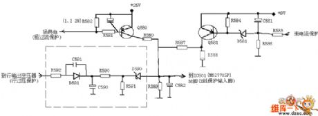
MX-5 movement protection schematic diagram
Published:2011/10/17 2:13:00 Author:Ecco | Keyword: movement protection
View full Circuit Diagram | Comments | Reading(766)
Timing control circuit diagram of vibrator
Published:2011/10/17 1:40:00 Author:Ecco | Keyword: Timing control , vibrator
View full Circuit Diagram | Comments | Reading(1703)
Homogeneous flow controller circuit diagarm of parallel module
Published:2011/10/17 2:06:00 Author:Ecco | Keyword: Homogeneous flow controller, parallel module
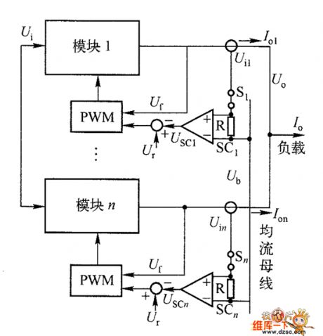
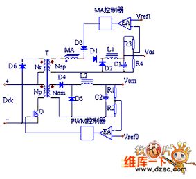
Figure 1 shows the automatic homogeneous flow block diagram composed of number of DC / DC converter modules connected in parallel, and the system's outer loop is the current-control loop, inner loop is the voltage control loop.
(View)
View full Circuit Diagram | Comments | Reading(905)
Photosensitive voice switch circuit with locking in the day
Published:2011/10/14 2:47:00 Author:Ecco | Keyword: Photosensitive voice switch
View full Circuit Diagram | Comments | Reading(935)
Multi-function power-saving lighting outlet control circuit
Published:2011/10/14 3:28:00 Author:Ecco | Keyword: Multi-function , power-saving lighting, outlet control
View full Circuit Diagram | Comments | Reading(791)
Yuanshan boiled water controller circuit
Published:2011/10/14 3:22:00 Author:Ecco | Keyword: Yuanshan , boiled water controller
View full Circuit Diagram | Comments | Reading(830)
Optical double-control delay lamp circuit (1)
Published:2011/10/14 2:45:00 Author:Ecco | Keyword: Optical double-control , delay lamp
View full Circuit Diagram | Comments | Reading(807)
Optical double-control delay lamp circuit (2)
Published:2011/10/14 2:44:00 Author:Ecco | Keyword: optical double-control , delay lamp
View full Circuit Diagram | Comments | Reading(759)
The alarm circuit diagram of optical intensity controlling
Published:2011/9/15 21:27:00 Author:Rebekka | Keyword: alarm circuit, optical intensity controlling
The circuit is available for hunters, fishermen go for a job at dawn. By flashlight or inside lights this circuit can betriggered. So it can be used as fire and burglar alarm circuit. Only when the lights die out, the alarm will stop. (View)
View full Circuit Diagram | Comments | Reading(1561)
Solar automatic tracking controller circuit diagram
Published:2011/9/15 21:54:00 Author:Rebekka | Keyword: Solar automatic tracking controller
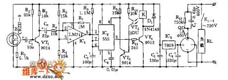
There are 2 kinds of solar automatic tracking controllers. One is Schmitt trigger light control composed of a light sensor and a Schmitt trigger or monostable trigger. The second one is usingtwo light sensors and two comparators to form two light-control motors and controlforeward and reversing. As throughout the year, the strength of the sun in the morning and at noon changes in ambient light, and the range is enormous, the above two controllersare difficult to make large solar energy receiver track in the sun-weather season. The control circuit described here also includes two voltage comparators. Butthe input side of the light sensors is composed of two photosensitive resistors connectedin series. (View)
View full Circuit Diagram | Comments | Reading(6484)
Excess temperature alarm circuit diagram
Published:2011/9/15 22:32:00 Author:Rebekka | Keyword: Excess temperature alarm
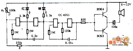
This circuitis composed ofa CMOS gate CC4011. It uses the ordinary thermistor for temperature measurement and it can emit sound, light and alarm. The two doors around the left side form the 2HZ controllable oscillator, and thetwo doors on the right formthe 400HZ controlled oscillator. When the temperature is normal, the partial-pressureof thermistor resistor RT and resistor R is lower than threshold voltage of NAND gate, two oscillators do not work. Once it is over temperature, RT is small enough, the first class NAND gate opens, the oscillator works, and the red and green light-emitting diodes alternating work, thenlthe oudspeaker emitssound. To save the transistor,it requires two tubes with the β> 150. (View)
View full Circuit Diagram | Comments | Reading(1301)
Low current anti-theft alarm circuit diagram
Published:2011/9/15 22:35:00 Author:Rebekka | Keyword: Low current anti-theft alarm
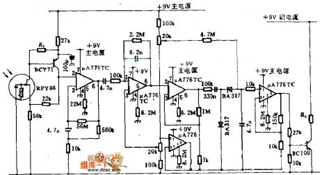
Detector RPY86 is produced by Mullard, and it only makes responses to the wavelength which isgreater than 6μm. It has not any response to thebackground light caused by sunlight and the sun. In order to gather infrared light onto the detector, it uses cheap mirror instead of Lens. μA776 is a programmable operational amplifier, and its bias current is only 300μA, which can be recharged by a small battery. Ra should be selected carefully, and the first operational amplifier's input voltage is 2 ~ 6V. Only when the thieves walk around the monitored area, the changes caused by the incident light will makethis circuit pull the alarm relay RL. (View)
View full Circuit Diagram | Comments | Reading(1621)
Missing pulse alarm circuit diagram
Published:2011/9/15 1:56:00 Author:Rebekka | Keyword: Missing pulse alarm
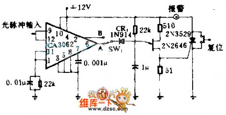
The circuit is used to detect the missing optical pulse or shortage of goods on the conveyor belt. CA3062 combination of detectors and amplifier can detect optical pulse which is synchronous with 60HZ power frequency . When switch SW1 is at A, every pulse has a interval of 16.7ms. It makes 2N2646 unijunction transistor reset at 20ms timing network. It avoids unijunction transistor triggering and triggers controlled rectifier. The alarm will be connected. When the SW1 at B, the circuit stops the detection of steady-state beam. It only alarmsat uninterrupted time.
(View)
View full Circuit Diagram | Comments | Reading(1501)
| Pages:72/312 At 206162636465666768697071727374757677787980Under 20 |
Circuit Categories
power supply circuit
Amplifier Circuit
Basic Circuit
LED and Light Circuit
Sensor Circuit
Signal Processing
Electrical Equipment Circuit
Control Circuit
Remote Control Circuit
A/D-D/A Converter Circuit
Audio Circuit
Measuring and Test Circuit
Communication Circuit
Computer-Related Circuit
555 Circuit
Automotive Circuit
Repairing Circuit