
Control Circuit
Index 70
Door controlling switch circuit
Published:2011/10/18 22:07:00 Author:Ecco | Keyword: Door controlling switch
View full Circuit Diagram | Comments | Reading(786)
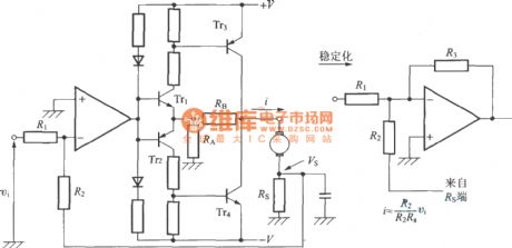
The current controlling circuit by discrete transistor
Published:2011/11/1 21:14:00 Author:Ecco | Keyword: current controlling , discrete transistor
View full Circuit Diagram | Comments | Reading(906)
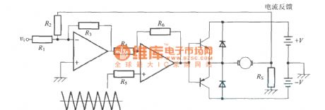
PWM current controlling circuit
Published:2011/11/3 3:15:00 Author:Ecco | Keyword: PWM current controlling
View full Circuit Diagram | Comments | Reading(938)
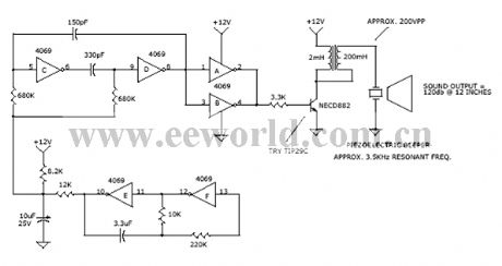
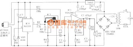
120db sweepfrequency alarm circuit
Published:2011/11/3 2:46:00 Author:Ecco | Keyword: 120db , sweepfrequency alarm
View full Circuit Diagram | Comments | Reading(1273)
Analog temperature controller circuit
Published:2011/11/1 22:19:00 Author:Ecco | Keyword: Analog temperature controller
View full Circuit Diagram | Comments | Reading(2067)
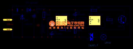
Timing automatic AC shutdown circuit diagram
Published:2011/10/31 2:22:00 Author:May | Keyword: Timing , automatic AC shutdown
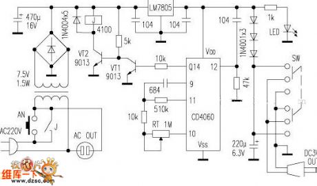
Befeore it gets power, the timing clock generator is reset by the capactor of the pin 12 of IC, and the various output stages are in low potential. Because out-port Q14 outputs low level, the triode VT1 closes, the VT2 is breakover, relay J gets the electricity, then the contacts pull in. AC OUT is the AC output socket, which may serve as the head light, miniature ceiling fan and other AC electric appliances without timing device. The CD4060 integrated circuit has the 14-level binary counting/divider with clock pulse oscillator. Adjusting potentiometer RT can change the fixed time, and the timing time is approximately between 20 second ~4.5 hour.
(View)
View full Circuit Diagram | Comments | Reading(1141)
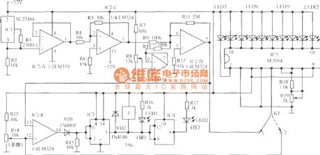
Electronic self-locking interlock switch circuit diagram
Published:2011/10/31 3:32:00 Author:May | Keyword: Electronic self-locking interlock switch

Switch's core component is the four operational amplifier LM324, after the ingenious design, each operational amplifier has the twofold function like the voltage comparator and the Schmitt trigger. The voltage applicable scope is wide, and the files may be designed willfully, if it adds a neutral gear, it can be used as the overall reset, when it is used with the digital circuit, they can use the same power source, and the switch's input, output level conforms to digital circuit's connection level, because operational amplifier has high input impedance, the switch's input current is small, it may use the light touching switch. The conductive rubber, thin film switch makes the pressing key. (View)
View full Circuit Diagram | Comments | Reading(2403)
Electronic light touch switch circuit
Published:2011/10/27 21:10:00 Author:May | Keyword: Electronic light touch switch
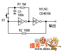
Bistable circuit is a kind of circuit we often use. It is always usedas one-button controlling switchin various circuits.
Working principle: If N1 input end starts in high level, then N2 output also is in high level, then R2 makes the circuit output the high level stably. At this time, because the N1's output port is in low level, therefore C1 discharges by R1. After pressing down S1, N1's input end changes to the low level, the N2's input rises, the N2's output changes to the low level, then the circuit reverses to output the low level stably, and C1 charges by R1. If pressesing S1 again, the circuit returns to another steady state. (View)
View full Circuit Diagram | Comments | Reading(1163)
Eggs hatching incubator 2
Published:2011/10/18 3:45:00 Author:Ecco | Keyword: Eggs hatching incubator
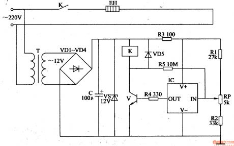
The eggs hatching incubator circuit is composed of the power supply circuit and temperature control circuit, and it is shown in Figure 4-5. Power supply circuit consists of the power transformer T, rectifier diodes VDl-VM, filter capacitor C and zener diode VS. Temperature control circuit consists of the resistors Rl-R5, potentiometer RP, diode VD5, temperature sensor integrated circuit IC, transistor V, Relay K and electric heater EH. Rl-R5 select the 1/4W metal film resistors or carbon film resistors. RP uses the small synthetic membrane potentiometer or multi-turn potentiometer. VDl-VD5 choose 1N4007 silicon rectifier diodes.
(View)
View full Circuit Diagram | Comments | Reading(3145)
Remote control load protection circuit diaram
Published:2011/9/26 21:55:00 Author:Rebekka | Keyword: Remote control load protection
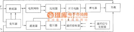

Remote control block diagram of the load protection.
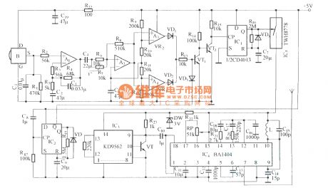
Remote control transmitter.
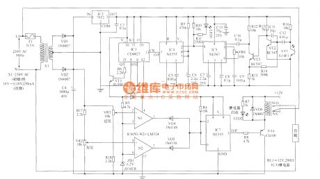
Remote control receiver and load protection circuits.
Load protection's main functions are: (1) When the power supply voltage is too low or too high, the load will be off automatically; (2) When the power supply voltage is restored, the load power will be connected automatically; (3)Ot provides powerfor normal indication, When the voltage is too low or too high, the light will turn off; (4) Using remote control to remote control power.
(View)
View full Circuit Diagram | Comments | Reading(1354)
Pyroelectric infared detection wireless alarm circuit diagram
Published:2011/9/26 22:02:00 Author:Rebekka | Keyword: Pyroelectric infared detection , wireless alarm
View full Circuit Diagram | Comments | Reading(914)
Human infrared thermal release alarm
Published:2011/9/26 22:01:00 Author:Rebekka | Keyword: Human infrared, thermal release alarm

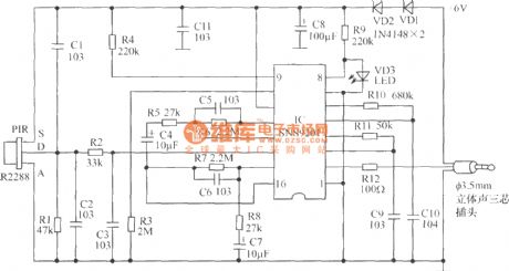
Human infrared thermal release alarm can receive the heat releasing infrared ray issued by the body during the day or night, then it willgive the sound and light alarm. It is ideal for electronic guard. Working principle: The circuit uses imported IC, general-purpose sensor control circuit, high input impedance operational amplifier, it consists of the timer, the timer latch, and the operating voltage is 3.5V ~ 5V, and quiescent currentis 60μA. It uses 3 ~ 4 1.5V batteries or 6V ~ 12V rectifier. Pyroelectric infrared sensor RIP09 TL receives body heat release signal. The signal will be amplified by the first stage op amp in IC. Then it will be amplified and coupled by the second level of C6 amplifier. Then it will be sent to built-in comparator to have bidirectional amplitude discrimination. R2, C2 are delay control. If you need longer hours of work, you can increase the R2's resistance or the capacitance value ofC2, the circuit is set to 3s ~ 4s.
(View)
View full Circuit Diagram | Comments | Reading(2411)
Electronic dog alarm circuit diagram
Published:2011/9/27 21:03:00 Author:Rebekka | Keyword: Electronic dog alarm
(1)Thepartschematic of infrared sensor electronic dog alarm probe.
Electronic dog alarm is composed of pyroelectric infrared sensor and alarm control speaker.
Alarm controlling speaker's principle diagram. (View)
View full Circuit Diagram | Comments | Reading(1580)
Time controller circuit diagram using CD4060
Published:2011/10/20 21:20:00 Author:Rebekka | Keyword: time controller
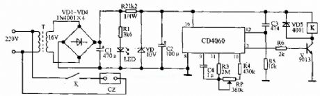
When the circuit gets power, it is connected instantaneously, and R5, C3 constitutes the differentiating circuit to guarantee delay time from zero. Under oscillator signal's influence, CD4060's internal counter starts to work, 3 feet is the 14th level counter's out port, if it makes 3 feet switches to the high level from low level, it needs t=213×2.2KC (second), and the low voltage of pin 3 causes the triode V closure. When delay time reaches, pin 3 jumps to high level from low level, then V is saturated breakover after being current limited by R6, and relay K pulls in, then the load gets the electricity. This electric circuit's delay time can be adjusted in 2.1~4 hours. (View)
View full Circuit Diagram | Comments | Reading(2880)
Detection alarm circuit diagram composed of TWH9248/TWH9249
Published:2011/10/18 1:12:00 Author:Rebekka | Keyword: Detection alarm circuit
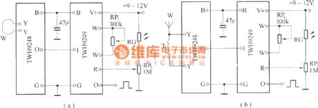
TWH9248/TWH9249 is a pair of microwave sensing components (also known as radar detectors). It is mainly used for movement detection of human body or object. The effective detection distance is 3-6 meters, voltage is 9-12V.
(View)
View full Circuit Diagram | Comments | Reading(1175)
Automatic exposure controller circuit using ER1211 ASIC
Published:2011/10/20 21:06:00 Author:Rebekka | Keyword: Automatic exposure controller , ASIC
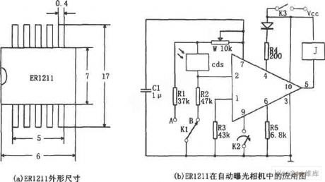
ER1211 is the automatic exposure controlling ASIC in the automatic camera. The pin arrangement is shown in Figure (a), ① is the supply voltage monitoring, ② is the illumination monitoring, ③ is grounding, ④ is illumination warning output, ⑤ is relay driving output, ⑥ is exposure time delay device, ⑦ is exposure delay input, ⑧Automatic focus control, ⑨ is exposure control, ⑩ is power Vcc. If illumination environment light is lower than limit (V2 ≤ V6-0.2V), ④ pin outputs low level, low-light warning light LED emits light. Linkage with the flash K-selector switch is opened at the receiving position A, the corresponding C1 passes W, R1 discharges, the exposure time (discharge time) is fixed, even if the flash automatic metering circuit does not work.
(View)
View full Circuit Diagram | Comments | Reading(787)
Ventilator auto-control circuit composed of μA555
Published:2011/10/20 20:58:00 Author:Rebekka | Keyword: Ventilator auto-control
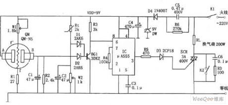
The circuit is composed of the AC step-down rectifier (VDD = +9 V), toxic and hazardous gas sensor head QM-N5, the temperature detection circuit Rt, bistable control circuit. QM-N5 is a gas sensory semiconductor device, Rt uses MF-51 NTC thermistor.
The resistance at the 2 ends of QM between A and B is larger. The potential of B is lower than 1V. It makes the D2, BG2 stop. 555 feet will be reset by the high level of ⑥. The low level output by pin ③ will stop SCR. The ventilation fan does not work.
When the concentrations of indoor harmful gases exceeds the allowable value, the resistance value of QM-N5 will rapidly decrease and the electric potential of B rises, the D2, BG2 will be conducted. (View)
View full Circuit Diagram | Comments | Reading(1639)
C192, 555, CD4028 automatic changing l0-block speed controller circuit
Published:2011/10/20 20:53:00 Author:Rebekka | Keyword: automatic changing, l0-block speed controller, 555
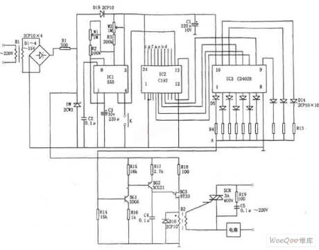
The circuit includes a clock signal generator IC1, counter IC2, decoder IC3, simultaneous phase-shifting circuit (BG1, BG2, BG3), SCR control circuit SCR, buck rectifier circuit. The step-down voltage is stabilized in (9 ~ 10.5) V. It provides power for the entire controller.
The clock signal generator is the multi-vibrator composed of IC1 (555), R2, R3, W1, W2, C3 and other components. The signal frequency depends on the charge and discharge time constant, and adjusting the W1, W2can change the signal frequency and duty cycle. The low-frequency square wave produced by IC1 is count pulse of IC2 and it will be added to the CP side (14 feet). (View)
View full Circuit Diagram | Comments | Reading(2170)
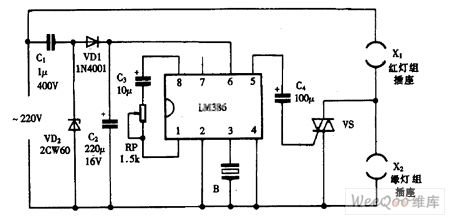
Using LM386 as dual-color music colored lantern controller circuit diagram
Published:2011/10/20 20:43:00 Author:Rebekka | Keyword: dual-color , music colored lantern , controller
View full Circuit Diagram | Comments | Reading(1291)
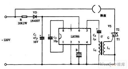
Using LM386 as music colored controller circuit diagram
Published:2011/10/20 20:41:00 Author:Rebekka | Keyword: music color lantern controller
View full Circuit Diagram | Comments | Reading(842)
| Pages:70/312 At 206162636465666768697071727374757677787980Under 20 |
Circuit Categories
power supply circuit
Amplifier Circuit
Basic Circuit
LED and Light Circuit
Sensor Circuit
Signal Processing
Electrical Equipment Circuit
Control Circuit
Remote Control Circuit
A/D-D/A Converter Circuit
Audio Circuit
Measuring and Test Circuit
Communication Circuit
Computer-Related Circuit
555 Circuit
Automotive Circuit
Repairing Circuit