
Control Circuit
Index 63
555 Timer Forms Simple PWM Motor Controller
Published:2012/9/5 20:35:00 Author:Ecco | Keyword: 555 , Timer Forms , Simple , PWM , Motor Controller
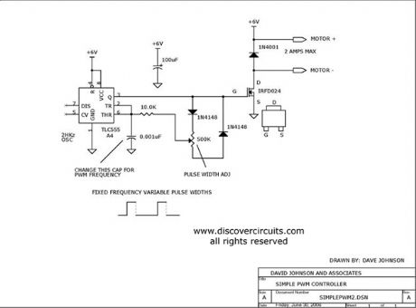
Using a CMOS version of the 555 timer, this circuit can be used to control the speed of a motor by adjusting the duty cycle of the pulses sent to the motor.
Source: discovercircuits
(View)
View full Circuit Diagram | Comments | Reading(4)
Voice-control music synchronized with lantern water controller circuit
Published:2012/9/4 22:03:00 Author:Ecco | Keyword: Voice-control , music synchronized , lantern water, controller
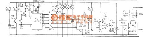
As shown in the figure, the circuit consists of voice circuit, four-phase pulse distributor/ driver, SCR trigger control circuit, music circuit and AC buck rectifier circuit. After the burst sound signal starts lantern, the music will play, Subsequently, the lantern will flow like water or chase with the melody and loudness size, and the music and audio loudness are faster; Conversely, water flowing velocity is slower. The lanterns changes synchronized with the main theme of the song.
(View)
View full Circuit Diagram | Comments | Reading(889)
Wire Security Loop Alarm
Published:2012/9/4 20:53:00 Author:Ecco | Keyword: Wire , Security , Loop Alarm

A wire loop is used to protect valuable objects in this alarm circuit. The circuit is powered by a 9v battery.
Source: discovercircuits (View)
View full Circuit Diagram | Comments | Reading(997)
ELECTRIC FIELD DISTURBANCE MONITOR - Alarm Discriminator + Battery Monitor
Published:2012/9/4 20:52:00 Author:Ecco | Keyword: ELECTRIC , FIELD DISTURBANCE MONITOR, Alarm Discriminator, + Battery Monitor
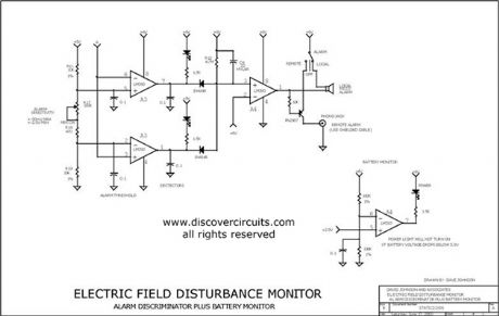
This schematic is the power supply and front-end sections of the field monitor that is discussed in more detail at Electric Field Disturbance Monitor. The system can detect human and animal motion by the electric fields they disturb.
Source: discovercircuits (View)
View full Circuit Diagram | Comments | Reading(10)
9v POWERED XENON PHOTOFLASH Controller
Published:2012/9/4 20:39:00 Author:Ecco | Keyword: 9v, POWERED, XENON , PHOTOFLASH Controller
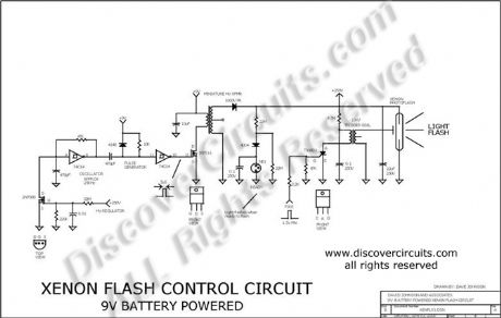
This 9v battery powered circuit is designed for remote control flash needs. A charge control circuit turns off the high voltage generator when the photoflash capacitor is fully charged. A neon lamp is included to indicate when the system is ready to flash.
Source: discovercircuits (View)
View full Circuit Diagram | Comments | Reading(1147)
ANOTHER VERY LOUD PIEZO ALARM BEEPER
Published:2012/9/4 20:21:00 Author:Ecco | Keyword: ANOTHER , VERY LOUD, PIEZO , ALARM BEEPER
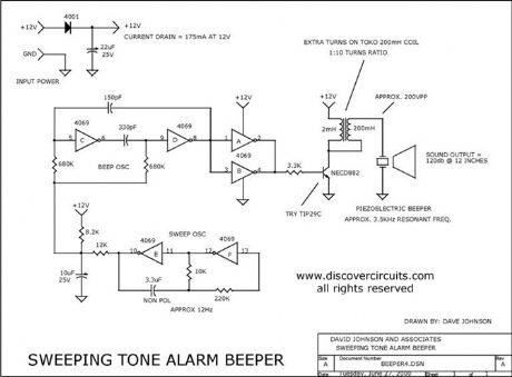
This is yet another beeper circuit that really draws attention. It sweeps the drive frequency slightly to produce a very annoying sound. It uses a transformer to increase the drive voltage across the piezoelectric device to more than 200 volts peak to peak. It cranks out an ear splitting 120db when measured at 12 inches.
Source: discovercircuits (View)
View full Circuit Diagram | Comments | Reading(2363)
Single-switch multi-light control circuit (1)
Published:2012/8/30 21:59:00 Author:Ecco | Keyword: Single-switch, multi-light, control
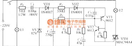
As shown in the figure, it only uses a light switch to control two groups of bulbs E1 and E2. Firstly, S is closed, E1 is lit, E2 is not lit; after S disconnects, the lamp is turned off; if S is closed again in short time (about 0.5~3s), E1 and E2 will be lit at the same time; if S disconnecting time is longer, S is closed again, that is equivalent to first closing of S.
(View)
View full Circuit Diagram | Comments | Reading(1019)
LM378 24 V DC Proportional Motor Speed Control
Published:2012/9/3 3:14:00 Author:Ecco | Keyword: 24 V DC , Proportional, Motor , Speed Control
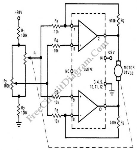
National LM378 amplifier is used as a basis for economical proportional motor speed controller. This integrated circuit is able to deliver 700 mA continuous current for such DC motor applications such as antenna rotors or motor controlled valves. The basic of proportional control is as simple as amplifying the error signal to produce an action in such direction that minimize the error. This error signal is generated by a mechanically coupled potentiometer wired in a Wheatstone bridge R1-R2-P1-P2 configuration. The potentiometer P1 is coupled to the motor shaft to sense the actual speed of the motor, act as continuous feedback sensor. (Source: freecircuitdiagram)
(View)
View full Circuit Diagram | Comments | Reading(2931)
555 IC Hysteresis for Dark Activated Relay
Published:2012/9/3 3:06:00 Author:Ecco | Keyword: 555 IC , Hysteresis , Dark Activated Relay
In the relay’s point of view, dark activated means the relay will be activated when the light intensity fall below a certain threshold. Without hysteresis, the relay will be activated and deactivated if the sensed brightness fall under or rise above a single point of darkness level. With hysteresis, the darkness level for activating and deactivating the relay will be different, and this solve the relay oscillation problem when the light intensity is swinging up and down around a single point of no hysteresis activation level.
We can employ the hysteresis of a 555 IC to improve the sensing of a drop in light, since the internal 555 circuit has 1/3 and 2/3 supply voltage thresholds. We have to use a LDR or CDS cell with aout 2 to 8 k resistance at desired light level. At the dark, the resistance of the LDR will rise and activate the relay if the voltage at pin 2 reach 2/3 of supply voltage (8V). After the relay is activated, more light is needed to make the LDR decrease its resistance until the voltage at pin 2 falls below 1/3 supply voltage (4V). (Source: freecircuitdiagram)
(View)
View full Circuit Diagram | Comments | Reading(2804)
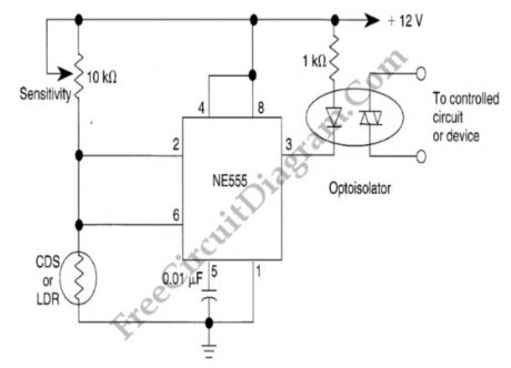
General Purpose Alarm Circuit for Resistive Sensor
Published:2012/9/3 3:01:00 Author:Ecco | Keyword: General Purpose, Alarm Circuit , Resistive Sensor
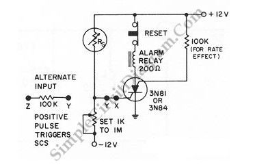

When the resistance value of a temperature, light, pressure, or any other resistive sensors Rs drops below a certain point (adjusted by a preset potentiometer), the SCR (silicon controlled switch) will be triggered. The sensor (Rs) and the potentiometer placement can be interchanged to get opposite action, where the SCR need to be triggered at the increase of sensing resistor (Rs). Here is the schematic diagram of the circuit: (Source: freecircuitdiagram)
(View)
View full Circuit Diagram | Comments | Reading(993)
Touch Switch Monostable/Timer with 555 IC
Published:2012/9/3 2:45:00 Author:Ecco | Keyword: Touch Switch , Monostable, Timer , 555 IC
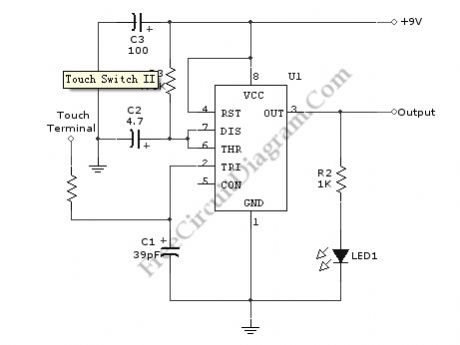
Using the given values as shown in the schematic diagram, this circuit has timed ON period of 4 seconds. The value of C2 and R3 determines the ON time, increasing the value of C2 or R3 will increase the ON time. The ON time is decreased if the value of C2 or R3 is decreased.
A schematic diagram of a touch switch circuit is shown below. This circuit consist of timer, one shoot multivibrator and touch terminal. As timer, this circuit uses 555 timer which is connected to one-shot multivibrator. The touch terminal is used to trigger this circuit. The output of this circuit can be used to drive a power transistor, CMOS circuitry, hexFET transistor or optocoupler. Here is the schematic diagram of the touch switch circuit: (Source: freecircuitdiagram)
(View)
View full Circuit Diagram | Comments | Reading(2726)
Logic Power Control for 78xx Regulator
Published:2012/9/3 2:43:00 Author:Ecco | Keyword: Logic , Power Control , Regulator
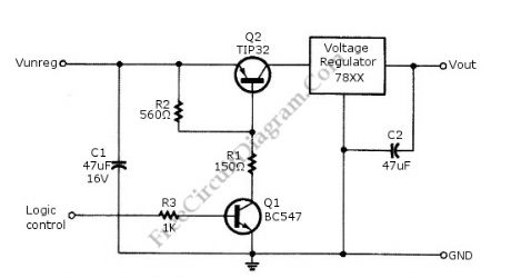
Logic power control of analog regulator can be useful in application where a digital circuit/controller need to control power source, such as in EEPROM programmer or other power controls. This is a circuit provide ON-OFF control for 78xx regulator using digital (TTL or CMOS) signal level. This circuit uses transistors in series with the 78XX regulator, which it’s base is controlled by logic level input. Here is the schematic diagram of the circuit: (Source: freecircuitdiagram)
(View)
View full Circuit Diagram | Comments | Reading(1)
Sound-Controlled Relay
Published:2012/9/3 2:38:00 Author:Ecco | Keyword: Sound-Controlled, Relay

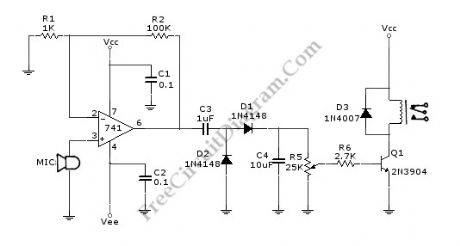
This is a relay circuit that detect the presence of sound to activate the relay. You can use this sound-controlled relay as voice operated switch, light control, toys, or any other application that can be controlled by a switch. Just replace the switch with this relay and now you have a sound-controlled device. This circuit uses a 741 operational amplifier to amplify the signal form microphone with the gain about 100 times. This circuit must use a dynamic circuit, or an electret microphone which has a battery inside. A condenser microphone can’t be used since this circuit has no biasing circuitry.
After the signal from microphone is amplified, a rectifier-doubler circuit built with D1 and D2 convert the AC signal to DC. After rectified, the AC ripple is filtered by C4 capacitor to smooth the signal. Finally, a potentiometer R5 is used to adjust the sensitivity of this circuit, calibrating the point of how loud the sound would turn on the relay.
Here is the schematic diagram of the circuit: (Source: freecircuitdiagram)
(View)
View full Circuit Diagram | Comments | Reading(1446)
Telephone Circuit: Music On Hold
Published:2012/9/3 2:16:00 Author:Ecco | Keyword: Telephone, Music On Hold
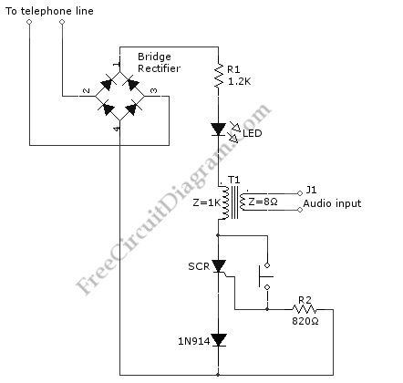
Waiting a call hold can be boring if there is only silence on the line. It’s a good thing to present an “easy music” in call hold, make a long waiting time feels much shorter. This simple circuit (consists of diodes, SCR, and some passive components) allows to place the caller on hold in one room then answer the phone again at another place, or at same phone at later time after doing something. This circuit is called music hold on circuit. This circuit will be turned off automatically when the phone is picked up the second time and the conversation can be continued. Here is the schematic diagram of the circuit: (Source: freecircuitdiagram)
(View)
View full Circuit Diagram | Comments | Reading(3073)
The speed control circuit of electric contact pressure gauge and inverter
Published:2012/8/28 21:38:00 Author:Ecco | Keyword: speed control , electric contact, pressure gauge, inverter
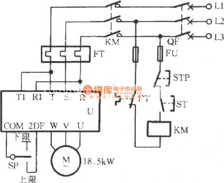
As shown in the figure, the circuit uses electric contact pressure gauge and inverter ( Japan Sanken 22kVA) to control the speed of on pump and realize water supply with constant pressure. The power supply terminal R , S , T of U can connect with switch, AC contactor. SP is installed in main road which is near the pump outlet with little effect from the amount of water.
(View)
View full Circuit Diagram | Comments | Reading(2464)
LCD backlight brightness automatically control circuit ( visible brightness sensor LX1970 )
Published:2012/8/26 22:21:00 Author:Ecco | Keyword: LCD backlight , brightness, automatically control, visible , brightness sensor
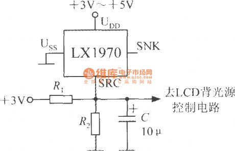
When the ambient brightness is significantly dimmed, LX1970 can automatically open the LCD backlight to make white LED emit light. Automatic brightness control circuit is shown as the chart. The resistors R1 and R2 can be used to set the minimum and maximum values of controlling brightness. Changing the capacity of the capacitor C can adjust the response time and filter out the 50Hz mains interference. LX1970 uses +3.3 ~ +5 V power supply. If the circuit only uses SRC end, SNK end should be left vacant. Assuming driving white LEDs requires output voltage of 0.25 to 1.25V, 0.25V represents the minimum brightness of the LED, 1.25V represents the maximum brightness.
(View)
View full Circuit Diagram | Comments | Reading(1274)
Smoke alarm circuit composed of photoelectric smoke detection IC MC145010
Published:2012/8/26 22:48:00 Author:Ecco | Keyword: Smoke alarm , photoelectric, smoke detection IC

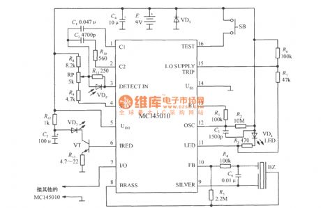
It uses 9V laminated battery. R2, C3 are respectively Oscillation resistor and oscillation capacitor, and the clock cycle is decided by following formula:
(View)
View full Circuit Diagram | Comments | Reading(1852)
Logic control prohibit circuit composed of broadband transconductance op amp and buffer OPA660
Published:2012/8/22 22:11:00 Author:Ecco | Keyword: Logic control , prohibit circuit , broadband transconductance, op amp, buffer
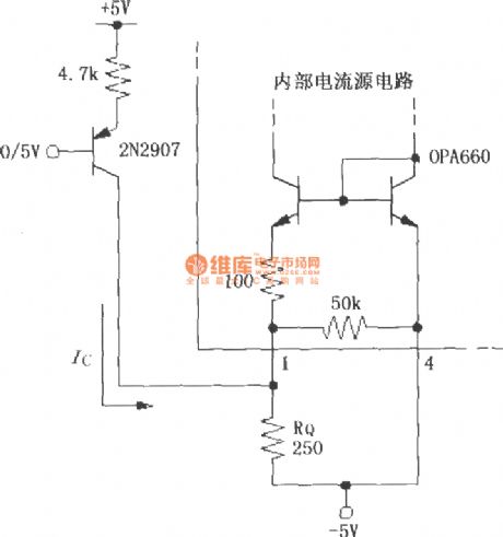
The circuit adds a transistor 2N2907 to control pin 1 of OPA660 1. When the 2N2907 base is extremely 0V, transistor gets conduction, Ic = 1mA, RQ voltage rises to 1V which is higher than the negative power supply (-5V), OPA660's static current is reduced to 0, OPA660 is prohibited from working; Conversely, when the base is extremely 5V, the transistor is cut, Ic = 0mA, RQ voltage drops to make OPA660 quiescent current increase, OPA660 is allowed to work.
(View)
View full Circuit Diagram | Comments | Reading(1083)
The circuit of photoelectric controlling
Published:2012/8/21 3:38:00 Author:Ecco | Keyword: Photoelectric controlling
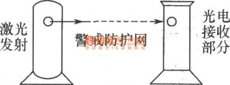
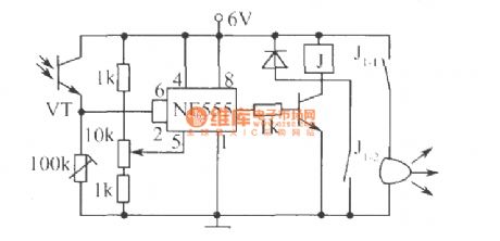
Photoelectric control circuit is shown as the figure. NE555 circuit is the core component of the circuit, when photodiode VT receives laser irradiation and turned on, the pin 6 threshold of time-base circuit and pin 2 of trigger end rise above 4V, so the pin 3 outputs low, relay does not pull. When the laser is blocked, VT is turned off, pin 2 and pin 6 become low, pin 3 outputs high, relay is energized, J1-2 pulls to get self-locking, J1-1 pulls to make bells issue alarm sound. The installation can be made according to the following figure, the transceiver end needs to be made as removable or fixed Alert Network. if someone blocks laser path, the alarm emits sound. It can be widely used in warehouse, station temporary heap objects, large area of orchards and other protection applications.
(View)
View full Circuit Diagram | Comments | Reading(991)
New punch program controller circuit
Published:2012/8/20 0:52:00 Author:Ecco | Keyword: New punch , program controller
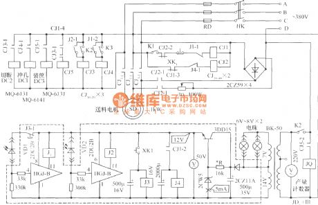
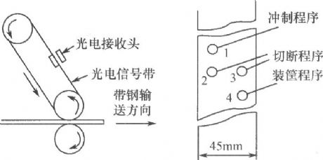
The device is develped in the process of transformation of the old-fashioned punch. It is suitable for punching and cutting the ribbon steel - based products, and it has the advantages of simple, reliable, anti-interference, automatically processed products with the optical signal. The device's circuit is shown below. The listening and reading structure with Optical signal is composed of two 6V ~ 8V bulbs (without condenser ) and two photodiodes and its attachments. Its schematic diagram is shown below. Optical signal is generated by a stick of 1.5mm thick black tape. Information location of each program is shown below.
(View)
View full Circuit Diagram | Comments | Reading(698)
| Pages:63/312 At 206162636465666768697071727374757677787980Under 20 |
Circuit Categories
power supply circuit
Amplifier Circuit
Basic Circuit
LED and Light Circuit
Sensor Circuit
Signal Processing
Electrical Equipment Circuit
Control Circuit
Remote Control Circuit
A/D-D/A Converter Circuit
Audio Circuit
Measuring and Test Circuit
Communication Circuit
Computer-Related Circuit
555 Circuit
Automotive Circuit
Repairing Circuit