
Control Circuit
Index 78
Circulatory timing flashlight circuit diagram
Published:2011/9/6 21:09:00 Author:Vicky | Keyword: circulatory timing flashlight
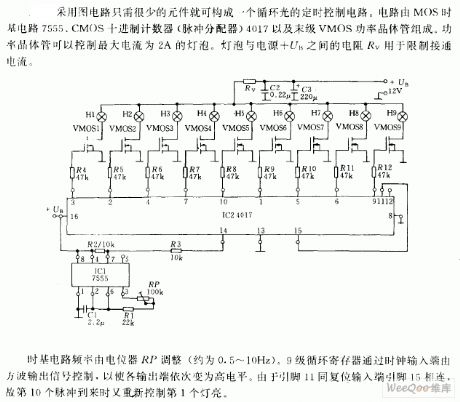
In accordance with the picture, the circulatory timing control circuit can be composed of very few components. The circuit is composed of MOS time base circuit 7555, CMOS decimal counter (pulse distributor) 4017 and last-stage VMOS power transistor. Power transistor can control lamp bulb of current up to 2A. The resistance Rave between the lamp bulb and power +UB is used to control the current.
The time base circuit frequency is modulated by potentiometer RP (about 0.5 ~ 10Hz), and the nine-stage circulatory register is controlled by the square wave output signal via clock input end, so as to make every output ends turn to high level in turn. Because the pin11 reset input end is connected with pin 15, the first lamp gives out light when the 10th pulse comes.
(View)
View full Circuit Diagram | Comments | Reading(1363)
The photo control electric switch
Published:2011/9/5 22:50:00 Author:Seven | Keyword: photo control, electric switch
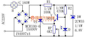
Working principles: see as the figure, after the 220V AC passes the bulb H and the rectifier bridge, it becomes the DC pulse voltage as the forward biased voltage, which can be added on the SCR VS and branch R. In daylight, when the brightness is over some degree, the LDR D is in a low resistance which is ≤1KΩ, so the triode V is blocked and there is no current out from it, the single way SCR VS is blocked due to the lack of trigger current. At the moment, the current past bulb H is ≤2.2mA, the bulb is not glowing. (View)
View full Circuit Diagram | Comments | Reading(1130)
Electromotor indicator light circuit controlled by five switches
Published:2011/9/1 2:49:00 Author:Christina | Keyword: Electromotor, indicator light, five switches
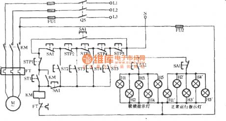
From the point of view of electrical safety, the necessary contact is indispensable when we are installating and debugging, repairing or processing. As the figure shows, the H1-H5 are the contact instruction signals, the H1 ~H5 are the normal operation instructions. When you are debugging, repairing or processing the equipment, the interlocking button SA1 is in the position of interlocking position , the three pairs of normally closed contact points cut off, the two pairs of normally open contact points close, the AC contactor KM controls the on/off of the KM through the equipment main control buttons ST1, STP1 only.
(View)
View full Circuit Diagram | Comments | Reading(1246)
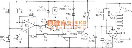
Lower limit temperature frog sound alarm and automatic heating control circuit
Published:2011/9/1 2:54:00 Author:Christina | Keyword: Lower limit, temperature, frog sound, alarm, automatic heating, control circuit
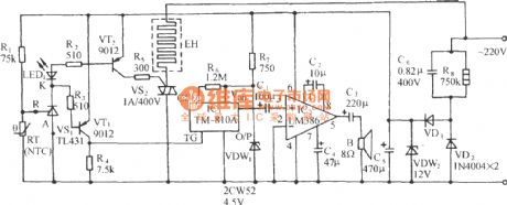
As the figure shows, it is composed of the lower temperature detection circuit, the alarm circuit, the heating circuit and the AC step-down rectifier circuit.
(View)
View full Circuit Diagram | Comments | Reading(881)
Lower limit temperature bird sound alarm and automatic heating control circuit
Published:2011/9/1 2:54:00 Author:Christina | Keyword: Lower limit, temperature, bird sound, alarm, automatic heating, control circuit
View full Circuit Diagram | Comments | Reading(1073)
EDM control circuit
Published:2011/9/1 2:51:00 Author:Christina | Keyword: EDM, control circuit
View full Circuit Diagram | Comments | Reading(4345)
Small breaker direct start-up circuit
Published:2011/9/1 3:15:00 Author:Christina | Keyword: Small breaker, direct start-up

The small breaker has a lot of models such as the CN45, the rated current is 63A, there are dozens kinds of buckle-off current which are from 3A to 63A. According to the rated current and the operating specification of the small electromotor, we can use the small breaker with appropriate buckle-off current as the operation switch of the electromotor, it is easy to operates and can protect the electromotor. As the figure shows, the FU is fuse protector, it has the function of short circuit protection and it can cut off the power when you are repairing the fuse QF.
(View)
View full Circuit Diagram | Comments | Reading(834)
Smoke detection alarm circuit
Published:2011/9/1 3:47:00 Author:Christina | Keyword: Smoke, detection, alarm circuit
View full Circuit Diagram | Comments | Reading(891)
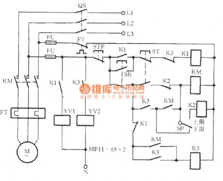
Automatic reversing circuit of the phase-electromotor with the inching switch
Published:2011/9/2 2:28:00 Author:Christina | Keyword: Automatic reversing circuit, phase-electromotor, inching switch
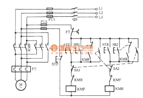
As the figure shows, the SA1 and SA2 are the position limit switches; the SB1 and SB2 are the inching switch. Set the SB1 as an example, it is a composite switch, you can start the KMF by pressing it, the electromotor operates positively, if you unclasp the finger, the KMF will loss power, so the electromotor is in the inching state. After you press the STF, the normally closed contact point of SB1 is in the closed state, so the KMF can protect itself, the electromotor can operate long-standing. Set the SA1 as an example, in the normal operation condition, after the mechanical hits the inching switch SA1, the normally closed contact point cuts off to cut off the KMF return circuit, the electromotor stops.
(View)
View full Circuit Diagram | Comments | Reading(1972)
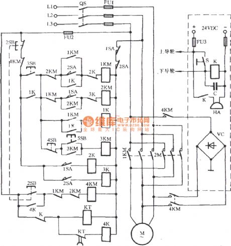
Remote control electronic control lock alarm TH151A/B, the micro vibration sensor T968
Published:2011/9/2 2:34:00 Author:Christina | Keyword: Remote control, electronic control, lock alarm, micro vibration sensor
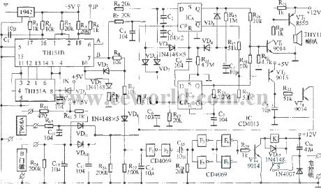
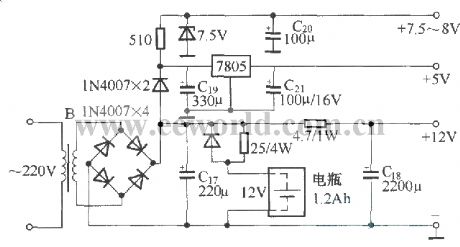
This circuit is composed of the anti-theft host computer, the door magnetic sensor trigger switch, the micro vibration sensor switch, the electric control lock with the key, the free maintenance battery and the AC power supply. The host computer circuit:
(View)
View full Circuit Diagram | Comments | Reading(1067)
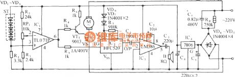
The speaker overload protection circuit
Published:2011/9/1 3:47:00 Author:Christina | Keyword: speaker, overload, protection circuit
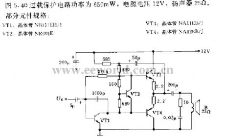
The speaker overload protection circuit is as shown in figure 5. The power is 650mW, the power voltage is 12V, the resistance of the speaker is 25Ω.
(View)
View full Circuit Diagram | Comments | Reading(2720)
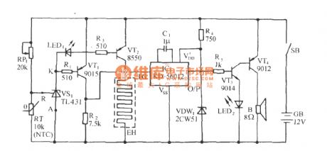
Sprout greenhouse constant temperature control and cricket sound alarm circuit
Published:2011/9/2 2:55:00 Author:Christina | Keyword: Sprout, greenhouse, constant temperature, control, cricket sound, alarm circuit
As the figure shows. It is composed of the temperature detection circuit, the relay control heating circuit, the cricket sound alarm circuit and the AC step-down rectifier circuit. It can control the temperature of the 10~16m2 greenhouse in the range of 28℃±0.5℃. When the temperature is lower than the set temperature, the circuit will connect to the electric heater automatically and send out the sound of cricket to alarm the host.
(View)
View full Circuit Diagram | Comments | Reading(1283)
Gas stove flameout sound and light alarm circuit
Published:2011/9/2 3:02:00 Author:Christina | Keyword: Gas stove, flameout, sound, light, alarm circuit
In the process of using, the stove fire always extinguished by the wind or water, it is very dangerous when there is no people. This gas stove flameout sound and light alarm circuit can send out the sound and light alarm signal when the fire is extinguished to remind the user. The circuit is as shown in the figure.
(View)
View full Circuit Diagram | Comments | Reading(1022)
The hydraulic pressure control circuit
Published:2011/9/1 3:48:00 Author:Christina | Keyword: hydraulic, pressure, control circuit
View full Circuit Diagram | Comments | Reading(1053)
Fence disconnection voice alarm circuit
Published:2011/9/4 21:31:00 Author:TaoXi | Keyword: Fence, disconnection, voice alarm circuit
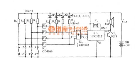
As the figure shows, it is composed of the fence cordon, the disconnection LED indicating circuit, the 4-channel NOR gate and voice circuit. When one side of the fence is damaged, the LED can indicate which side is damaged, at the same time, the circuit sends out the voice of Dudu, Please mind to alarm the host.
(View)
View full Circuit Diagram | Comments | Reading(1358)
Microcomputer hand washing and water filling dual-purpose controller
Published:2011/9/4 22:04:00 Author:TaoXi | Keyword: Microcomputer, hand washing, water filling, dual-purpose, controller
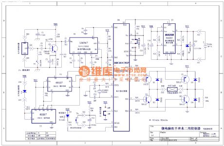
View full Circuit Diagram | Comments | Reading(934)
Four diodes rectifier energy consumption braking circuit
Published:2011/9/4 22:12:00 Author:TaoXi | Keyword: Four diodes, rectifier, energy consumption, braking circuit

View full Circuit Diagram | Comments | Reading(1028)
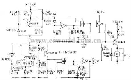
Example of the speed control circuit
Published:2011/9/4 22:16:00 Author:TaoXi | Keyword: Example, speed control
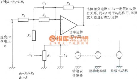
Proportional-derivative circuit: C has no relationship with the certain value of Vc, R3C has the function to Vf. The operational amplifier finishes the differential operation.
(View)
View full Circuit Diagram | Comments | Reading(904)
The emergency circuit of the AC contactor with the damaged auxiliary contact
Published:2011/9/4 22:27:00 Author:TaoXi | Keyword: emergency circuit, AC contactor , damaged auxiliary contact

View full Circuit Diagram | Comments | Reading(1404)
Special cultivation temperature control and wave-sound circuit
Published:2011/9/4 22:32:00 Author:TaoXi | Keyword: Special cultivation, temperature control, wave-sound circuit
As the figure shows, it is composed of the temperature sensing devices, the comparison circuit, the silicon controlled temperature control circuit, the wave- sound circuit and the AC step-down rectifier circuit. This circuit is simple, practical and it has the wide temperature range and high control precision.
(View)
View full Circuit Diagram | Comments | Reading(745)
| Pages:78/312 At 206162636465666768697071727374757677787980Under 20 |
Circuit Categories
power supply circuit
Amplifier Circuit
Basic Circuit
LED and Light Circuit
Sensor Circuit
Signal Processing
Electrical Equipment Circuit
Control Circuit
Remote Control Circuit
A/D-D/A Converter Circuit
Audio Circuit
Measuring and Test Circuit
Communication Circuit
Computer-Related Circuit
555 Circuit
Automotive Circuit
Repairing Circuit