
Control Circuit
Index 75
TX05C-R infrared surveillance alarm circuit
Published:2011/9/12 22:03:00 Author:John | Keyword: infrared surveillance alarm
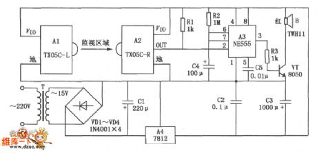
TX05C-R infrared surveillance alarm circuit is shown. It can be used for surveillance of walls, windows, doors and various restricted areas. If someone breaks into or over the alarm position, it will sound to play a security role. The circuit consists of transmitter module, receiver module, time-base circuit, power circuit, the speaker and other parts. And the power supply circuit is formed by the transformer T, rectifier diodes, three-terminal voltage regulator integrated circuit A4 and other parts. It can output 12V DC voltage to power the entire circuit. (View)
View full Circuit Diagram | Comments | Reading(1929)
A Darlington Servo Circuit Diagram Driven by Operational Amplifier
Published:2011/9/12 23:49:00 Author:Zoey | Keyword: Darlington, Servo Circuit Diagram , Operational Amplifier
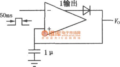
Following picture shows how operational amplifier drives the Darlington Servo circuit. This circuit carries and sets two power and voltage pins of 741, and then offers the two Darlington pipes margin input signals. From the statistic in the picture, we can see that the circuit can provide 30W’s power for 8Ωload. The input signal frequency can be as large as 100kHz. Circuit plus is 10 and circuit distortion is less than 0.2%.
(View)
View full Circuit Diagram | Comments | Reading(758)
Circuit diagram of controlling groups of light by one single switch
Published:2011/9/7 1:25:00 Author:Vicky | Keyword: controlling, lingt, single switch
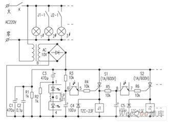
As shown in the above circuit diagram, when the power switch K is conducted for the first time, 1# light illumines at once. Because voltage of the capacitor C3 would not change suddenly, the photo-coupler G is conducted only at the moment that switch K is conducted. But soon G stops. In addition, saltation does not occur to the voltage of the capacitance C4, so silicon controlled rectifier S1 would not be conducted (C1 hasn’t generated voltage at the moment of the connection of K, likewise, S2 would not be conducted). Therefore, 2# and 3# light would not lighten. (View)
View full Circuit Diagram | Comments | Reading(1286)
Light-operated Automatic Scintillating Road Signal Lamp Circuit Composed of 555
Published:2011/8/25 7:48:00 Author:Sue | Keyword: Light-operated, Automatic Scintillating, Road Signal Lamp
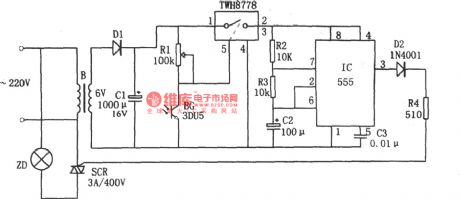
The picture shows the light-operated scintillating road signal lamp circuit. The circuit consists of voltage reduction and rectification circuit, light-operated switch, 555 multivibrator, among which the voltage reduction and rectification circuit provides the whole circuit with direct current voltage.
In the circuit, BG is 3DU-type photosensitive triode. In the daytime, when there is light, BG's terminal voltage is small(1.6v) which will make power tube TWH8778 disconnected because of pin 5's low level. Then multivibrator doesn't work correspondingly and silicon controlled rectifier SCR is not connected. The lamp ZD is not illuminated. When it is dark, the photosensitive tube's inner resistance value becomes higher and even broken. TWH8778 is connected because of pin 5's high level(1.6V) which will make 555 oscillator begin to work because of the connection of the power circuit. (View)
View full Circuit Diagram | Comments | Reading(1196)
Lamp Circuit for Directional Signals of Automobiles Composed of 555
Published:2011/8/25 7:47:00 Author:Sue | Keyword: Lamp Circuit, Directional Signals, Automobiles
View full Circuit Diagram | Comments | Reading(749)
Nighttime Automatic Illumination Circuit Composed of μA555
Published:2011/9/8 1:48:00 Author:Sue | Keyword: Nighttime, Automatic, Illumination
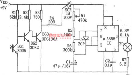
BG1(3DU5) in the photoelectric switch is photosensitive triode which has different resistance value under different light. In the daytime, it has a low resistance value because of the light which will make BG2 disconnected and BG3 will be connected. The silicon controlled rectifier SCR is disconnected and the oscillator doesn't work because of lack of electricity, and the pilot light is not illuminated. In the nighttime, BG1 will have high resistance value between c and e, which will make BG2 connected and BG3 will be disconnected. SCR is connected and the corresponding oscillator begins to work because the power circuit is connected. Its output signal will drive the pilot lamp ZD to illuminate which will draw people's attention. By adjusting W1, striking flash light interval can be achieved. (View)
View full Circuit Diagram | Comments | Reading(1382)
The Circuit Diagram of the 0.1~10Hz Filter (OP07)
Published:2011/8/12 4:51:00 Author:Felicity | Keyword: 0.1~10Hz Filter
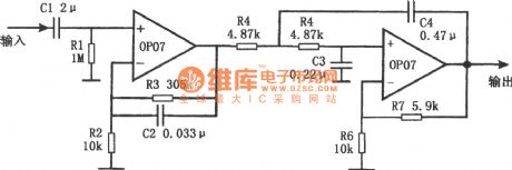
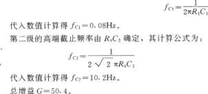
The figure shows the circuit diagram of the 0.1~10Hz filter. It’s composed of two parts. Part one is high-pass filter and part two is low-pass filter. The signal the frequency of which is above 0.1Hz can pass the first part and the signal the frequency of which is above 10Hz will be filtered out by the second part. And then the band-pass filtration is complete. The first part is non-inverting amplifier and the cutoff frequency depends on R1C1, as showed in the formula below: (View)
View full Circuit Diagram | Comments | Reading(2491)
10MHz Band-Pass Filter Composed of OPA603
Published:2011/9/11 20:29:00 Author:Felicity | Keyword: 10MHz, Band-Pass, Filter
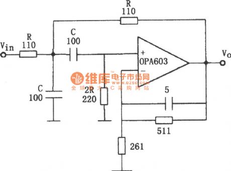
The circuit makes use of the Broadband Features high-speed current feedback op amp (G=1~10, the broadband reaches 100MHz). It makes the 10MHz pass filter. The parameter is showed in picture. (View)
View full Circuit Diagram | Comments | Reading(1412)
12 bit D/A Commutator with Parallel Ports
Published:2011/9/4 7:32:00 Author:Joyce | Keyword: 12 bit, D/A , Commutator , Parallel Ports
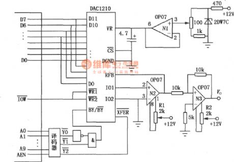
DAC1210 is compatible with end I/O of the bus line of PCXT. Its reference voltage is provided by external circuit with 12 bit data parallel transmission. It has the structure of pair register. Due to parallel connection, the data conversion speed is fast (≤1μs) .Similar models are DAC1208, DAC1209, MP1209, MP1210, which are commonly used in industrial automation control and automatic measurement circuits. As shown in the figure is its typical application circuit. (View)
View full Circuit Diagram | Comments | Reading(1151)
Language filter circuit
Published:2011/9/9 1:56:00 Author:John | Keyword: Language filter circuit
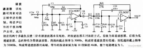
The circuit can be used to limit the language frequency band, which can remove interference and noise except the clatter. This function can be achieved by two multiple negative feedback with two second-order active filters. Two filters are set in a cascaded manner, whose pre-end is the high-pass filter and pro-end is the low-pass filter. The overall characteristics appear to be that of the band-pass filter. High-pass filter’s cutoff frequency is 300Hz, which can constitute the lower end of band-pass filter; and low-pass filter’s cutoff frequency is 3000Hz, which can constitute a higher end of band-pass filter. The rolling band’s attenuation is 40 dB per 10 octave and the circuit’s gain is 1.
(View)
View full Circuit Diagram | Comments | Reading(840)
the agricultural liquid level automatic control circuit consisting of NE555
Published:2011/8/20 2:13:00 Author: | Keyword: the agricultural liquid level, automatic control
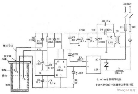
If just turns on the power ,the IC (555) ② pin is low level due to the voltage on C3 can't mutations when there isno water in the pool, 555 is set,high level outputby3-pinmakes the SSR end and the motor D is not running. At this point C3,C4 charge respectively through R1, R2, when the voltage on C4 charges to 2/3VDD, IC is reset,low level output by 3-pin makes SSR internal photoelectric coupler connect the AC voltage 220V, motor D has electricity and runs to pump water. When the water level rises to b probe, C4 is discharged through the water, but 555 still outputs low level,the motor D continues to run.
(View)
View full Circuit Diagram | Comments | Reading(3721)
High-speed complementary output voltage comparator circuit
Published:2011/8/20 2:10:00 Author: | Keyword: High-speed, complementary output, voltage comparator
LM161/261/361 transmission speed is high,it has the general power supply voltage and independent strobe terminal, it can output two complementary TTL signal that delays small and theinput disorder voltage is small,when driving over,the switching speed is small and it uses dual in-line type.The high-speed peak detector is shown as above.
(View)
View full Circuit Diagram | Comments | Reading(895)
Double contact-plate resistance bridge touch switch circuit diagram
Published:2011/9/9 8:00:00 Author:Vicky | Keyword: double contact-plate, resistance bridge touch switch
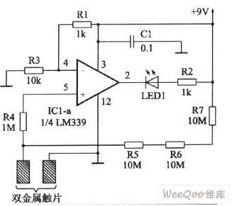

Resistance bridge touch switch in the picture 1 is composed of LM339. LM339 is a a quad voltage comparator (with 4 identical voltage comparator inside). The circuit only takes use of one of the four. Work voltage range reaches 2-32V. When hands are very close to the double metal plate but not touch them, pin2 of LM339 outputs low level signal, which makes the luminous diode LED1 conducted and lightened.
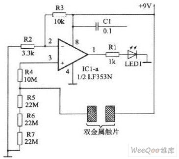
The difference of the resistance bridge touch switch in the picture 2 from picture 1 lies in that it adopts calculating amplifier LF353N instead of voltage comparator. (View)
View full Circuit Diagram | Comments | Reading(2302)
Reversible Running Illumination Controller(C043,C301,C188,C003)
Published:2011/8/25 7:43:00 Author:Sue | Keyword: Reversible, Running Illumination, Controller
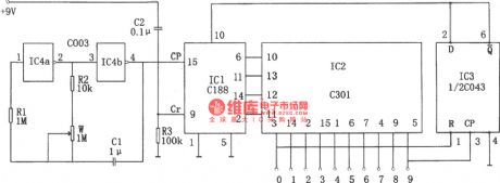
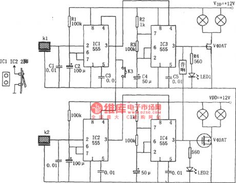
When IC2'spin 9 outputs high level, this level signal will be put on IC3's CP terminal and will make it reverse. IC1's U/D terminal will become high level.Then IC1 will begin to count by subtraction from next clock pulse which will make the controlled illumination be turned on by turns from 9 - 0 . When IC2's 0 terminal outputs high level, the above-mentioned process will be repeated which will make IC1 begin to count by addition. So the repetition of the above-mentioned process can realise the reversible control of the running illuminations.
Besides, by adjusting potentiometer w in the circuit, the running speed can be adjusted.What's more, ifresistance value of resistor R2 is increased properly, the running speed of the illuminations can be lower than 0.5HZ. (View)
View full Circuit Diagram | Comments | Reading(750)
Advertising Decor Lamp Controller Composed of 555
Published:2011/8/25 7:47:00 Author:Sue | Keyword: Advertising Decor Lamp, Controller
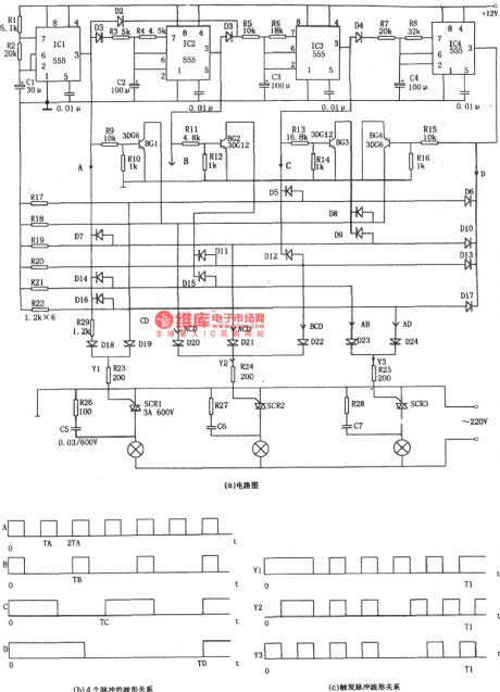
IC1 and R1,R2,C1 constitute multivibrator and its oscillating frequency f=1.44/(R1+2R2). The corresponding parameter in the circuit is about 4Hz. As seen in the figure (b), we can see from B that IC2 and R3,R4,C2 constitute trigger circuit which will realise two frequency division of IC1's output square wave A. As seen in the figure (b), we can see from C that IC3 and R5,R6,C3 constitute trigger circuit which will realise three frequency division of IC1's output square wave A. As seen in the figure (b), we can see from D that IC4 and R7,R8,C4 constitute trigger circuit which will realise six frequency division of IC1's output square wave A. (View)
View full Circuit Diagram | Comments | Reading(714)
The remote controller of drainage and irrigation pumping station
Published:2011/9/6 4:43:00 Author:Felicity | Keyword: remote controller, drainage and irrigation pumping station
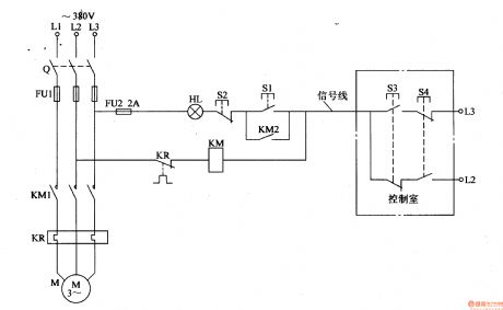
On remote start, press S3, and the phase voltage of L3 goes through the normally open contact of S3 to put on KM, And KM turns on, and the normally open contact KM1, KM2 closes and the pump motor starts. After release S3, the phase voltage of L3 goes through FU2, HL, S2, normally open contact KM2, KM and the normally close contact of KR to phase L2 to make up circuit and maintaining KM close.When it needs to stop, press S4 to make KM off and the pump motor M stops.
(View)
View full Circuit Diagram | Comments | Reading(941)
Colourful Lights Controller Twenty-nine
Published:2011/8/12 4:50:00 Author:Felicity | Keyword: Colourful Lights Controller
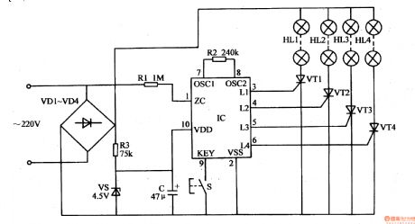
This colourful lights controller contains SH804 or SH805 colourful lights oriented controller IC.SH-804,SH-805 are the same with SH803 in shape,inner circuit and application circuit, while the stored control program and the function of pins are different. SH-804 has 10 lights repetition modes and 6 change speeds.The modes can cycle automatically or be set by control buttons. SH-805 has 16 repetition modes which can be set by control buttons. The application circuits of SH-804 and SH-805 are shown in Fig.1-144 and Fig.1-145,the select of components of which can refer to the application part of SH-803. (View)
View full Circuit Diagram | Comments | Reading(995)
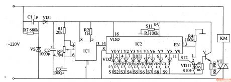
Timing Controller (the 2nd)
Published:2011/8/12 4:53:00 Author:Felicity | Keyword: Timing Controller
Work of the circuit
The circuit consists of Power supply circuit, pulse generator, control implementation delay circuit and control circuit. ( It is showed in picture 8-91.)
Power supply circuit consists of buck capacitor Cl, discharge resistor R7, voltage regulator diode VS, the rectifier diode VDl and filter capacitor C2.
Pulse generator consists of time-base integrated circuit ICl, resistors Rl and R2, potentiometers RP and capacitors C3.
Control implementation delay circuit consists of decimal counting / pulse distributor circuit IC2, resistors R3 and R4, diode VD2-VD11, switch S1-S12.
Control circuit consists of transistor V, resistors R5 and R6, thyristor VT and AC contactor KM. (View)
View full Circuit Diagram | Comments | Reading(1040)
Liquid Level Controller (the 2nd)
Published:2011/8/12 4:52:00 Author:Felicity | Keyword: Liquid Level Controller
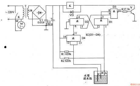
Work of the circuit
The circuit consists of power circuit and level detection and control circuit. (It is showed in picture 8-100.)
The power circuit consists of power transformer T, bridge rectifier UR and filter capacitor Cl, C2.
Level detection and control circuit consists of level electrode AC, four NAND gate IC IC (Dl-D4), the transistor V, resistors Rl-R3, relay K and diode VD.
220V AC voltage is bucked by T ,rectified by UR and filtered by C1, C2. It then supplies 12V voltage to relay K and IC. (View)
View full Circuit Diagram | Comments | Reading(1405)
The circuit diagram of the high gain band-pass filter (LM307) with low Q
Published:2011/8/12 4:54:00 Author:Felicity | Keyword: high gain, band-pass filter
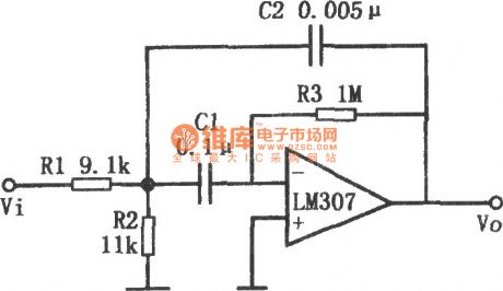
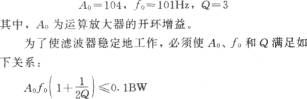
The circuit of the high gain band-pass filter with low Q is shown in this figure. Adding multiple feedback circuit to operational amplifier can build up a high gain band-pass active filter with low Q. This circuit adopts LM307 operational amplifier, using the components’ parameters in this figure to calculate: BW is the bandwidth when the gain of the operational amplifier is 1.
(View)
View full Circuit Diagram | Comments | Reading(1426)
| Pages:75/312 At 206162636465666768697071727374757677787980Under 20 |
Circuit Categories
power supply circuit
Amplifier Circuit
Basic Circuit
LED and Light Circuit
Sensor Circuit
Signal Processing
Electrical Equipment Circuit
Control Circuit
Remote Control Circuit
A/D-D/A Converter Circuit
Audio Circuit
Measuring and Test Circuit
Communication Circuit
Computer-Related Circuit
555 Circuit
Automotive Circuit
Repairing Circuit