
Control Circuit
Index 62
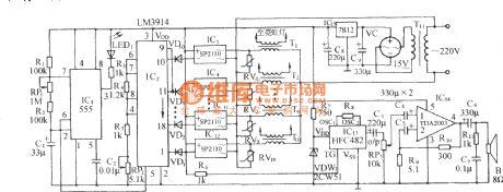
Voice-control bi-directional flowing water color lantern with sea wave circuit
Published:2012/9/10 1:22:00 Author:Ecco | Keyword: Voice-control, bi-directional , flowing water, color lantern , sea wave
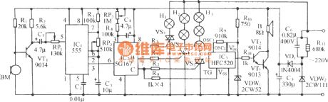
As shown in the diagram, the circuit consists of voice control circuit, monostable trigger, ring count pulse distribution circuit/drive circuit, thyristor trigger control circuit, sea wave sound audible circuit and AC buck rectifier circuit, it can make three-way Lantern strings auto reverse in both directions, accompanied by the nature sound from mountain and stone or waves beating the shore.
(View)
View full Circuit Diagram | Comments | Reading(1054)
The triac liquid level control circuit
Published:2012/9/9 22:09:00 Author:Ecco | Keyword: triac , liquid level control
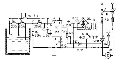
As shown in the figure, the controller is composed of the water level controller, trigger controller, and buck rectifier circuit.
The water level detecting electrodes a , b , c, and W1 , R1 , R2, and R3 form a bias circuit which can be used as a liquid level detector.
When the water surface is below b, VP -b ≈ R3 x VDD / ( RW1 + R1 + R2 + R3 ) < 1/3VDD, 555 is set, SCR is triggered and turned on, then the motor runs for pumping.
When the water level raises to a, Vp - a ≈ R3 x VDD / ( Rw1 ten R3 ) > 2/3VDD, then 555 resets, pin 3 is in low level. SCR is turned off, the motor stops because of no electricity, and then the circuit runs in the cycle to maintain the water level in a certain range.
(View)
View full Circuit Diagram | Comments | Reading(2078)
Four-color advertising light box with songs sound control circuit
Published:2012/9/9 22:47:00 Author:Ecco | Keyword: Four-color, advertising light box , songs sound control
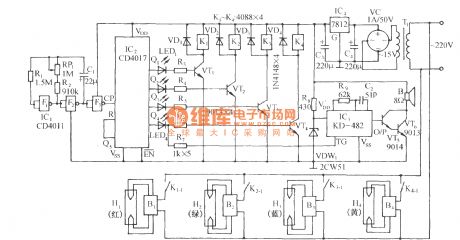
The circuit is shown as the figure. It is composed of time-base oscillator circuit, pulse count / distribution circuit, relay control circuit, songs sound circuit and AC buck rectifier circuit and other components. The circuit is used for advertisements, while it automatically transforms luminous color, it also issues a melodious music , it can not only beautify the night scene,but increaseadvertising effect . F1, F2, F3are the gate circuits ofa four- 2 NAND gate integrated circuit CD4011, where F1, F2 , and R1 , R2, and RP1, C1 form a multivibrator with oscillation frequency:
The oscillation period of the icon parameter is 44 ~ 92s, regulation RP1 can change its oscillation cycle TO.
(View)
View full Circuit Diagram | Comments | Reading(1134)
Motion Alarm Using Piezoelectric Device
Published:2012/9/9 20:40:00 Author:Ecco | Keyword: Motion Alarm, Piezoelectric Device

An inexpensive piezoelectric device is used as a motion sensing device for this motion alarm.
Source: discovercircuits (View)
View full Circuit Diagram | Comments | Reading(1290)
Medium Power 12v Brush Motor Speed Controller July 13, 2008
Published:2012/9/9 20:37:00 Author:Ecco | Keyword: Medium Power, 12v, Brush Motor, Speed Controller
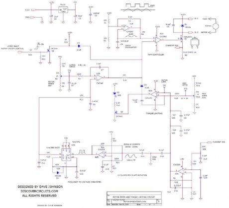
In many applications, you would like to hold the speed of a motor constant, even as variations in the power supply voltage or mechanical load try to change its speed. In other applications, the average current to the motor needs to be limited, so the initial in-rush current when starting the motor is not too high. Also in some applications you would like to allow the motor to be in locked in a stall condition, without doing harm to the motor or the drive circuit. These two features can often be combined in a single control circuit.
Source: discovercircuits (View)
View full Circuit Diagram | Comments | Reading(1078)
SOLAR POWERED PUMP MOTOR CONTROLLER
Published:2012/9/9 20:35:00 Author:Ecco | Keyword: SOLAR, POWERED , PUMP , MOTOR CONTROLLER
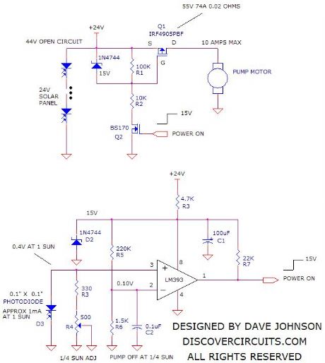
A Discover Circuits visitor had a problem. He needed a simple on/off controller for his solar powered water pump. His system used two 12v 50 watt solar panels wired in series. The power from the solar panels drove a submerged water pump. However, during overcast skies the pump motor did not operate properly due to the lack of power from the panel. He wanted a circuit which would turn off power to the motor during low sun conditions. The circuit below performs this function. A small 0.1? x 0.1? photodiode monitors the sunlight intensity. The current from the diode is proportional to sunlight intensity. An adjustable load resistor across the diode converts the current into a voltage and feeds the to a voltage comparator circuit. The output of the comparator drives a small n-channel MOSFET, which in turn drives a high current p-channel MOSFET, controlling power to the pump motor. When the sunlight is less than one fourth of full intensity, power to the motor is turned off.
Source: discovercircuits (View)
View full Circuit Diagram | Comments | Reading(2183)
CIRCUIT PROTECTS BATTERY POLARITY REVERSAL
Published:2012/9/9 20:33:00 Author:Ecco | Keyword: PROTECTS , BATTERY , POLARITY REVERSAL

This simple circuit can protect a sensitive electronic circuit from an accidental connection of a battery with a reversed polarity. The N-channel FET connects the electronic device to the battery only when the polarity is correct. The circuit shown was designed for a device powered from a single 1.5 volts button cell battery. However, the circuit will operate with higher voltages as well.
Source: discovercircuits (View)
View full Circuit Diagram | Comments | Reading(2186)
The manual series resistor to start three-phase motor circuit
Published:2012/9/6 22:32:00 Author:Ecco | Keyword: manual series resistor , start , three-phase motor
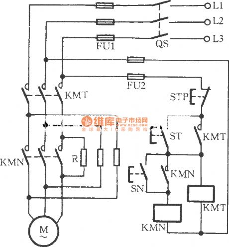
Operation method: you can click the start button ST, and AC contactor KMT will pull in, then the motor M connected to the startup resistor R in series will start. Until the motor speed is up to 70% of rated speed, and then clicking the run button SN again, KMN pulls in, and its main contact makes R be shorted connected and provides rated voltage for motor M, then the motor will enter the rated operating status.
(View)
View full Circuit Diagram | Comments | Reading(1270)
Water tower, pool water recycling control circuit
Published:2012/9/6 22:14:00 Author:Ecco | Keyword: Water tower , pool water , recycling control

Some places reqiure ( such as stone cutting ) high water consumption, in order to save water and reduce pollution, these place usually utilize water recycling meyhod. The used water flows into the pool, then it is pumped to the water tower. The water recycling control circuit shown in figure can realize water pump automatic control.
(View)
View full Circuit Diagram | Comments | Reading(1746)
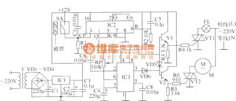
Bathroom door controlled switch circuit (3)
Published:2012/9/6 22:01:00 Author:Ecco | Keyword: Bathroom door , controlled switch
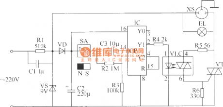
It uses magnetron door switch ( it is composed of permanent magnet and doorframe Reed mounted on the door ) to control the lights and exhaust fan in bathroom, it is easy to use, safe and reliable. The bathroom door controlled switch circuit consists of the power circuit and control circuit, and it is shown in the figure.
R1, R5 and R6 select 1/2W metal film resistors; R2~ R4 select 1/4W or 1/8W metal film resistors.C1 selects the polyester capacitor or CBB capacitor with pressure valuebeing more than 400V; C2 and C3 select 16 V aluminum electrolytic capacitors.VD uses 1N4007 type silicon rectifier diode.VS selects 1W, 9.1V silicon voltage diode .VT uses 2A, 400V TRIAC .VLC selects NOC 3020 optocoupler.IC uses CD4017 decimal counting / divider integrated circuit.SA uses the normally closed reed switch.
(View)
View full Circuit Diagram | Comments | Reading(836)
Bathroom door controlled switch circuit (1)
Published:2012/9/6 21:42:00 Author:Ecco | Keyword: Bathroom door , controlled switch
It uses magnetron six switch to control lights and exhaust fan in the bathroom, and it has strong practical applicability. The bathroom six control switch circuit is composed of the power circuit and control circuit, and it is shown in Fig.R1 ~ R6 select 1/4W carbon film resistors.RP uses small membrane potentiometer ( it is used to adjust the delay time of the exhaust fan ).C1, C2 and C4 select aluminum electrolytic capacitors with voltage in 16V; C3, C5 ~ C7 choose polyester capacitors.VD1 ~ VD6 choose 1N4007 silicon rectifier diodes.V1 and V2 select S9013 or S8050 silicon NPN transistors.VT1 and VT2 selects Triacs with current in 3A and voltage being400V or more.ICl uses LM7812 three-terminal integrated voltage regulator; IC2 uses CD4027 digital integrated circuit; IC3 uses NE555 time-base integrated circuit.T uses 3 ~ 5W power transformer with 12Vsecondary voltage.EL can choose 15 ~ 60 W lamp.
(View)
View full Circuit Diagram | Comments | Reading(1071)
Electrodeless Water Level Monitor
Published:2012/9/6 20:49:00 Author:Ecco | Keyword: Electrodeless, Water Level, Monitor
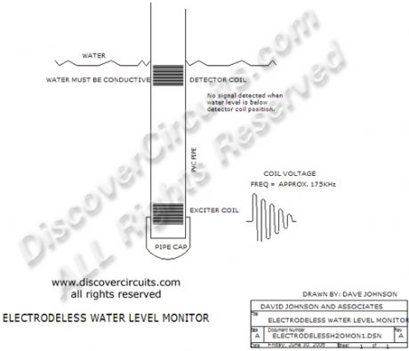
This system operates much like a classic float switch but without any moving parts. The illustration shows how a system using two copper coils sealed inside a plastic pipe, can detect the level of water outside the pipe. Whenever the water level is lower than the upper coil, no signal is coupled between the coils. Once calibrated, this technique might also work on the outside of a plastic water tank.
Source: discovercircuits (View)
View full Circuit Diagram | Comments | Reading(0)
Pot Controlled Variable LED Intensity Circuit -- September 24, 2009
Published:2012/9/6 20:09:00 Author:Ecco | Keyword: Pot Controlled, Variable LED Intensity
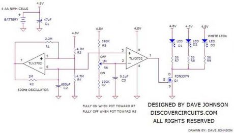
The circuit below uses power from four rechargeable AA NiMH cells to drive 3 white LEDs. A potentiometer varies the duty cycle of a pulse width modulator circuit to vary the intensity of the LEDs from 0% to 100%. The beauty of the circuit is that when the pot is all the way toward 0%, very little power is drawn from the battery. Likewise, when the pot slider is moved toward the 100% end, full power is fed to the LEDs. In effect, the pot becomes the on/off switch.
Source: discovercircuits (View)
View full Circuit Diagram | Comments | Reading(1159)
Computer Controlled 100ma Current Source (July 11, 2008)
Published:2012/9/6 20:06:00 Author:Ecco | Keyword: Computer Controlled , 100ma , Current Source

Often in industrial control systems a constant current source is needed, which is controlled by a computer and referenced to circuit ground. The circuit below converts a zero to 5v signal from a computer?s analog output into a current, with a full scale of 100ma. The circuit shown requires a 9v DC supply but any voltage from 9v to 12v will work.
Source: discovercircuits (View)
View full Circuit Diagram | Comments | Reading(0)
555 Timer Forms Simple PWM Motor Controller
Published:2012/9/6 20:00:00 Author:Ecco | Keyword: 555 Timer , Simple , PWM Motor Controller
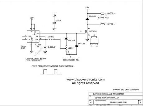
Using a CMOS version of the 555 timer, this circuit can be used to control the speed of a motor by adjusting the duty cycle of the pulses sent to the motor.
Source: discovercircuits (View)
View full Circuit Diagram | Comments | Reading(3407)
Neon colored lantern with music sound control circuit
Published:2012/9/5 22:29:00 Author:Ecco | Keyword: Neon colored lantern , music sound , control circuit
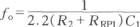
As shown in the figure, it is mainly composed of the multivibrator, graphics driver circuit, AC solid-state relay controller, songs sound circuit, amplifier circuit and AC buck rectifier circuit. It enables the 10 groups of neon lights to vagary with different lantern patterns, also accompanied by the world famous music. The time-base circuit 555 and R1 , R2 , C1 form a low-frequency harmonic oscillator, and its frequency: fo = 1.44 / (R1 + RRP1 +2 R2) C1. The oscillation frequency of the icon parameter is 0.035Hz to 0.15 Hz.
(View)
View full Circuit Diagram | Comments | Reading(1055)
LONG PERIOD COMPUTER WATCH DOG TIMER
Published:2012/9/5 20:53:00 Author:Ecco | Keyword: LONG PERIOD, COMPUTER WATCH DOG, TIMER
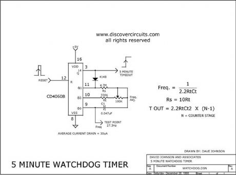
This circuit uses a simple 4060 IC oscillator/timer that is reset periodically by a computer. Should the computer fail to send a pulse, the output changes state. The time can easily be set from seconds to hours.
Source: discovercircuits (View)
View full Circuit Diagram | Comments | Reading(3083)
AC Line Under/Over Voltage Alarm (March 29, 2009)
Published:2012/9/5 20:51:00 Author:Ecco | Keyword: AC Line , Under/Over Voltage, Alarm

Power lines, which deviate much beyond normal voltages can damage expensive electronic equipment. The circuit below sounds an alarm whenever the line voltage is higher or lower than normal. I set the alarm limits at about +-15% from standard levels. The circuit rectifies and filters the power line signal. I set the resistor values, so the DC voltage produced is close to 1% of the RMS value of the line. Thus, a 120vac line would yield about 1.2v DC. That voltage is fed to a pair of voltage comparators.
Source: discovercircuits (View)
View full Circuit Diagram | Comments | Reading(2551)
CIRCUIT PROTECTS FROM BATTERY POLARITY REVERSAL
Published:2012/9/5 20:44:00 Author:Ecco | Keyword: CIRCUIT , PROTECTS , BATTERY POLARITY REVERSAL

This simple circuit can protect a sensitive electronic circuit from an accidental connection of a battery with a reversed polarity. The N-channel FET connects the electronic device to the battery only when the polarity is correct. The circuit shown was designed for a device powered from a single 1.5 volts button cell battery. However, the circuit will operate with higher voltages as well.
Source: discovercircuits (View)
View full Circuit Diagram | Comments | Reading(1285)
WATER SEEPAGE ALARM
Published:2012/9/5 20:44:00 Author:Ecco | Keyword: WATER SEEPAGE, ALARM
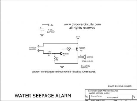
This simple circuit sounds a beeper when its electrodes detect water. It is powered by a single 1.5v N cell. A small 1.5v button battery will also work.
Source: discovercircuits (View)
View full Circuit Diagram | Comments | Reading(0)
| Pages:62/312 At 206162636465666768697071727374757677787980Under 20 |
Circuit Categories
power supply circuit
Amplifier Circuit
Basic Circuit
LED and Light Circuit
Sensor Circuit
Signal Processing
Electrical Equipment Circuit
Control Circuit
Remote Control Circuit
A/D-D/A Converter Circuit
Audio Circuit
Measuring and Test Circuit
Communication Circuit
Computer-Related Circuit
555 Circuit
Automotive Circuit
Repairing Circuit