
Control Circuit
Index 73
Water tank water level alarm circuit diagram
Published:2011/9/15 2:04:00 Author:Rebekka | Keyword: Water tank water level alarm
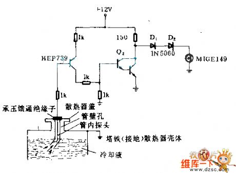
The insulator is stalledinto the lid of water tank. The insulator should suffer 0.717X10⁻⁴kg/m2 pressure from water tank. Metal probe passing the insulator is put into the liquid of water tank in the high temperature tube. There is small holes near to the one end of water tank lid. It can make the liquid rise in the tube and reach the probe. When the water level falls lower than the probe, the collector potancial of clad pipe Q2 rises and turns on the diode. The alarm M1 light will be lit. (View)
View full Circuit Diagram | Comments | Reading(2256)
Optocoupler switch circuit diagram
Published:2011/9/15 2:12:00 Author:Rebekka | Keyword: Optocoupler switch
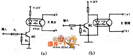
Figure 1 (b) shows off mode of the circuit. As no signal input, BG is stopped. When a signal is input, BG is conducted, due to BG's collector junction drops below 0.3V, which is much smaller than the light-emitting diode forward voltage, the light-emitting diode does not emit light without current flowing, then the resistance of a, b is large. It is equivalent to switch off . It is normally closed type. Visible, a, b ends are not limited by high or low potential in the circuit, but in theapplicationsof the circuit, we should make abe positive, b endbe negative, and U & ab> 3V, at the same time, Uab should be less than the BVceo of optical transistor.
(View)
View full Circuit Diagram | Comments | Reading(1338)
Electric fan natural wind control circuit diagram
Published:2011/9/26 1:11:00 Author:Rebekka | Keyword: Electric fan, natural wind control
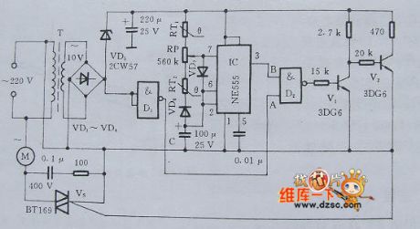
The nucleus of electric fan natural wind control circuit is an indirect feedback astable multivibrator. The circuir is composed of time-base integrated circuit and PTC thermistor, NTC thermistor.
Indirest feedback type astable multivibrator circuit.
2.5.2 The main device choice.
The fan natural wind autoregulate circuit uses RT1 NTC thermistor with B value in 5600K. Room temperature resistor is 51KΩ; RT2's room temperature is20~30℃, temperature coefficient is 12%/℃, room temperature resistance is 470KΩ. C should choose good insulation and small leakage current Tantalum electrolytic capacitor. CD6, VD7 choose small reverse current switch diode. The choice of VS is decided by the power of the electric fan. It is available for the 60W below fan.
(View)
View full Circuit Diagram | Comments | Reading(1996)
Lightning protection circuit diagram for equipments
Published:2011/9/25 21:22:00 Author:Ecco | Keyword: Lightning protection , equipments
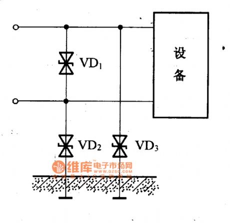
When lightning occurs and generates the overvoltage, the over-voltage current can pass transient voltage between lines and ground to suppress diodes VD2, VD3 from connecting to the earth, and their ground voltage difference is further inhibited by the bipolar transient voltage suppression diode VD1 between two lines, so that the equipment is protected.
(View)
View full Circuit Diagram | Comments | Reading(1791)
TV lightning protection circuit diagram
Published:2011/9/25 21:29:00 Author:Ecco | Keyword: TV lightning protection
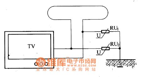
If you watch TV in thunderstorm days, lightning will damage the TV tuner by outdoor antenna. If you install the varistor in outdoor antenna, it may play a role on lightning protection. TV lightning protection circuit is shown as the chart, varistors can connect directly with the earth.
(View)
View full Circuit Diagram | Comments | Reading(2082)
Rectifier over-current protection circuit diagram
Published:2011/9/25 21:36:00 Author:Ecco | Keyword: Rectifier , over-current protection
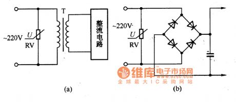
As the voltage fluctuations or man-made distribution incidents often make the power grid generate surge over-voltage phenomenon, then the electronic equipments and power transformer rectifier circuit will be damaged. If varistor is connected to the input end of rectifier diodes and power transformer to play a protective role. The circuit is shown as the chart.
(View)
View full Circuit Diagram | Comments | Reading(1674)
Automatic interval timer circuit composed of PUT
Published:2011/9/13 2:04:00 Author:Rebekka | Keyword: Automatic interval timer
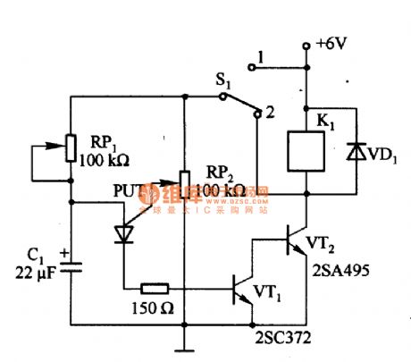
Figure 1 is composed of the PUT and other automatic interval timer circuit. In the circuit, PUT is the oscillator. Using the switch S1 to switchover the interval time and automatic time. When S1 connects to 1, it is automatic timing mode 1, thenS1connects to2, itis the interval time. If the resistance of RP2is too large, PUT anode current is less than the maintenance current, the circuit can not be used as the automatic timing circuit. (View)
View full Circuit Diagram | Comments | Reading(2330)
Electric fence control circuit 6
Published:2011/8/1 3:03:00 Author:Ecco | Keyword: Electric fence control
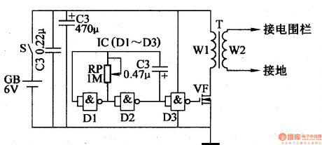
The electric fence control circuit is composed of the power supply circuit, oscillator and pulse voltage output circuit, and it is shown in Figure 4-31. Power supply circuit is composed of the battery GB, power switch S and capacitors Cl, C2. Oscillator is composed of the NAND gates Dl, D2 which are inside of NAND gate IC (Dl-D3 are connected as the NOT gate) and potentiometer RP, capacitor C3. Pulse voltage output circuit is composed of the internal D3 of IC NAND gate, field-effect transistor VF and pulse transformer T.
(View)
View full Circuit Diagram | Comments | Reading(2529)
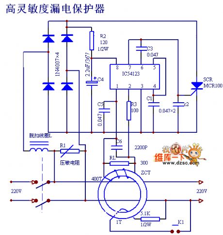
High sensitivity leakage protector circuit diagram
Published:2011/9/14 22:10:00 Author:Rebekka | Keyword: Leakage protection, leakage protector
View full Circuit Diagram | Comments | Reading(1352)
Light audio controlling touching circuit diagram
Published:2011/9/14 22:23:00 Author:Rebekka | Keyword: Light , audio controlling touching
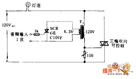
Three-terminal two-way SCRis controlled bylampon - off set. Two-way SCR is triggered by 1v audio signal. T1 is an isolation transformer. Since the action of switching is much faster than the reaction of light bulbs and the human eyes. The effect of the audio control is similar to the proportional control. When resistor R1 is set to the maximum input is zero. But bulb can not do that. Three-terminal two-way SCR should match to the bulb.
(View)
View full Circuit Diagram | Comments | Reading(916)
The eggs hatching incubator circuit diagram 1
Published:2011/9/18 21:15:00 Author:Ecco | Keyword: Eggs hatching incubator
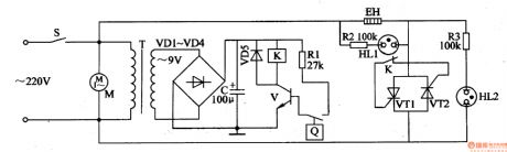
The eggs hatching incubator circuit is composed of the power supply circuit, temperature detection control circuit and indication circuit, and it is shown in Figure 4-4. Power supply circuit consists of the power switch S, power transformer T, rectifier diodes VDl-VD4 and filter capacitor C. Temperature detection control circuit consists of electric contact thermometer Q, resistor Rl, transistor V, Relay K, diode VD5, thyristors VT1, VT2, and the fan motor M. Indicating circuit consists of resistors R2, R3 and neon lights HLl, HL2. Rl-R3 select the 1/4W metal film resistors. C select the aluminum electrolytic capacitor with voltage in 25V.
(View)
View full Circuit Diagram | Comments | Reading(2127)
Music controlling circuit diagram
Published:2011/8/31 2:46:00 Author:Rebekka | Keyword: Music controlling circuit
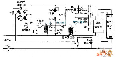
The circuit can drive 10 pieces of 40W fluorescent lamps. When K2 is closed, the brightness of the light will change the audio signal amplitude.Because fluorescent lamp has not the time delay effect like incandescent lamp, the music can control the light of dance hall accurately and timely. (View)
View full Circuit Diagram | Comments | Reading(741)
Earthquake sound and light alarm circuit
Published:2011/9/14 21:06:00 Author:Rebekka | Keyword: Earthquake , sound and light , alarm

The circuit is composed of two integrated circuit chips as the core, and it has few external components, but experiments show the favorable results. It's the circuit is shown as the chart. 555 and R2, C1 form a monostable trigger, usually due to the small copper hammer is floating isolated, the pin 2 of 555 is connected to high potential Vnn by R1, thus making 555 be in a reset state, that is, pin 3 outputs low, then the backward stage does not work without electricity. HFC5212 is the high level trigger, and the quiescent current is very small, the working output current I0 is about 1mA, which can directly drive medium, low power tube.
(View)
View full Circuit Diagram | Comments | Reading(739)
btl circuit theory and circuit diagram
Published:2011/9/12 22:21:00 Author:Rebekka | Keyword: btl circuit theory
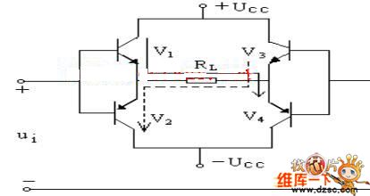
The working theory circuit diagram is shown as above. There is no direct current in load RL. In the positive half cycle of the ui, the top is positiveand down is negative, V1 and V4 areturned on, V2 and V3 stop, the current passing load RL is shown as the real line in the figure; In the negative halfcycle of the ui, negative is on the top and down is the positive, V1 and V4 stop, V2 and V3 turn on, the current passing load RL is shown as the dotted line in the figure. Ignore saturation voltage, two halfs cycles will be compounded. It can get output signal voltagewith width in UCC from load. (View)
View full Circuit Diagram | Comments | Reading(809)
Integrated counter timer timing circuit composed of XR2240
Published:2011/8/22 22:33:00 Author:Rebekka | Keyword: Integrated counter timer, timing circuit

XR2240 is an integrated counter timer. It is an improved device based on 555. It includes an oscillator composed of 555, eight divider and control logic circuit. The XR2240 block diagram and timing diagram is shown as above.
(View)
View full Circuit Diagram | Comments | Reading(2242)
Plastic recycling machine control circuit diagram
Published:2011/9/16 1:51:00 Author:Ecco | Keyword: Plastic recycling machine, control circuit
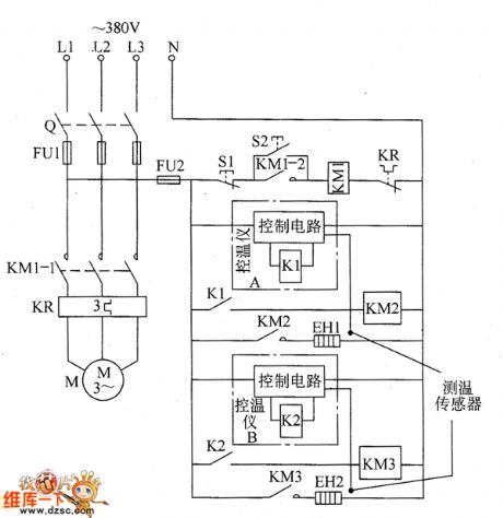
The plastic recycling machine control circuit is composed of the main control circuit of the motor and heater temperature control circuit, and it is shown as the chart. The main control circuit of the motor is composed of the knife switch Q, fuses FU1 and FU2, AC contactor KM1, thermal relay KR, stop buttons S1, S2 and motor start button M. Heater temperature control circuit is composed of the AC contactors KM1 and KM2, temperature control device A, temperature control device B, plastic preheating ring heater EH1 and melting electric heater EH2. KM2 and KM3 use the AC contactors with coil voltage in 220V.
(View)
View full Circuit Diagram | Comments | Reading(1609)
The temperature controller circuit diagarm 2
Published:2011/9/18 21:15:00 Author:Ecco | Keyword: Temperature controller
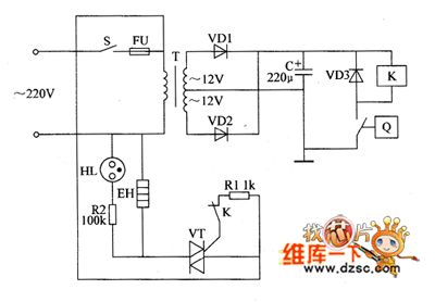
The temperature controller is composed of the power supply circuit and temperature detection control circuit, and it is shown as the chart. Power supply circuit is composed of the power switch s, fuse FU, power transformer T, rectifier diodes VDI, VD2 and filter capacitor C. Temperature measurement control circuit is composed of electric hot thermometer Q, relay Κ, diode VD3, resistors RI, R2, thyristor VT, neon light HL and electric heater EH. RI and R2 use the 1/4W carbon film resistors or metal film resistors.
(View)
View full Circuit Diagram | Comments | Reading(801)
Cycle timing controller 5
Published:2011/8/9 20:15:00 Author:Ecco | Keyword: Cycle timing controller
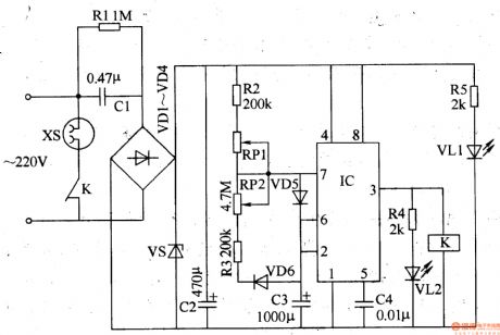
The cycle timing control circuit is composed of the power supply circuit and timing control circuit, and it is shown in Figure 3-93. The power supply circuit is composed of the step-down capacitor Cl, resistors Rl, R5, rectifier diodes VDl-VD4, voltage regulator diode VS, power indicator LED VLl and filter capacitor C2. Timing control circuit consists of the time-base IC, resistors R2-R4, capacitor C3, potentiometers RPl, RP2, diodes VD5, VD6, light-emitting diode VL2 and relay K. Rl selects the 1/2W carbon film resistor; R2-R5 use 1/4W carbon film resistors or metal film resistors. RP1 and RP2 select the small linear synthetic membrane potentiometers.
(View)
View full Circuit Diagram | Comments | Reading(1256)
Electric oven temperature controller
Published:2011/8/9 20:14:00 Author:Ecco | Keyword: Electric oven , temperature controller

The electric oven temperature controller circuit is composed of the power supply circuit and temperature detection control circuit, and it is shown in Figure 3-80. Power supply circuit is composed of the power switch S, fuse FU, power transformer T, rectifier diodes VDl, VD2 and filter capacitor C. The temperature detection control circuit is composed of electric hot thermometer Q, relay K, diode VD3, resistors Rl, R2, Crystal thyristor VT, neon light HL and electric heater EH. Rl and R2 use the 1/4W carbon film resistors or metal film resistors. C selects the aluminum electrolytic capacitor with voltage in 25V. VDl-VD3 use the 1N4007 silicon rectifier diodes.
(View)
View full Circuit Diagram | Comments | Reading(4481)
Automatic feed controller
Published:2011/8/9 20:14:00 Author:Ecco | Keyword: Automatic feed controller
The automatic feed controller circuit is composed of the power supply circuit, pulse oscillator, electromagnetic control circuit and motor control circuit, and it is shown in Figure 4-42. Power supply circuit is composed of the knife switch Q, fuses FUl-FU3, buck capacitors Cl, C2, discharge resistor Rl, control switch S, relay K, rectifier diode VDl, voltage regulator diode and filter capacitor C3. Pulse oscillator is composed of the resistor R6, potentiometers RPl, RP2, diodes VD3, VD4, capacitor Cl2 and time-base IC. Solenoid control circuit consists of the electromagnet YA, resistors R7-R9, RI3, potentiometer RP3, diodes VD2, VD5, transistor V, capacitor C5 and thyristor VTl.
(View)
View full Circuit Diagram | Comments | Reading(798)
| Pages:73/312 At 206162636465666768697071727374757677787980Under 20 |
Circuit Categories
power supply circuit
Amplifier Circuit
Basic Circuit
LED and Light Circuit
Sensor Circuit
Signal Processing
Electrical Equipment Circuit
Control Circuit
Remote Control Circuit
A/D-D/A Converter Circuit
Audio Circuit
Measuring and Test Circuit
Communication Circuit
Computer-Related Circuit
555 Circuit
Automotive Circuit
Repairing Circuit