
Control Circuit
Index 76
OPA603 Constituted Low-pass Filter Circuit Of 10MHz
Published:2011/8/12 4:54:00 Author:Felicity | Keyword: Low-pass Filter, 10MHz
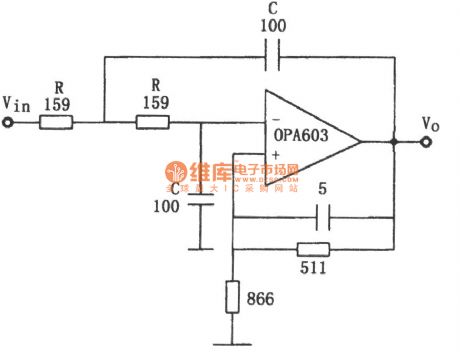
The circuit is showed in the picture. The circuit makes use of Second-order Butterworth low-pass filter. The fillter is made of high-speed current feedback operational amplifier OPA603 with broadband of 100MHZ. The transition frequency is f0=1/2πRC. The parameter is showed in the picture.f0=10MHz. Circuit gain is 1.6.
(View)
View full Circuit Diagram | Comments | Reading(1376)
Low-end Car Charger Circuit Diagram Achieved by Single Chip 34063
Published:2011/9/3 10:13:00 Author:Zoey | Keyword: Low-end, Car Charger, Single Chip 34063
Advantage: Low cost
Disadvantage:
(1) Undesirable reliability, single performance, no overtemperature and short circuit-proof measures.
(2) Inputs direct current voltage, but controls input constant charge current by limiting maximum switched current peak, its precision is not accurate enough.
(3) As 34063 belongs to a 1.5-A switched current PWM+PFM mode (no interior error magnifier), its automobile charge inputs relatively larger wave of direct voltage and current, the wave is not pure enough and its ability to input current is limited. (often been seen in low-end automobile charge ranging from 300 ma to 600 ma) (View)
View full Circuit Diagram | Comments | Reading(872)
FET Time Relay Circuit
Published:2011/9/3 10:01:00 Author:Zoey | Keyword: FET, Time Relay
FET Time Relay Circuit (View)
View full Circuit Diagram | Comments | Reading(1057)
Single stage power factor dimming type fluorescent lamp electronic ballast design
Published:2011/9/4 20:39:00 Author:TaoXi | Keyword: Single stage, power factor, dimming type, fluorescent lamp, electronic ballast design
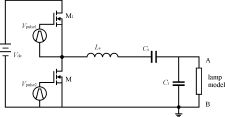
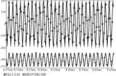
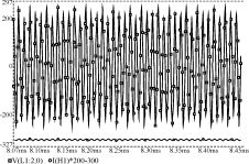
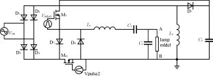
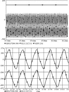
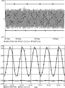

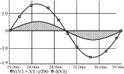
The frequency control means to change the fs switching frequency, so the operating frequency is away from the natural resonant frequency of the resonant network to reduce the lamp power, at this time, the duty cycle D is constantly. The duty cycle modulation means that when the fs is constantly, you change the conduction time of the switch, the reduction of the conduction time reduces the energy that is delivered to the lamp, so the power of the light reduces. The duty cycle modulation range is from 0 to 0.5, so it limits the dimming range. The DC bus voltage regulation means that you can change the amplitude value of the DC bus voltage, and keep the fs and D unchanged.
(View)
View full Circuit Diagram | Comments | Reading(819)
BAX type tone control circuit
Published:2011/9/4 20:45:00 Author:TaoXi | Keyword: BAX, tone control
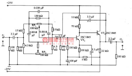
The BAX type tone control circuit is as shown in the figure. This kind of circuit has low output impedance and input impedance, if the prestate output impedance is not lower enough, you can not get the desired characteristics. The control potentiometer need to use the B-type potentiometer.
(View)
View full Circuit Diagram | Comments | Reading(1552)
A Time Circuit Diagram for Improving Anti-jamming Performance
Published:2011/9/3 10:33:00 Author:Zoey | Keyword: Time Circuit Diagram, Anti-jamming Performance
A Time circuit diagram for improving anti-jamming performance has been shown in following picture. In practical, high-frequency spark jamming, electromagnetism jamming as well as the absorption and release of relays often do harm to the circuit. This circuit has strong anti-jamming performance. BG3 and 2DW7 constitute a step-down voltage circuit, interfere the filter of 24V power supply. After increasing the magnitude of trigger pulse, BG1 and DW2 will constitute a high threshold inverting amplifier, small-magnitude jamming pulse will be prevented.BG2 and other resistances and capacitors are used to filter narrow pulse jamming. (View)
View full Circuit Diagram | Comments | Reading(785)
A One-hour Timer Circuit
Published:2011/9/3 10:34:00 Author:Zoey | Keyword: One-hour, Timer Circuit
The one-hour timer circuit has been shown in following picture. This circuit adopts high input resistance FET to input operational amplifier 3140, so as to add timing scale of 555 timer to its 100 times. Choose proportion of R3/R2 to change the multiplier index. Delay time is T=[(R2+R3)/R2] (1386R1C1), parameter in the picture is T=100R1C1= 1 hour. (View)
View full Circuit Diagram | Comments | Reading(1402)
A Passive Light-controlled Switched Circuit Diagram
Published:2011/9/3 19:59:00 Author:Zoey | Keyword: Passive, Light-controlled, Switched Circuit Diagram
Following picture shows the passive light-controlled switched circuit. Generally, light-controlled switches need power supply. Although integrated light-controlled controllable silicon switches do not need power supply, they have to satisfy the requirements such as high sensitivity and high pressure resistance. Circuit (a) is a passive light-controlled direct current switch, therein, 2CR1 and 2CR2 are closed gate high-speed light cell, they are used to receive light signals, produce voltage and input current. Circuit (b) is a passive light-controlled AC switch, if the load current is not large enough, it can set the load on AC trigger directly and it can work without the AC trigger.
(View)
View full Circuit Diagram | Comments | Reading(743)
The infrared alarm system circuit
Published:2011/8/24 21:31:00 Author:Christina | Keyword: infrared, alarm system
The infrared alarm system circuit is as shown in the figure. (View)
View full Circuit Diagram | Comments | Reading(920)
Infrared control automatic faucet composed of the NE555 and LM567
Published:2011/9/8 19:58:00 Author:Christina | Keyword: Infrared control, automatic, faucet
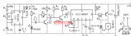
The infrared control automatic faucet has the same control principle with the infrared control automatic hand dryer. The infrared control automatic hand dryer is used to control the on and off of the electric blower, but the infrared control automatic faucet is used to control the on and off of the electromagnetic water valve. Here I introduce the infrared control automatic faucet, the composition is as shown in the figure. This circuit is composed of the infrared transmitter, the infrared receiver amplifier and the valve switch controller.
(View)
View full Circuit Diagram | Comments | Reading(2399)
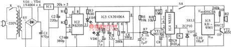
Infrared remote control delay power saving switch composed of the CX20106 and NE555
Published:2011/9/8 20:00:00 Author:Christina | Keyword: Infrared, remote control, delay, power saving, switch
The circuit is composed of the special infrared receiving demodulation integrated circuit CX20L06 and the NE555 circuit, this circuit uses the two-way thyristor as the switch of the light. It is the fully integrated infrared remote control switch circuit, the structure is as shown in the figure.
(View)
View full Circuit Diagram | Comments | Reading(1643)
RCC Power Practical Circuit Using Synchronous Rectification
Published:2011/8/23 22:06:00 Author:Robert | Keyword: RCC, Power, Practical, Synchronous, Rectification
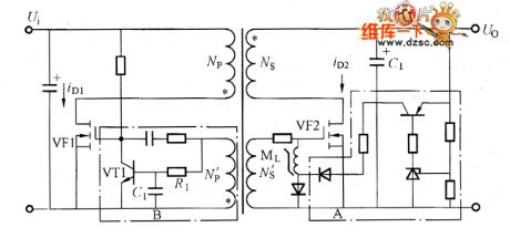
The RCC power practical circuit by using synchronous rectification is shown in the picture. In the picture's dotted frame A, it is the control circuit which controls thereset currentto go through the saturable reactor ML. The output voltage is higher than the setting value, the reset current would increase. The larger of the reset current, the longer the time during ML to saturable would be. And also the wider the synchronous pulse width which is added to the secondary MOSFET (VF2) grid electrode would be. And the longer the conducted time of the secondary MOSFET would be. If the secondary MOSFET's conducted time is changed to be longer, even the transformer's flyback energy is fully released, the secondary MOSFET could also keep the conducted mode. The secondary smoothing capacity C1's voltage is added on the secondary winding and it would have the reverse excitation for the transformer. (View)
View full Circuit Diagram | Comments | Reading(1118)
The magnetic eraser energy-saving controller
Published:2011/8/23 22:36:00 Author:qqtang | Keyword: magnetic eraser, energy-saving controller
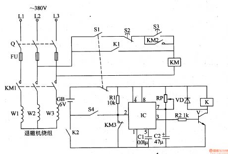
The working principle of the circuit
The magnetic eraser energy-saving controller circuit consists of the relay K, transistor V, time-based integrated circuit IC, diode VD, resistors of R1 and R2, potentiometer RP, capacitors of C1 and C2, battery GB, stroke switch and hand/auto control switch S1 and so on, see as figure 8-147.
All the knife-switch Q, starting key S3, stop key S2 and AC contactor KM are the former hand control line of the magnetic eraser.
When it is under auto control, the control switch S1 is reset (auto), at the moment, the normally closed contactor is getting through, the normally open contactor is turned off, the control circuit isn't working because of the breaking down of the negative pole.
(View)
View full Circuit Diagram | Comments | Reading(1506)
Overheating Protection Circuit (using PTC thermistor)
Published:2011/5/17 21:17:00 Author:Sharon | Keyword: Overheating Protection, PTC thermistor
For continuously operating mechanical and electrical equipment used in production like automatic lathes, electric oven, and ball mill and other and other unattended devices, due to the motor overheating or accident caused by thermostat failures have occurred not rare, it's necessary to take appropriate security measures. PTC thermistor overheating protection circuit can be easily and effectively to prevent such incidents from occurring.
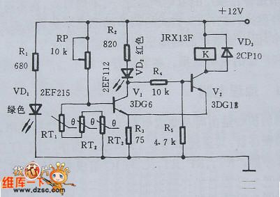
1. Principle circuitFigure 1 is an example of motor overheat protection. It's a control circuit composed bythe PTC thermistor and the Schmitt circuits. In the figure, RT1, RT2 and RT3 are three step-type PTC thermistors of the same characteristics. They were buried in the stator windings. Under normal circumstances, PTC thermistor is in room temperature, and their total resistance is less than 1KΩ. At this point, V1 pauses, V2 turns on, and the relay K is through and open normally. The motor is powered by city electricity.
Figure 1 Motor overheating protection control circuit
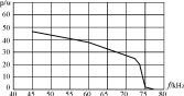
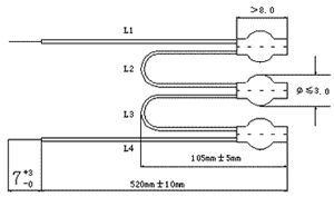
2. The main components election The choice of PTC thermistor depends on the motor insulation class. Components dimensions are shown in Figure 2. Usually, the choice of Curie temperature of PTC thermistor is 40℃ lower than the limit temperature which corresponds to the motor insulation level.
Figure 2 PTC thermistor Dimensions
3 Installation and adjustmentThe recommended installation way is to bury PTC thermistor in the stator windings. Adjustment method: Put PTC thermistor in incubators, set the temperature TK, regulate RP to make that when PTC thermistor stays at TK-5 ℃, VD2 does not shine, K does not move; while when it stays at TK +5 ℃, VD2 lights, K acts. RP can be locked.
(View)
View full Circuit Diagram | Comments | Reading(3370)
Electric Blanket Temperature Control Circuit
Published:2011/5/17 4:35:00 Author:Sharon | Keyword: Electric Blanket, Temperature Control
Electric blanket without temperature controller not only can hardly obtain a comfortable bed temperature, but also has huge energy consumption. What's worse, there may be fire hazard. Electric blanket with bimetallic thermostat although has improvements in energy-saving and security, but it's still difficult for it to adjust the temperature. Temperature control circuit with a PTC thermistor can overcome these shortcomings.
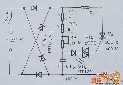
1. Principle circuit The electric blanket temperature control circuit is consistuted by the rectifier circuit and the temperature measurement and control circuit. Its principle is shown in Figure 2.11.1. Chart, RT1 and RT2 are the PTC thermistor for detecting the temperature of different regions, and also form a SCR VS trigger circuit together with the RP, C and VD6. RP also has the function of defaulting the constant temperature values.
2. Main components selectionPTC thermistor should be selected with Curie temperature 30 ℃, temperature resistance 5KΩ, and withstanding voltage 500V or more. VS should be chosen by the size of RL power. The circuit model selected here can meet the general use of electric blankets. C selects the best insulation performance polycarbonate film capacitors.
3. Installation and adjustmentThe recommended installation method is burying two PTC thermistors in the intensive sites of the electric wires. For example, the center of the feet and waist. In addition, the circuit is connected directly with the city electricity, and the PTC thermistor buried in the electric blanket and its terminations should have good insulation measures.
(View)
View full Circuit Diagram | Comments | Reading(5124)
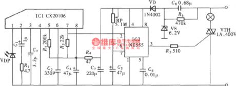
Disinfection cabinet electronic control circuit
Published:2011/9/8 20:01:00 Author:Christina | Keyword: Disinfection cabinet, electronic control circuit
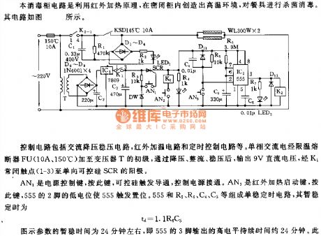
The control circuit is composed of the AC step-down regulator circuit, the infrared heating circuit and the timing control circuit. The single phase alternating current adds to the primary stage of the transformer T through the temperature limit fuse FU, and it is reduced, rectified and stabilized by the circuit to change into the 9V DC voltage, this DC voltage adds to the positive pole of the one-way SCR through the normally closed contact point K1(1-3).
The AN1 is the power control button, you can conduct the SCR and control the connection of the power supply by pressing this button. AN3 is the infrared heating start button, if you press this button, the low level of the 555's pin-2 will make the 555 in the trigger & set state. The monostable timing circuit is composed of the 555 and R5, R6, C4, C5.
(View)
View full Circuit Diagram | Comments | Reading(903)
Microwave detection radio alarm 26P27
Published:2011/9/8 19:55:00 Author:TaoXi | Keyword: Microwave, detection, radio alarm
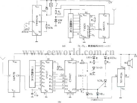
In figure (a), when the detection circuit TWH9250 detects the target signal, the output port 0 of it outputs the low level, the relay K is connected. When the transmitter circuit gets the operating power supply, the address code which is edited by the coding circuit YYH26 is amplified by the ampP27A, and it is output by the antenna. The detection circuit can be used to connect the operating power supply of the transmitter, the transmitter circuit outputs the address code to indicate the detection place. Figure (b) shows the multi-channel receiver alarm circuit.
(View)
View full Circuit Diagram | Comments | Reading(1023)
Rotating monitor circuit
Published:2011/9/8 20:20:00 Author:Christina | Keyword: Rotating monitor
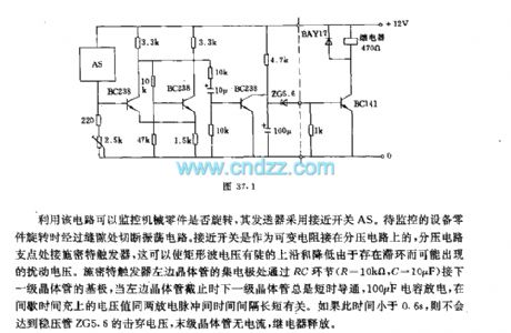
This circuit can be used to monitor the rotation of the mechanical part, the transmitter uses the approach switch AS. When the mechanical part is rotating, the switch cuts off the oscilation circuit through the gap. The approach switch AS can be used as the variable resistor which is connected with the voltage divider circuit, the fulcrum of the voltage divider circuit is connected with the Schmidt trigger, the trigger can make the square-wave voltage have the rising edge and the down edge, the hysteresis loop can produce the disturbance voltage. The left transistor's collector electrode of the Schmidt trigger is connected with the base electrode of the next transistor through the RC.
(View)
View full Circuit Diagram | Comments | Reading(941)
LAN (Ethernet) controlling AD ADC, analog data acquisition module
Published:2011/9/8 3:11:00 Author:Lucas | Keyword: LAN , Ethernet, controlling , AD ADC, data acquisition module
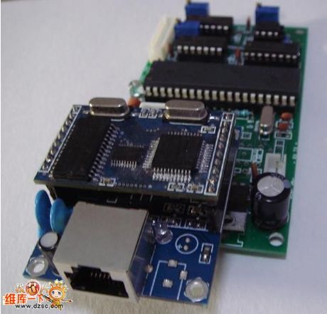
The local area network (Ethernet) controlling AD ADC / analog data acquisition module uses TCP / IP protocol and control host (PC) to communicate, and it is stable and reliable. Transmission distance is far ( it is up to 300 meters through the switch cascaded, even through it can the remote control by the Internet), each AD conversion / data acquisition board is assigned an unique IP address, and it makes data transmission and distinction by IP address; the controlled AD conversion / data acquisition board has a large number (IP address range: 192.168.1. 1 ~ 192.168.1.254, you can drive total of 254 AD conversion / data acquisition boards). The control panel has 6 channels of 10-bit (precision is ± 1LSB) high-speed A / D converter channels.
(View)
View full Circuit Diagram | Comments | Reading(1137)
Schematic diagram of clock circuit composed of AT89C2051
Published:2011/9/7 4:15:00 Author:Vicky | Keyword: schematic diagram, clock circuit
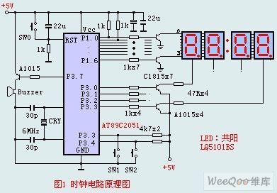
The circuit composition determines that the LED adopts anodic Nixie tube. It can use LQ5101BS general luminous diode and the driving triode can use 2SA1015 or 2SC1815 types which is easy to gain. Of cause, the triode can also use low-power triode such as S9012, S9013,S9014,2N5401,and 2N5555 etc. There are no special requirements for other components. To make the experiment easier, monolithic AT89C2051 can use DIP20P socket. The program need no debugging after written, and it can be copied to AT89C2051. What worth mentioning is that AT89C2051 is a flash program memorizer, and the program can be rewritten repeatedly, which makes it very easy to conduct experiments. (View)
View full Circuit Diagram | Comments | Reading(9192)
| Pages:76/312 At 206162636465666768697071727374757677787980Under 20 |
Circuit Categories
power supply circuit
Amplifier Circuit
Basic Circuit
LED and Light Circuit
Sensor Circuit
Signal Processing
Electrical Equipment Circuit
Control Circuit
Remote Control Circuit
A/D-D/A Converter Circuit
Audio Circuit
Measuring and Test Circuit
Communication Circuit
Computer-Related Circuit
555 Circuit
Automotive Circuit
Repairing Circuit