
Digital Circuit
Index 7
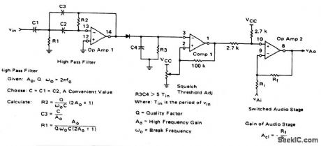
SQUELCH_CIRCUIT_FOR_AM_OR_FM
Published:2009/6/26 3:50:00 Author:May
View full Circuit Diagram | Comments | Reading(0)
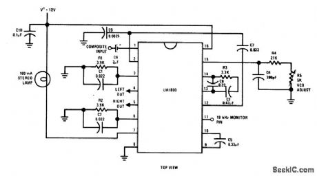
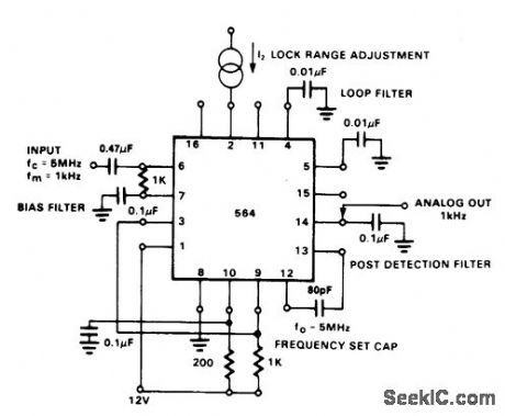
FM_STEREO_DEMODULATION_SYSTEM
Published:2009/6/26 3:40:00 Author:May
View full Circuit Diagram | Comments | Reading(703)
COMBINATION_VOLTAGE_AND_CURRENT_REGULATOR
Published:2009/6/26 3:35:00 Author:May
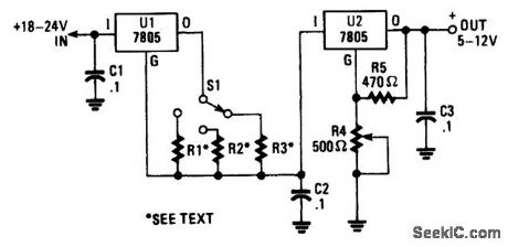
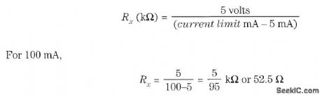
This voltage-regulator/current-limiter combination can be made from two 7805 regulators as shown. R1, R2, and R3 should be selected for a 5-V drop at the maximum allowable current limit. S1 selects one of the three current values. Do not forget that U1 requires 5 mA to operate and this means that the minimum current limit setting should be 10 mA or more (R1 = 1.25 kΩ). Resistor values are as follows: (View)
View full Circuit Diagram | Comments | Reading(819)
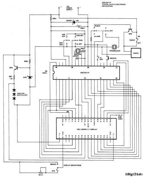
CLOCK_RADIO
Published:2009/6/26 3:14:00 Author:May
View full Circuit Diagram | Comments | Reading(935)
BEAM_SPLITTER_FOR_OSCILLOSCOPE
Published:2009/6/26 2:27:00 Author:May
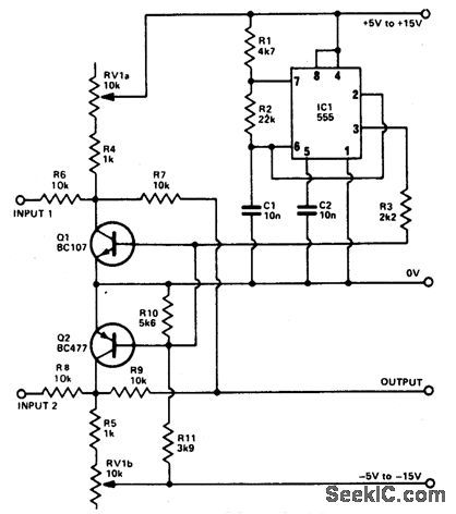
The basis of the beam splitter is a 555 timer connected as an astable multivibrator.Signals at the two inputs are alternately displayed on the oscilloscope with a clear separation between them. The output is controlled by the tandem potentiometer RV1a/b which also varies the amplitude of the traces. (View)
View full Circuit Diagram | Comments | Reading(852)
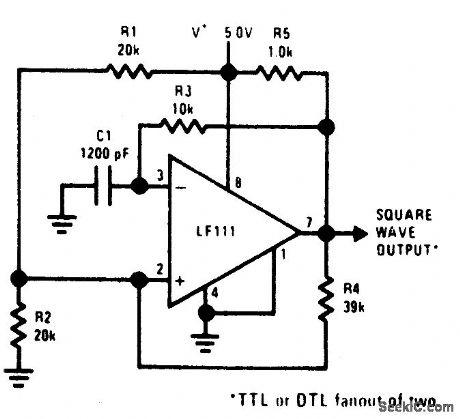
100_kHz_FREE_RUNNING_MULTIVIBRATOR
Published:2009/6/26 2:08:00 Author:May
View full Circuit Diagram | Comments | Reading(714)
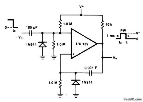
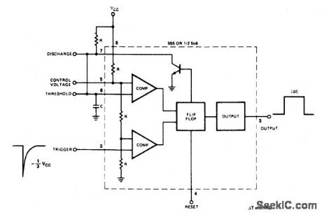
MONOSTABLE_MULTIVIBRATOR
Published:2009/6/26 2:08:00 Author:May
View full Circuit Diagram | Comments | Reading(0)
BISTABLE_MULTIVIBRATOR
Published:2009/6/26 2:07:00 Author:May
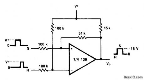
View full Circuit Diagram | Comments | Reading(0)
ONE_SHOT_MULTIVIBRATOR_
Published:2009/6/26 2:07:00 Author:May
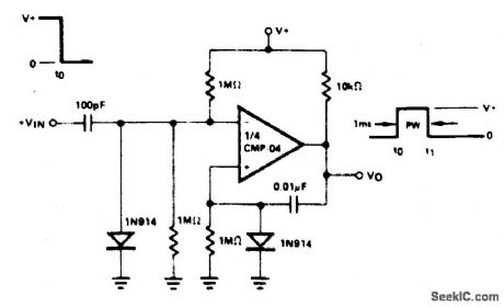
View full Circuit Diagram | Comments | Reading(902)
1MONOSTABLE_CIRCUIT
Published:2009/6/26 2:04:00 Author:May
View full Circuit Diagram | Comments | Reading(632)
UJT_MONOSTABLE
Published:2009/6/26 2:02:00 Author:May
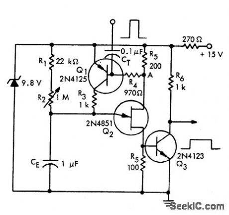
View full Circuit Diagram | Comments | Reading(637)
DUAL_ASTABLE_MULTIVIBRATOR
Published:2009/6/26 2:02:00 Author:May
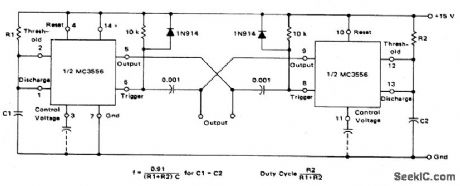
This dual astable multivibrator provides versatility not available with single timer circuits. The duty cycle can be adjusted from 5% to 95%. The two outputs provide two phase clock signals often required in digital systems.It can also be inhibited by use of either reset terminal. (View)
View full Circuit Diagram | Comments | Reading(716)
DIGITAL_THERMOMETER
Published:2009/6/26 1:41:00 Author:May
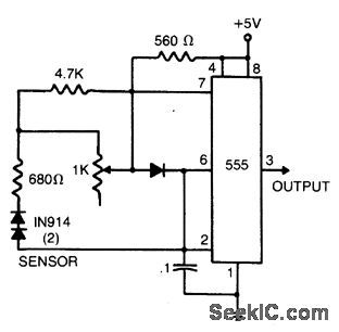
The sensor consists of two series-connected 1N914s, part of the circuit of a 555 multivibrator. Wired as shown, the output pulse rate is proportional to the temperature of the diodes. This output is fed to a simple frequency-counting circuit. (View)
View full Circuit Diagram | Comments | Reading(796)
PRECISION_FULL_WAVE_RECTIFIER
Published:2009/6/25 23:42:00 Author:May
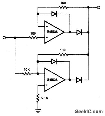
Circuit Notes
The circuit provides accurate full wave rectification. The output impedance is low for both input polarities, and the errors are small at all signal levels. Note that the output will not sink heavy current, except a small amount through the 10 K resistors. Therefore, the load applied should be referenced to ground or a negative voltage. Reversal of all diode polarities will reverse the polarity of the output. Since the outputs of the amplifiers must slew through two diode drops when the input polarity changes, 741 type devices give 5% istortion at about 300 Hz. (View)
View full Circuit Diagram | Comments | Reading(0)
AC_MOTOR_BRAKE
Published:2009/6/25 23:37:00 Author:May
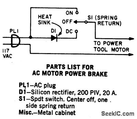
A shot of direct current will instantly stop any ac power tool motor. Switch S1 is a center-off, one side spring return. With S1 on, ac will be fed to the motor and the motor will run. To brake the motor, simply press S1 down and a quick shot of dc will instantly stop it. The switch returns to the center off position when released. This Power Brake can only be used with ac motors; it will not brake universal (ac-dc) motors. A heat sink must be provided for the diode. (View)
View full Circuit Diagram | Comments | Reading(0)
FM_DEMODULAT0_R_AT_12_V__
Published:2009/6/25 23:28:00 Author:May
View full Circuit Diagram | Comments | Reading(0)
80_METER_DIRECT_CONVERSION
Published:2009/6/25 23:28:00 Author:May
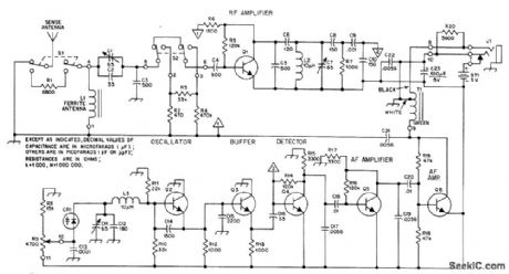
Portabl e receiver with directional ferrod antenna and ver-tical sense antenna was developed for radio foxhunting at 1975 Bov Scout World Jamboree in Norway, in competitions for locating four low-power crystal-controlled transmitters hid-den along 4-km course. Varactor-tuned oscillator provides 20-kHz tuning range with R9, ade-quate for the frequency used-3.566, 3.585, 3.635, or 3680 MHz. T1 is subminiature auto-transformer with 8-ohm and 2000-ohm sec-tions, for 8-ohm headphones. For high-imped-ance headphones, connect headphone jack J1 to lug 9 of T1. ON/OFF switch is not needed, L1 is 22 turns No. 28 enamel wound over two 10×95 mm ferrite rodstaped together. 01-06 are NPN high-frequency small-signal transistors.-N. K. Holter, Radio Foxhunting in Europe, QST, Nov. 1976, p 43-46. (View)
View full Circuit Diagram | Comments | Reading(0)
5_STEP_ATTENUATOR
Published:2009/6/25 23:27:00 Author:May

AppIication s indude comparing performance of various rece Mng an-tennas and measuring gain of preamp used abead of receiver. Dashed lines represent required shield partitions. All resistors are 1/4-W composition with 5% tolerance.-D.DeMaw, What Does My S-Meter Tell Me?, QST,June 1977,p 40-42. (View)
View full Circuit Diagram | Comments | Reading(0)
SELF_EXCITED_SWR_BRlDGE
Published:2009/6/25 23:19:00 Author:May
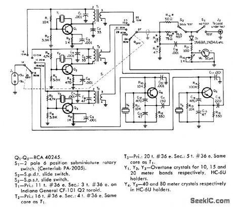
Portable bridge has built-in signal sources for each band from 80 through 10 meters, for tuning antenna on tower before transmission line is connected.Oscillators are crystal controlled at desired antenna tuneup frequencies. Separate oscillators for each band simplify switching problems, so only supply voltage from J1 and oscillator outputs to meter circuit need be switched. Current drain from 9-V battery is maximum of 12 mA.R17 and R18 should be closely matched, while R1, and R20 should have 5% tolerance.-T.P.Hulick, An S.W.R.Bridge with a Built-In 80 Through 10 Meter Signal Source, CQ1 June 1971,p 64-66 68, and 99. (View)
View full Circuit Diagram | Comments | Reading(0)
HALF_WAVE_RECTIFIER
Published:2009/6/25 23:06:00 Author:May
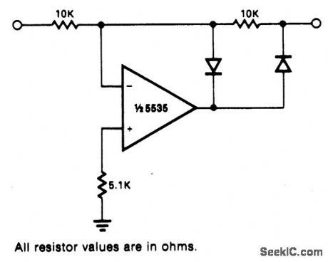
Circuit Notes
This circuit provides for accurate half wave rectification of the incoming signal. For positive signals, the gain is 0; for negative signals, the gain is -1. By reversing both di-odes, the polarity can be inverted. This circuit provides an accurate output, but the output impedance differs for the two input polarities and buffering may be needed. The output must slew through two diode drops when the input polarity reverses. The NE5535 device will work up to 10 kHz with less ttan 5% distortion. (View)
View full Circuit Diagram | Comments | Reading(0)
| Pages:7/19 12345678910111213141516171819 |
Circuit Categories
power supply circuit
Amplifier Circuit
Basic Circuit
LED and Light Circuit
Sensor Circuit
Signal Processing
Electrical Equipment Circuit
Control Circuit
Remote Control Circuit
A/D-D/A Converter Circuit
Audio Circuit
Measuring and Test Circuit
Communication Circuit
Computer-Related Circuit
555 Circuit
Automotive Circuit
Repairing Circuit