
Digital Circuit
Index 8
LADDER_ATTENUATOR
Published:2009/6/25 22:51:00 Author:May
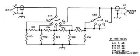
Inserted in series with receiving antenna to provide 5 steps of attenuation for comparing performance of anten-nas or preamps. Resistors are 1/4-W composition with 5% tolerance.-D. DeMaw, What Does My S-Meter Tell Me?, QST, June 1977, p 40-42. (View)
View full Circuit Diagram | Comments | Reading(0)
DELAYED_BRAKE
Published:2009/6/25 22:48:00 Author:May
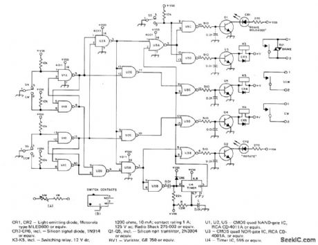
Protects antenna rotator on high tower from damage by delaying brake ac-tion automatically after rotation and by disa-bling direction-selector switches so antenna system coasts to stop before rotation can begin in other direction. For about 3.s delay in timer U4, use 2.2 megohms for R and 1μF for C instead of values shown. RV1 is commonly listed as V150LA20A by GE.S3-S5 are original brake release and direction switches in CDE Hamllrotor system,Article coners construction and installation, including modifications needed Incontrol unit.-A.B,White,A Delayed Brake Release for the Ham-ll,QST, Aug.1977、p14- 16 (View)
View full Circuit Diagram | Comments | Reading(0)
TELEMETRY_DEMODULATOR
Published:2009/6/25 22:44:00 Author:May
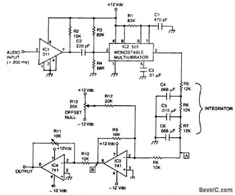
Circuit NotesThe circuit recovers an FM audio signal that varies from less than 1 kHz to about 10 kΗz (View)
View full Circuit Diagram | Comments | Reading(729)
10_MHz_WITH_30_dB_GAIN
Published:2009/6/25 22:42:00 Author:May
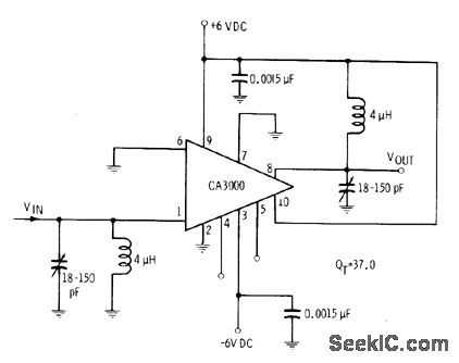
CA3000 IC is operated as RF amplifier with single-ended inputand output, With appropriate tuned circuits, amplifier performs well up to 30MHz,-E.M.Noll,″Linear IC Principles,Experiments, and Projects、″Howard W.Sams.Indianapolis、IN,1974、p91-92 (View)
View full Circuit Diagram | Comments | Reading(823)
TELEPHONE_LINE_POWERED_REPERTORY_DIALER
Published:2009/6/25 22:26:00 Author:May
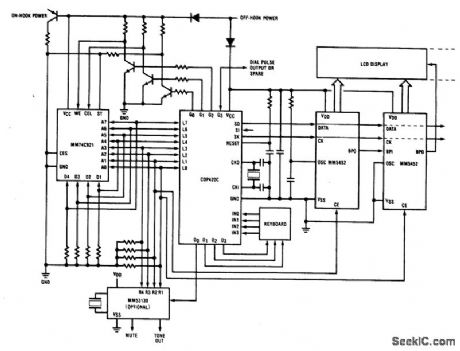
Repertory dialer phone has a library of fifteen frequently used numbers,(plus the last number dialed)stored In a standard CMOS RAM,A pushbutton keyboardenables telephone numbers to be keyed in and dialed out directly or a telephone number to be stored in the RAM and dialed automatically. (View)
View full Circuit Diagram | Comments | Reading(724)
70_dB_VOLTAGECONTROLLED_GAIN
Published:2009/6/25 22:24:00 Author:May
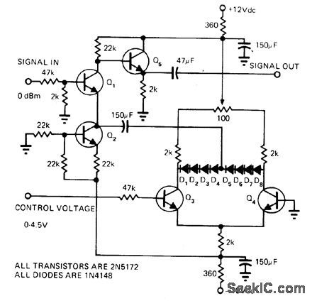
Amplifier Q1 uses current source Q2 as emitter resistor to provide correct current bias for class A operation. Coupling through 150-μF capacitor to silicon diode string D1-D8 provides variable re-sistance needed to achieve variable gain. Sim-ple differential amplifier Q3-Q4 adjusts forward bias of diodes to change their forward resis-tanco. Increasing positive control voltage from 0 to 4.5 V changes voltage gain from -74 dBm to about -4 dBm with respect to 0-dBm input signaL-N.A Steiner, Voltage-Controlled Am-plifier Covers 70 dB Range, EDN Magazine, March 5, 1975, p 72 and 74. (View)
View full Circuit Diagram | Comments | Reading(697)
40_265_MHz_VMOS
Published:2009/6/25 22:21:00 Author:May
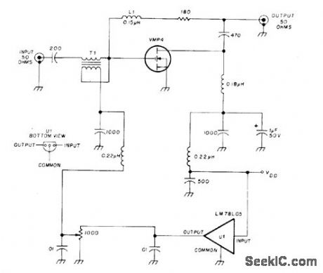
Wideband power amplifier using Siliconix Mospower FET in negative-feed-back circuit has flat gain within 0.5 dB over entire operational range of 40 to 265 MHz. Use 6 to 8 turns of No.30 on 1/2-W 1-megohm resistor for L1 (not commercially molded choke). T1 is 4 turns No.22 twisted- pair on Indiana General F625-902 toroid core. Avoid static charges until transistor is soldered into circuit.-E. Oxner, Mospower FET as a Broadband Amplifier, Ham Radlio, Dec.1976, p 32-35. (View)
View full Circuit Diagram | Comments | Reading(699)
TELEPHONE_CONTROLLED_TAPE_STARTER_TCTS
Published:2009/6/25 22:18:00 Author:May
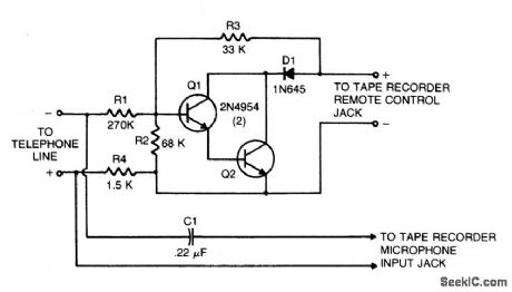
This circuit converts a tape recorder into a completely automatic telephone conversation recording instrument that needs no external power source. Voltage at the switch terminals of tape recorder applied to a pair of Darlington-connected transistors, Q1 and Q2, will turn on and start the tape recorder. To turn the transistors off, and thereby stop the machine, apply a negative voltage to the base of Q1 from the phone line. When the telephone receiver is on the hook, there is typically about 50 volts dc across the phone divided across R1, R2, and R4 in such a way that the base of Q1 is sufficiently negative to keep the tape recorder off. When the phone's receiver is picked up, the voltage on the telephone line drops to about 5 volts, which leaves insufficient negative vol-tage on the base of Q1 to keep it cut off, so the tape recorder starts and begins to record. (View)
View full Circuit Diagram | Comments | Reading(797)
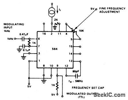
VHF_MODULATOR
Published:2009/6/25 22:17:00 Author:May
View full Circuit Diagram | Comments | Reading(0)
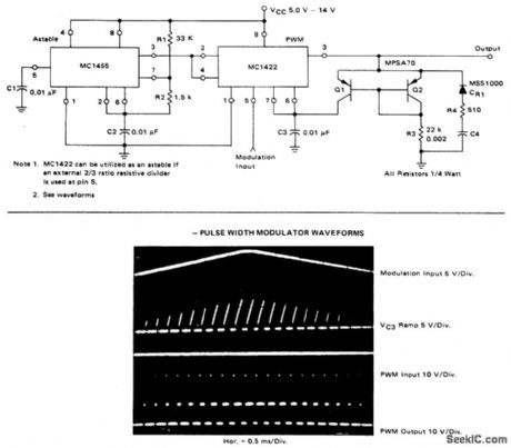
4PULSE_WIDTH_MODULATOR
Published:2009/6/25 22:16:00 Author:May
View full Circuit Diagram | Comments | Reading(716)
3PULSE_WIDTH_MODULATOR
Published:2009/6/25 22:14:00 Author:May
View full Circuit Diagram | Comments | Reading(635)
TONE_DIAL_SEQUENCE_DECODER
Published:2009/6/25 22:14:00 Author:May
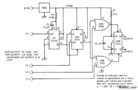
The circuit takes active low inputs from a Touch Tone decoder and reacts to a proper sequence of digits. The proper sequence is determined by which Touch Tone digits the user connects to the sequence decoder inputs TT1, TT2, TT3, and TT4. (View)
View full Circuit Diagram | Comments | Reading(1000)
TONE_DIAL_ENCODER
Published:2009/6/25 22:13:00 Author:May
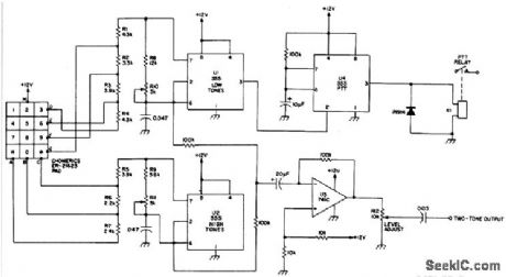
Tone dial encoder with automatic PTT control uses the 555 timers. (View)
View full Circuit Diagram | Comments | Reading(801)
AM_MODULATOR
Published:2009/6/25 22:11:00 Author:May
View full Circuit Diagram | Comments | Reading(852)
2PULSE_WIDTH_MODULATOR
Published:2009/6/25 22:10:00 Author:May
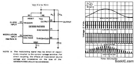
The monostable circuit is triggered by a continuous input pulse train and the threshold voltage is modulated by a control signal. The resultant effect is a modulation of the output pulse width, as shown. A sine-wave modulation signal is illustrated, but any wave-shape could be used. (View)
View full Circuit Diagram | Comments | Reading(896)
MODULATOR_
Published:2009/6/25 22:09:00 Author:May
View full Circuit Diagram | Comments | Reading(731)
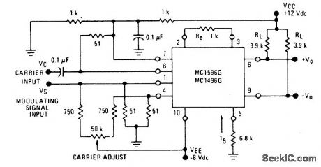
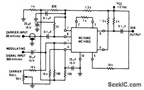
BALANCED_MODULATOR_(+12_Vdc_SINGLE_SUPPLY)
Published:2009/6/25 22:09:00 Author:May
View full Circuit Diagram | Comments | Reading(612)
VIDEO_MODULATOR_
Published:2009/6/25 22:07:00 Author:May

View full Circuit Diagram | Comments | Reading(1557)
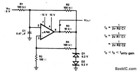
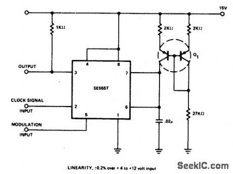
LINEAR_PULSE_WIDTH_MODULATOR
Published:2009/6/25 22:07:00 Author:May
View full Circuit Diagram | Comments | Reading(763)
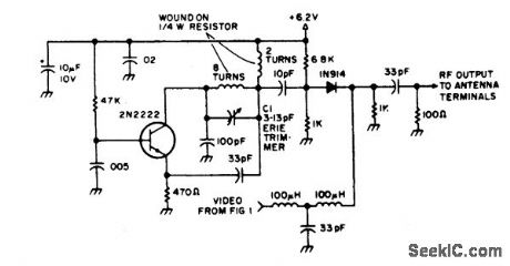
RE_MODULATOR
Published:2009/6/25 22:05:00 Author:May
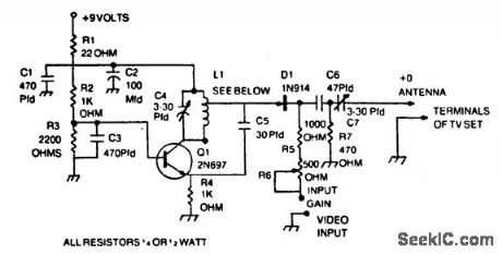
Capacitors C1, C3, C5, and C6 should be dipped mica. C4 and C7 are compression or piston trimmer types. R6 is PC-board mount trimpot. L1 is 6 tums of No.14 enameled wire, 3/8 inch I.D. by 3/4 inch long, tapped at 1 turn from top. (View)
View full Circuit Diagram | Comments | Reading(756)
| Pages:8/19 12345678910111213141516171819 |
Circuit Categories
power supply circuit
Amplifier Circuit
Basic Circuit
LED and Light Circuit
Sensor Circuit
Signal Processing
Electrical Equipment Circuit
Control Circuit
Remote Control Circuit
A/D-D/A Converter Circuit
Audio Circuit
Measuring and Test Circuit
Communication Circuit
Computer-Related Circuit
555 Circuit
Automotive Circuit
Repairing Circuit