
Digital Circuit
Index
USB RDS Coder Board using ATmega32
Published:2012/11/15 20:59:00 Author:muriel | Keyword: USB , RDS, Coder Board , ATmega32

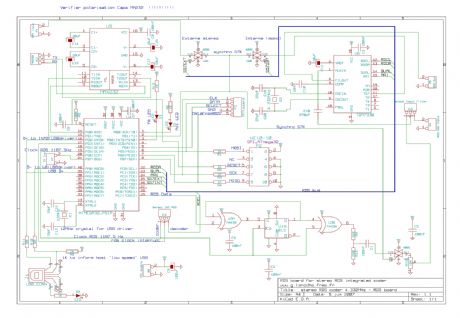
This board is a RDS coder using an ATMEL AVR ATmega32. This board can be controled by a RS232 link, USB interface or SPI. TA data is displayed wiyth a LED and can be controled by : - Hardware input - RS232 - USB - SPI (not yet implemented) (View)
View full Circuit Diagram | Comments | Reading(3226)
Electronic Mail Box circuit
Published:2012/10/10 1:47:00 Author:muriel | Keyword: Electronic Mail Box
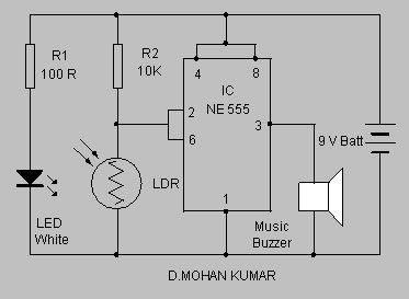
This Electronic Mail Box circuit generates music intimating the arrival of mail……..The circuit uses a high bright White LED and an LDR to detect the arrival of mail in the box. IC NE 555 is designed as a Schmitt trigger by shorting its trigger pin 2 and threshold pin 6. When the light from the LED illuminates the face of LDR, it conducts taking the pin 6 of IC low. Output pin 3 then remains low inhibiting the buzzer.When a mail falls between the LED and LDR, light from LED will be blocked and the LDR becomes non conducting. This makes the threshold pin of IC high and its output goes high. The high output makes buzzer active and music will be heard. The music stops only when the letter is removed from the box. Keep LED and LDR at the opposite sides of the box. (View)
View full Circuit Diagram | Comments | Reading(1488)
DIY Digital Thermometer Circuit
Published:2012/9/19 21:38:00 Author:Ecco | Keyword: DIY, Digital Thermometer
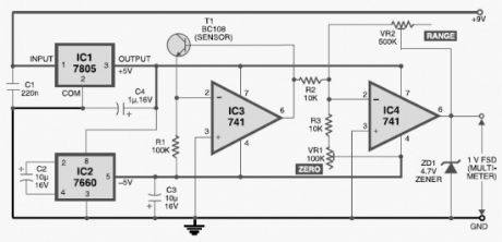
This diy digital thermometer circuit can measure temperatures up to 150°C with an accuracy of ±1°C. The temperature is read on a 1V full scale-deflection (FSD) moving-coil voltmeter or digital voltmeter.How the digital thermometer worksOperational amplifier IC 741 (IC3) provides a constant flow of current through the base-emitter junction of npn transistor BC108 (T1). The voltage across the base-emitter junction of the transistor is proportional to its temperature. The transistor used this way makes a low-cost sensor. You can use silicon diode instead of transistor.The small variation in voltage across the base-emitter junction is amplified by second operational amplifier (IC4), before the temperature is displayed on the meter. Preset VR1 is used to set the zero-reading on the meter and preset VR2 is used to set the range of temperature measurement.Operational amplifiers IC3 and IC4 operate off regulated ±5V power supply, which is derived from 3-terminal positive voltage regulator IC 7805 (IC1) and negative low-dropout regulator IC 7660 (IC2). The entire circuit works off a 9V battery.Assemble the circuit on a general-purpose PCB and enclose in a small plastic box. Calibrate the thermometer using presets VR1 and VR2. After calibration, keep the box in the vicinity of the object whose temperature isto be measured.
Sent by Mihail Dorutz, CH. Thanks a lot!
Digital Thermometer Circuit Schematic
5 Responses to “DIY Digital Thermometer Circuit”
Source: electroschematic.com
(View)
View full Circuit Diagram | Comments | Reading(1604)
Digital electric clock circuit diagram
Published:2011/8/30 1:56:00 Author:Jessie | Keyword: Digital electric clock
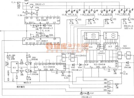
As shown in figure, digital electric clock circuituses electronic horologe special integrated circuit KD482FCas seconds time-base signal. Through the digital circuit multi-stage separate frequency, it formsminute and hour to output. The minute isdisplayed byLED digital tube; While hour display is the analog dial structure of mechanical pointer clock,and itis displayed by light-emitting diodes in the dial. It's timing accurately, novelly, so it is very suitable for amateur toimitate. The circuit is composedof thesecond time base signal form circuit, minute time formation-display circuit and the hour formation-display circuit. (View)
View full Circuit Diagram | Comments | Reading(1725)
74 series digital circuit 74HC564 and other eight D flip-flop (three-state, opposite phase)
Published:2011/11/11 0:43:00 Author:May | Keyword: , eight D flip-flop, three-state, opposite phase
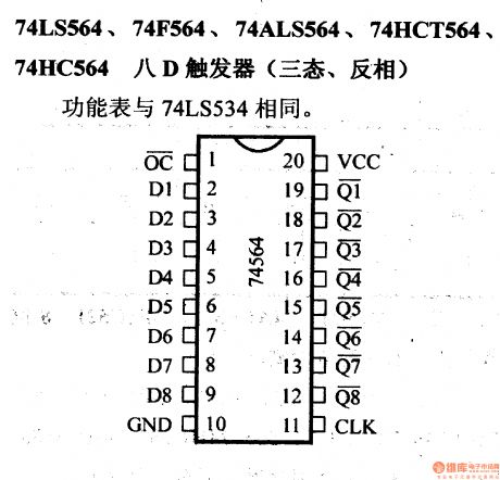
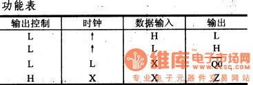
Its function table is the same with 74LS534. (View)
View full Circuit Diagram | Comments | Reading(997)
74 series digital circuit 74LS563 eight D latch (three-state, opposite phase)
Published:2011/11/11 0:43:00 Author:May | Keyword: digital, eight D latch, three-state, opposite phase
Its function table is the same with 74LS533. (View)
View full Circuit Diagram | Comments | Reading(996)
74 Series digital circuit 74LS540/541 and other eight buffer/bus driver (three-state)
Published:2011/11/11 0:42:00 Author:May | Keyword: digital, eight buffer, bus driver, three-state
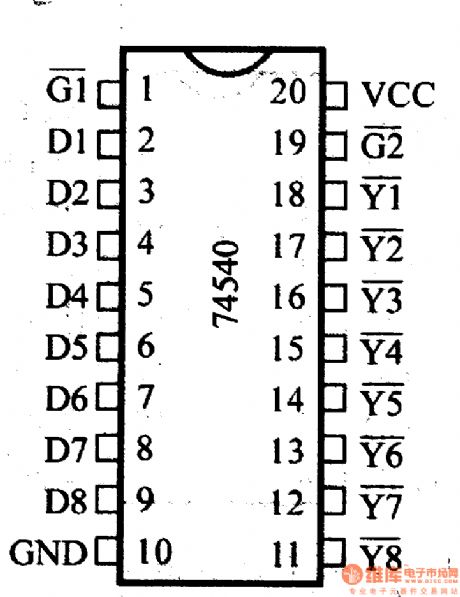
When either G1 or G2 (or both of them ) is high , all outputs are in high impedance ; when G1 and G2 are in low level, the output is valid. 540 is the inverting output. 541 is the same-phase output.
(View)
View full Circuit Diagram | Comments | Reading(1892)
74 series digital circuit 74LS537 BCD-decimal decoder (Tri-State)
Published:2011/11/11 0:37:00 Author:May | Keyword: 74 series, digital, BCD-decimal decoder, Tri-State
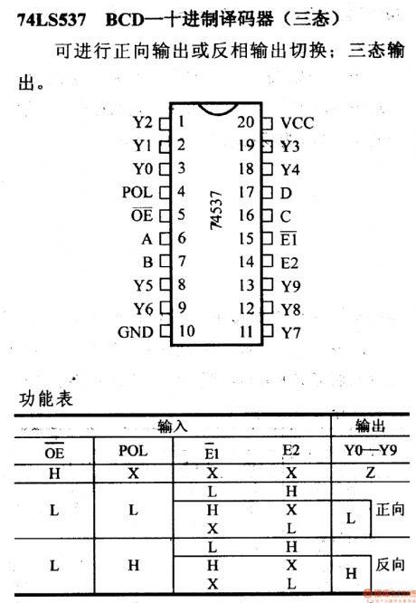
It can do forward output or inverted output switching; It has tri-state output. (View)
View full Circuit Diagram | Comments | Reading(2174)
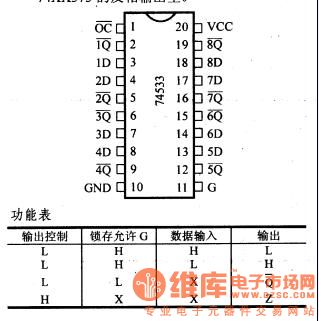
74 series of digital circuit 74LS534 octal D latch (tri-State, inverting)
Published:2011/11/11 0:33:00 Author:May | Keyword: 74 series, digital, eight D latch, Tri-State, inverting
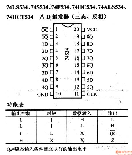
Q0 = the output level before establishing steady-state input conditions (View)
View full Circuit Diagram | Comments | Reading(1478)
74 series digital circuit 74LS533 octal D latch (Tri-State, inverting)
Published:2011/11/11 0:29:00 Author:May | Keyword: 74 series, digital, octal D latch, Tri-State, inverting
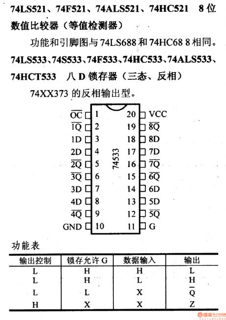
Function and pin diagram are the same with 74LS688 and 74HC688. 74LS533, 74S533, 74F533.74HC533, 74ALS533, 74HCT533 octal D- Latch ( Tri-State , inverting ). 74XX373 is inverting output type. (View)
View full Circuit Diagram | Comments | Reading(1977)
Digital hygrometer
Published:2011/11/7 19:12:00 Author:Ecco | Keyword: Digital hygrometer
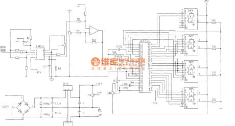
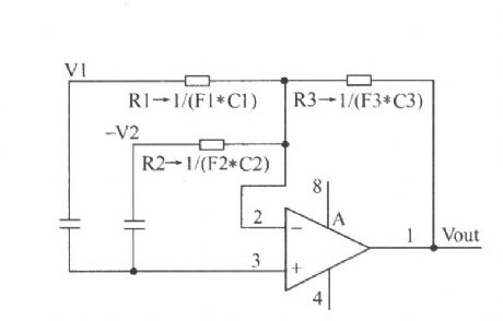
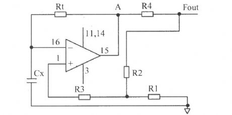
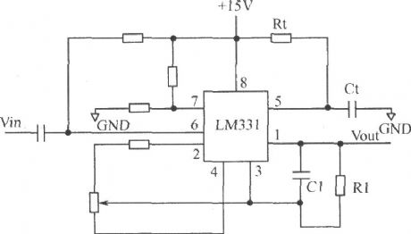
Digital hygrometer mainly consists of the following circuits :(1 ) humidity / voltage conversion circuit; (2 ) humidity / frequency converter circuit; (3 )the circuit composed of LM331.
(View)
View full Circuit Diagram | Comments | Reading(2399)
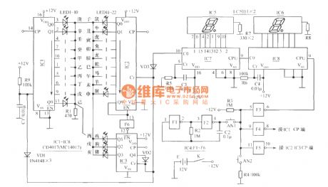
Digital Lunar, Zodiac projection device circuit
Published:2011/11/7 20:37:00 Author:Ecco | Keyword: Digital Lunar, Zodiac projection device
View full Circuit Diagram | Comments | Reading(869)
Digital displaying photoelectric counter circuit diagram
Published:2011/9/26 21:50:00 Author:Rebekka | Keyword: Digital displaying , photoelectric counter
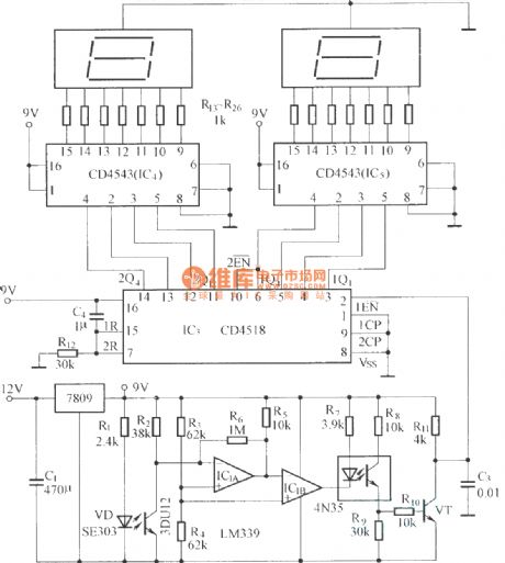
The circuit has optical input circuit (VD, 3DU12), pulse forming circuit (IC1A, IC1B form the voltage comparator; optical coupler; transistor switching circuit) and counting and display circuit. (View)
View full Circuit Diagram | Comments | Reading(2758)
Digital Potentiometers X9511 circuit diagram
Published:2011/9/16 0:50:00 Author:Rebekka | Keyword: Digital Potentiometers
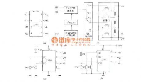
X9511 is a of non-volatile Digital Potentiometer with digital integrated circuit manufacturing process. Its internal binary counter is composed of five binary counter, five-bit rewritten read-only memory (that E2PROM), storage and clear control circuit, thirty-two selected one decoder circuit, transmission gate and resistor arrays and other components. Pin and functionare shown as above. (View)
View full Circuit Diagram | Comments | Reading(1554)
Practical Technology Circuit Diagram for Digital Integrated Circuit
Published:2011/9/13 0:11:00 Author:Zoey | Keyword: Practical Technology, Digital, Integrated Circuit
1.Time fordata setup and maintainmentDigital Circuit mainly refers to synchronouscircuits , which means by using a clock, part of the circuit or all circuits can worksynchronously.synchronouscircuits usually adoptD trigger or J-Ktrigger tolatch the data. Using these triggers, we should pay attention to the latched signal and clock timing, if thereis anyproblem, it will cause circuit malfunction. Figure a, b, c refer to the time for data setup ts and maintainment th. Trigger D uses the clock edge to read the data input and output. Before the ascending edge appears, the data should be setup. This time margin is ts. Afer the ascending edge appears, the data needs to be maintained for some time, this time margin is th.The higher IC's working speed, the shorter time is required.
In practical, if ts and th are not long enough, the trigger will be in a multi-valued state, that is, in ameta-stable state,which means theinput processwillhave along delay time, the level will not be determined, and the trigger will havemalfunction.
(View)
View full Circuit Diagram | Comments | Reading(695)
74 series digital circuit of 74LS398/399 4-bit 2-to-1 data selector
Published:2011/8/11 3:20:00 Author:Lucas | Keyword: 74 series , digital circuit, 4-bit , 2-to-1 data selector
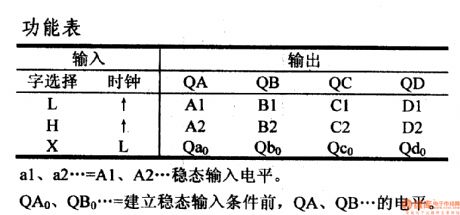
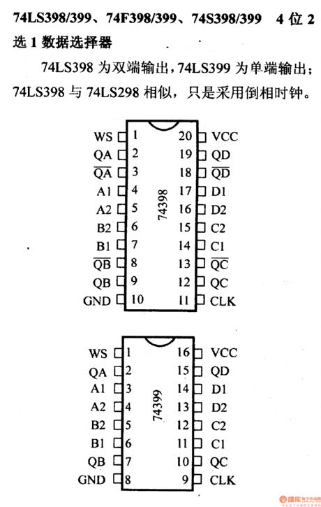
a1, a2 ...= A1, A2 ... steady input level. QA0, QB0 ...= QA, QB ... level before the establishment of steady-state input conditions.74LS398/ 74LS399, 74F398/ 74LS399, 74S398/ 74LS399 4-bit 2-to-1 data selector 74LS398 has dual-ended output, and 74LS399 has single-ended output; 74LS398 and 74LS298 are similar, and they use the reverse phase clock.
(View)
View full Circuit Diagram | Comments | Reading(1161)
74 Series digital circuit of 74293,74LS293 4-bit binary counter
Published:2011/8/12 2:22:00 Author:Lucas | Keyword: 74 Series , digital circuit, 4-bit binary counter
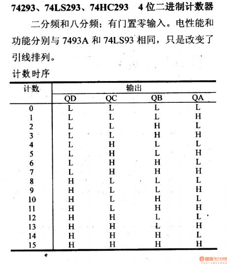
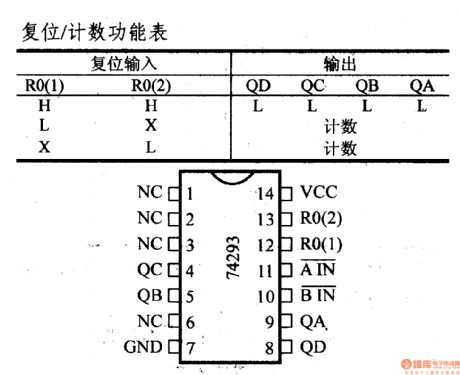
Ithas zero gate input. Electrical performance and functionality are the same with the 7493A and 74LS93. It just changes the lead arrangement.
(View)
View full Circuit Diagram | Comments | Reading(4272)
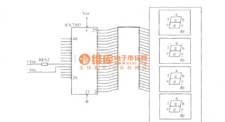
Digital display thermometer circuit
Published:2011/8/26 3:25:00 Author:Jessie | Keyword: Digital display, thermometer
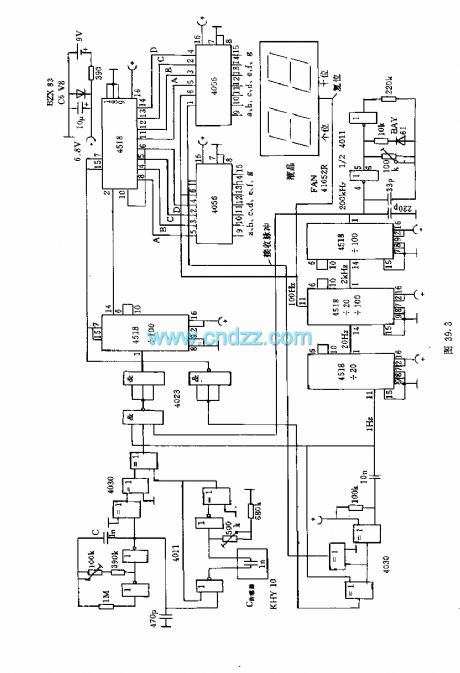
Thecapacitive moisture sensor KHY10 canform the humidity meter whichis displayed by double-digit percentages of LCD display. The pulse width of single state trigger produced by 1kHz quote swings device depends on the sensor elements' capacitance. In zero humidity, single state trigger's pulse width isequal to oscillating wave's half cycle. These two pulses are added to the XOR gate to form the difference pulse signal, and according to the difference between the pulse width, the 200KHz signal is added the AND gate. If there is differential pulse, the output is only pulses.
(View)
View full Circuit Diagram | Comments | Reading(1499)
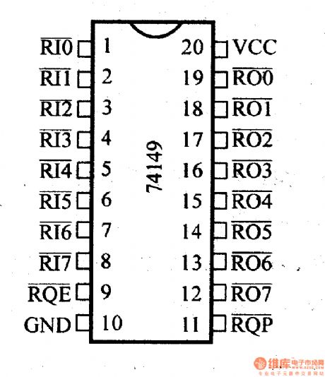
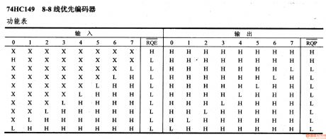
74 Series digital circuit of 74HC149 8-8 line priority encoder
Published:2011/8/1 20:54:00 Author:Lucas | Keyword: 74 Series , digital circuit, 8-8 line priority encoder
View full Circuit Diagram | Comments | Reading(1965)
74 Series digital circuit of 74142 BCD counter / 4-bit latch / BCD decoder / driver
Published:2011/7/25 3:14:00 Author:Lucas | Keyword: 74 Series, digital circuit , BCD counter, 4-bit latch, BCD decoder, BCD driver
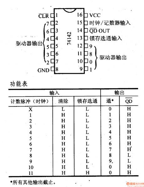
All other outputs are off.
It contains a BCD counter, a 4-bit latch and a decoder, Nixie tube driver; the counter accepts input clock frequency which is up to 20MHZ; driver tube has the same input with 74141.
(View)
View full Circuit Diagram | Comments | Reading(3500)
| Pages:1/19 12345678910111213141516171819 |
Circuit Categories
power supply circuit
Amplifier Circuit
Basic Circuit
LED and Light Circuit
Sensor Circuit
Signal Processing
Electrical Equipment Circuit
Control Circuit
Remote Control Circuit
A/D-D/A Converter Circuit
Audio Circuit
Measuring and Test Circuit
Communication Circuit
Computer-Related Circuit
555 Circuit
Automotive Circuit
Repairing Circuit