
Digital Circuit
Index 16
LIGHT_WAVE_VOICE_COMMUNICATION_RECEIVER
Published:2009/6/16 23:54:00 Author:May
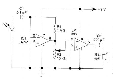
This light-wave receiver consists of a 741 op-erated as a preamplifier and an LM386 operated as a power amplifier. Potentiometer R2 is the gain control. Various kinds of detectors can be used as the front end of the receiver. Phototransistors are very sensitive, but they do not work well in the presence of too much ambient light. A 100-kQ se-ries resistor is required if you use a phototransis-tor. Solar cells, photodiodes, and LEDs of the same semiconductor as the transmitter all work well in this circuit. (View)
View full Circuit Diagram | Comments | Reading(982)
FM_LIGHT_BEAM_RECEIVER
Published:2009/6/16 23:51:00 Author:May
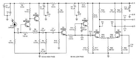
This receiver will pick up IR or light beams that are frequency modulated on a 50-kHz carrier Q2/Q1/Q3/Q4 from an active filter and amplifier and differential amp Q5/Q6 provide more gain. (View)
View full Circuit Diagram | Comments | Reading(802)
POWER_MOSFET_INVERTER
Published:2009/6/16 23:29:00 Author:May
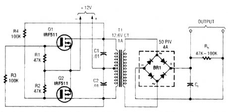
T1 is a suitable transformer for the voltage desired, with a 12.6-V CT winding. (View)
View full Circuit Diagram | Comments | Reading(1)
dc_to_ac_INVERTER
Published:2009/6/16 23:28:00 Author:May
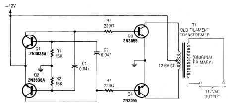
A multivibrator circuit drives a pair of 2N3055 power transistors transformer with a 120-V primary. (View)
View full Circuit Diagram | Comments | Reading(5808)
DIGITAL_INVERTER
Published:2009/6/16 23:27:00 Author:May
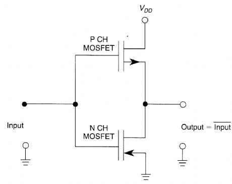
A CMOS digital inverter is formed by con-necting two MOSFETS, as shown. (View)
View full Circuit Diagram | Comments | Reading(850)
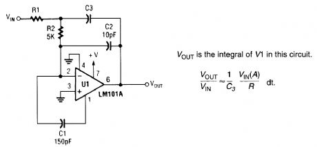
FAST_INTEGRATOR
Published:2009/6/16 22:54:00 Author:May
View full Circuit Diagram | Comments | Reading(1)
AND_GATE
Published:2009/6/16 21:46:00 Author:May
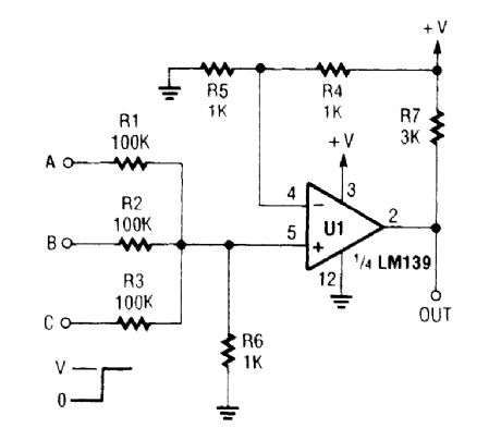
A left-over section of a quad op amp can be used to save cost and eliminate an extra logic chip for this AND gate. (View)
View full Circuit Diagram | Comments | Reading(0)
2_MHz_FREQUENCY_COUNTER
Published:2009/6/15 20:48:00 Author:May
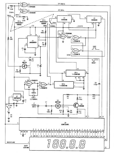

This is a schematic and block diagram of a 2-MHz frequency counter. It uses and LSI counter/display driver, LCD readout, and a,few logic chips for timebase and timing pulse circuitry. Q2 and Q3 form a signal (input) amplifier.The circuit contains a crystal oscillator built around U3-c and XTALl, which provides the pri-mary timing-reference signal. That signal is then divided twice to provide two additional timing ref-erences, giving the circuitry three selectable timing references. The ICM7224IPL is an integrated circuit that consists of the counter and display driver to drive the LCD-004 display. (View)
View full Circuit Diagram | Comments | Reading(3576)
74 series of digital circuit, 74143,74144 4-bit counter / latch, seven-segment LED / lamp driver
Published:2011/7/24 4:32:00 Author:Lucas | Keyword: 74 series , digital circuit, 4-bit counter , 4-bit latch, seven-segment LED , lamp driver
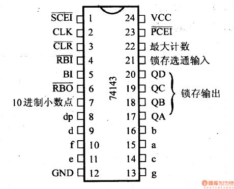
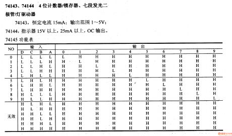
The constant current of 74143 is 15mA, and the output range is 1-5V; the indicating voltage of 74144 is above 15V, and current is more than 25mA with OC output. 74145 functional table
(View)
View full Circuit Diagram | Comments | Reading(2338)
74 series digital circuit of 74LS424 two-phase clock generator/driver
Published:2011/7/21 3:24:00 Author:Lucas | Keyword: 74 series , digital circuit , two-phase clock generator, two-phase clock driver
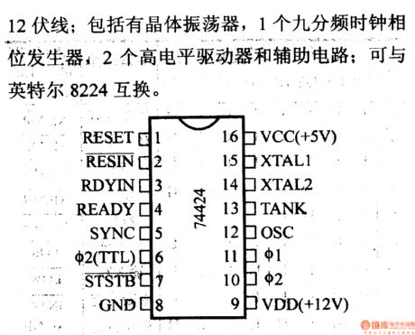
It is used to drive all 8080A microprocessors and 12V lines; it includes crystal oscillator, a nine-frequency clock phase generator, 2 high-level driver and auxiliary circuit; it can exchange with the Intel 8224.
(View)
View full Circuit Diagram | Comments | Reading(1124)
MC68HCO5C4-Communication single chip micro computer integrated circuit
Published:2011/7/16 2:45:00 Author:leo | Keyword: single chip micro computer, 24 dual-orientation
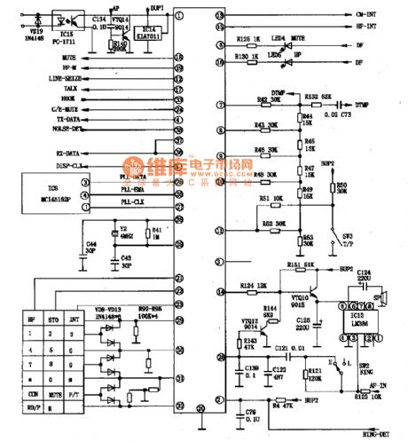
MC68HCO5C4 is a kind of single chip micro computer which is widely used in wireless telephone and always be used as thecontrol chip of main engine.1. Inner circuit diagramMC68HCO5C4 adopts CMOS and has 16 bit input snapping and output comparing self-timer system(IC/OC), constant connecting periphery interface SPI, constant connecting communication interface SCI, 24 dual-orientation input and output line, that is AO-PA7, PBO-PB7, PCO-PC7.
2.MC68HCO5C4 can finish 16 bit snapping and output comparing self-timer system. It can also use output comparing function to generate dual-sound multi-frequency DTMF signals, code data signals, impulse dialing signals, gentle tone and so on. (View)
View full Circuit Diagram | Comments | Reading(749)
Digital velocity detection circuit
Published:2011/5/13 3:33:00 Author:Nicole | Keyword: digital velocity detection
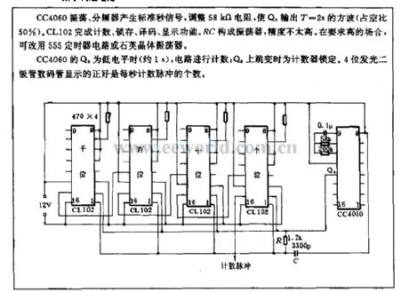
CC4060 oscillation, frequency divider produces standard second signal, to adjust 58kΩ resistance, to make Q9 outputs T=2s square wave(duty cycle is 50%). CL102 completes counting, latch, decoding, display function. RC forms oscillator, but the precision is not high. In demanding occasion, we can use 555 timer circuit or quartz crystal oscillator.
When Q9 of CC4060 is low level(about 1s), the circuit starts to count; when Q9 isjumping, the timer is latched. 4 bits LED displays the number of count pulse per second. (View)
View full Circuit Diagram | Comments | Reading(805)
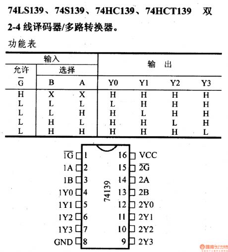
74 series digital circuit of 74LS139 and 74S139 2-4 line decoder/multi-channel converter
Published:2011/5/17 3:18:00 Author:Ecco | Keyword: digital circuit , 2-4 line decoder, multi-channel converter
View full Circuit Diagram | Comments | Reading(2887)
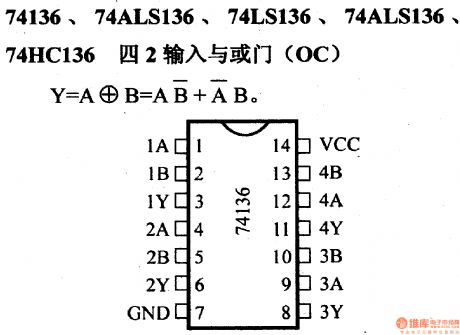
74 series digital circuit of 74136 and 74ALS136 four 2 input and nor gate(OC)
Published:2011/5/17 3:21:00 Author:Ecco | Keyword: digital circuit , four 2 input, nor gate
View full Circuit Diagram | Comments | Reading(1389)
74 series digital circuit of 7473 and 74H73 input J - K master-slave flip-flop
Published:2011/5/17 3:22:00 Author:Ecco | Keyword: digital circuit, input J - K, master-slave flip-flop
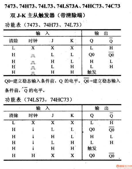
7473, 74H73,74L73, 74LS73A, 74HC73, 73C73double J - K master-slave flip-flop(with remove terminal)
The level of Qo is equal to Q before eatablishing steadystate input. (View)
View full Circuit Diagram | Comments | Reading(1996)
74 series digital circuit 74LS447, BCD seven sections decoder/driver
Published:2011/6/26 21:12:00 Author:Nicole | Keyword: 74 series, digital circuit, decoder, driver
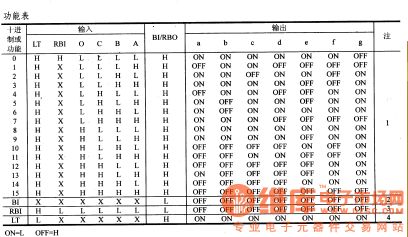
74LS447, BCD-seven sections decoder/driver
It is 74LS447's voltage form, the withstand voltage is 7V; the collector open circuit directly drives indicator; it has a test light; front/back edge cuts off 0 ; the brightness of indicator can be adjusted, the pin and functional table are the same as 74LS447.
(View)
View full Circuit Diagram | Comments | Reading(1149)
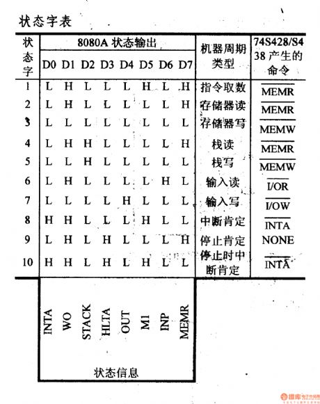
74 series digital circuit 74S428 system controller and bus driver
Published:2011/6/26 21:52:00 Author:Nicole | Keyword: 74 series, digital circuit, system controller, bus driver
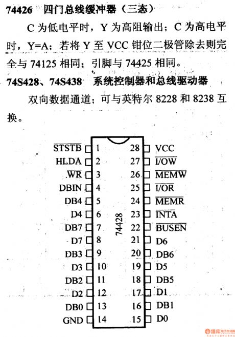
74426 four gates bus buffer(there states)
C is low level, Y is high resistance output; when C is high level, Y=A, if the diodes of Y to VCC clamped are removed, then it is the same as 74125 absolutely; the pin is the same as 74425.
74S428, 74S438 system controller and bus driver
two-way data channel: it can be exchanged with Intel 8228 and 8238.
(View)
View full Circuit Diagram | Comments | Reading(1047)
MC68HC5Pl-Communication single-chip microcomputer integrated circuit diagram
Published:2011/7/10 2:44:00 Author:leo | Keyword: Communication, single-chip
MC68HC5PI is a kind of communication single-chip microcomputer integrated circuit made by Motorola which can be applied in wireless telephone and is used as control chip in cell phone.
1.Function Feature:The integrated circuit MC68HC5PI is a type of chip which uses CMOSCPU as the core chip and has 16-bit input capturing and output comparing timers, serial peripheral interface, serial communication interface, 416OKB ROM, 24 double action I/O and can carry out the function of generating dual-tone multifrequency signals, coding data signals and pulsing dialing signals that that can be used to memory code information and so on.
2.Pin Function and dataMC68HC5PI is always used together with MC68HCO5C4(MC68HCO54P) as a microcomputer of the cell phone. All pins function and data of the integrated circuit are shown in the picture bellow. (View)
View full Circuit Diagram | Comments | Reading(570)
TMP87CS38N-Single chip microcomputer integrated circuit
Published:2011/7/3 3:08:00 Author:leo | Keyword: TMP87CS38N-Single chip microcomputer integrated circuit

TMP87CS38N is a kind of single chip microcomputer integrated circuit made by Toshiba in Japan. It is especially used in the microcontroller chip of changhong projection color television 51PT28A.
1.Function features:The integrated circuit TMP87CS38N, memory AT25C08, IR-Control emitter K8G, IR-Control signal receiver HSO038 as well as interface circuits form complete color television remote control circuit. Except the various control functions, it has +148 V, +18 V and -18 V power supply over current test and protection function.
2.Pin functions and related data:The integrated circuit TMP87CS38N adopts 42 pin dual line package. All information is shown in the picture. (View)
View full Circuit Diagram | Comments | Reading(783)
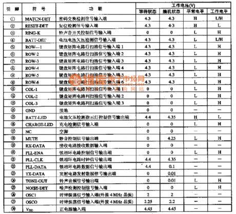
VCT3803-O1A-Super TV single chip integrated circuit
Published:2011/6/17 7:44:00 Author:leo | Keyword: VCT3803-O1A-Super TV single chip integrated circuit, TDA4472, MSP3463G
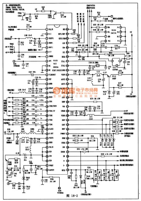
VCT3803-O1A is a kind of super TV single chip integrated circuit used in German which is widely used in big screen color television.1. Function Features:VCT3803-O1A contains micro processor, TV/AV converting circuit, brightness signal processing circuit, color signal demodulating circuit, BGR square circuit, BGR signal selecting switch circuit and so on.2.Pin Functions and data:VCT3803-O1A is used in P2960S KangJia series color television and its pin functions and data are shown in the picture. (View)
View full Circuit Diagram | Comments | Reading(1153)
| Pages:16/19 12345678910111213141516171819 |
Circuit Categories
power supply circuit
Amplifier Circuit
Basic Circuit
LED and Light Circuit
Sensor Circuit
Signal Processing
Electrical Equipment Circuit
Control Circuit
Remote Control Circuit
A/D-D/A Converter Circuit
Audio Circuit
Measuring and Test Circuit
Communication Circuit
Computer-Related Circuit
555 Circuit
Automotive Circuit
Repairing Circuit