
Circuit Diagram
Index 1112
DARLINGTON_PAIR_SERVO_AMPLIFIER
Published:2009/7/23 23:19:00 Author:Jessie
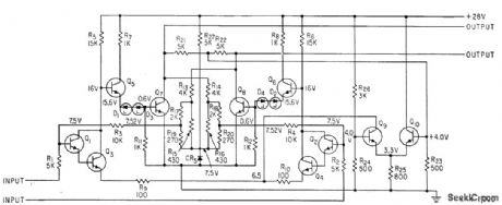
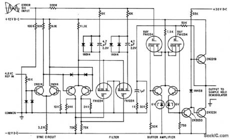
Open-loop gain of differential forward amplifier Q1 through Q8 is over 2,000 and dosed-loop gain is 200. Signal across output of common-mode feedback amplifier Q9-Q10 is differentially summed by R21-R22 to cancel a-c components, while d-c component is amplified and applied to emitters of differential-input Darlington pair.-M. W. Aarons, Putting a Servo Amplifier on a Small Silicon Wafer, Electronics, 35:52, p 33-35. (View)
View full Circuit Diagram | Comments | Reading(692)
140_W_PEP_2__to_30_MHz_amateur_radio_linear_amplifier
Published:2009/7/23 23:19:00 Author:Jessie
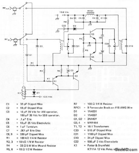
Both the parts and kits for this amplifier are available from: Commu-nications Concepts, 121 Brown St. Dayton, Ohio 45402, (513) 220-9677. Use of this amplifier is illegal for the class-D citizen band. (View)
View full Circuit Diagram | Comments | Reading(623)
PREFERRED_INTERMEDIATE_LEVEL_AMPLIFIER
Published:2009/7/23 23:19:00 Author:Jessie
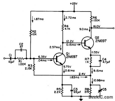
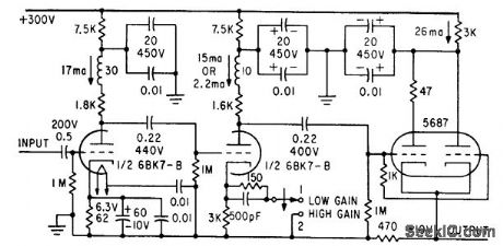
Is noninverting linear pulse voltage amplifier. May follow radar second detector. Minimum bandwidth is 3 Mc and maximum output 6 v. Signal polarity is positive input and positive output.-NBS, Handbook Preferred Circuits Navy Aeronautical Electronic Equipment, Vol. II, Semiconductor Device Circuits, PSC 19 (originally PC 219), p 19-2. (View)
View full Circuit Diagram | Comments | Reading(1051)
FINE_SERVO_REGULATOR
Published:2009/7/23 23:27:00 Author:Jessie
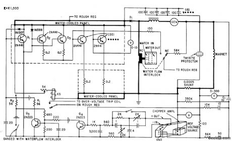
Used in double-loop servo system that holds field of Large electromagnet constant to one part in 15,000,000. Primary loop or rough regulator establishes small region over which fine regulator operates. Uses 20 paralleled transistors in output stage to regulate by dissipating some of available power.-A. M. Patlach, Precision Servo Regulator Controls High-Power Magnetic Field, Electronics, 33:45, p 66-69. (View)
View full Circuit Diagram | Comments | Reading(838)
Widest_range_V_F_converter
Published:2009/7/23 23:27:00 Author:Jessie
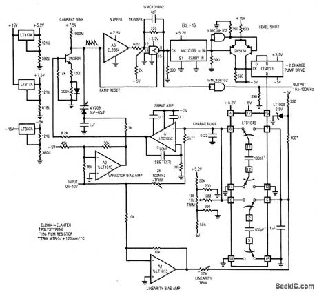
Fig. 12-7 This circuit features a 1-Hz to 100-MHz range with a linearity of 0.06%, 25 ppm/℃temperature coefficient, 50 nV/℃ (0.5 Hz/℃) zero shift, and a 0- to 10-V input range. To calibrate, apply 10.000 V and adjust the 100-MHz trim for 100.00 MHz at the output (if this is beyond counter range, the divide-by-32 signal at pin 16 of the LTC1043 should read 3.1250 MHz). Next, ground the input, install CCOMP (at the noninverting input of A1) and adjust the 1-Hz trim until the circuit oscillates at 1 Hz (use 1 μF for CCOMP). Finally, set the linearity trim for 50.000-MHz output with 5.000 V at the input. Repeat these adjustments until all three points are fixed. Linear Technology Linear Applications Handbook 1990 p AN14-2. (View)
View full Circuit Diagram | Comments | Reading(722)
THREE_INPUT_VIDEO_MIXER
Published:2009/7/23 23:27:00 Author:Jessie
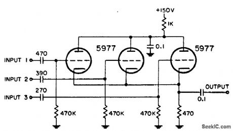
Used in radar systems for combining any three of the following: radar video, beacon, range markers, range strobe, and azimuth markers.-NBS, Handbook Preferred Circuits Navy Aeronautical Electronic Equipment, Vol. 1, Electron Tube Circuits, 1963, p N4-1. (View)
View full Circuit Diagram | Comments | Reading(626)
QUADRATURE_SUPPRESSION
Published:2009/7/23 23:26:00 Author:Jessie
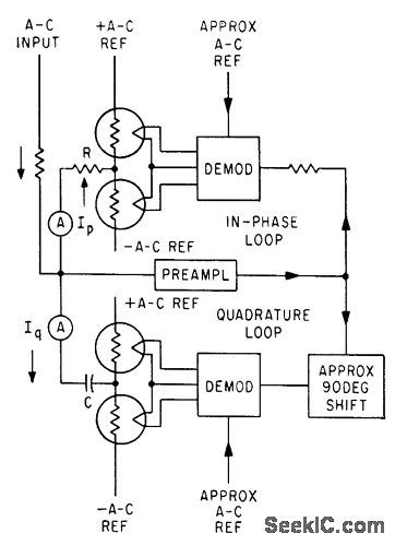
Two pairs of thermistor potentiometers balance the in-phase and quadrature components of input current, which are in phase and in quadrature with a-c reference of the same frequency, to permit displaying components simultaneously on two ac meters. Circuit and values for demodulators and preamplifier are same as for THERMISTOR CONTROL circuit.-I. C. Hutcheon, Using Thermistors as Servo Elements, Electronics, 34:5, p 52-55. (View)
View full Circuit Diagram | Comments | Reading(795)
TWO_STAGE_WIDEBAND_VIDEO_AMPLIFIER
Published:2009/7/23 23:26:00 Author:Jessie
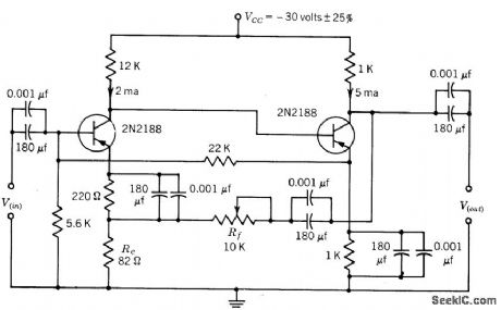
D-c feedback provides stable d-c operation for normal production spread of components and normal temperature variations. Supply voltage changes up to 25% have negligible effect on performance. Open-loop bandwidth is 1 Mc for 50 db gain, and bandwidth at 30-db closed-loop gain is 17 Mc.-Texas Instruments Inc., Transistor Circuit Design, McGraw-Hill, N.Y. 1963, p 269. (View)
View full Circuit Diagram | Comments | Reading(772)
Common_emitter_output_stage_with_voltage_gain
Published:2009/7/23 23:26:00 Author:Jessie
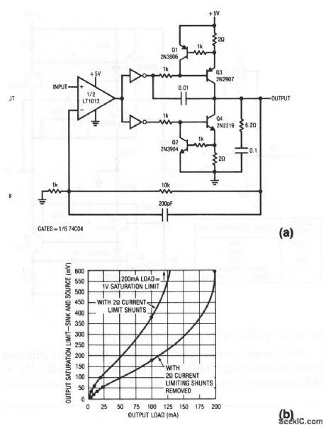
This circuit is similar to that of Fig. 1-10, except that the CMOS inverters drive bipolar transistors to reduce saturation losses, even at relatively high currents. Fig. 1-11B shows the output saturation characteristics. (View)
View full Circuit Diagram | Comments | Reading(814)
400_CPS_DRIVER
Published:2009/7/23 23:26:00 Author:Jessie
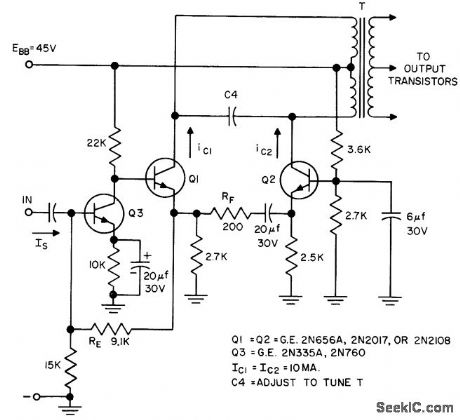
Uses modified long-tail pair to give highly stable gain. Separate emitter resistors improve bias stability. Provides push-pull operation.- Transistor Manual, Seventh Edition, General Electric Co., 1964, p 222. (View)
View full Circuit Diagram | Comments | Reading(743)
DISTANCE_MARKER_MIXER
Published:2009/7/23 23:25:00 Author:Jessie
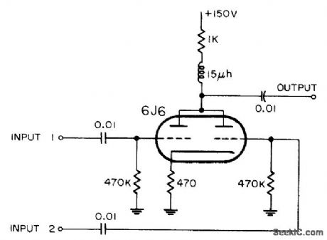
Uses compensated plate loud for triodes to combine distance markers with radar video.-NBS, Handbook Preferred Circuits Navy Aeronautical Electronic Equipment, Vol. 1, Electron Tube Circuits, 1963, p N4-3. (View)
View full Circuit Diagram | Comments | Reading(706)
3_A_positive_adjustable_current_regulator
Published:2009/7/23 23:25:00 Author:Jessie
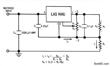
This circuit uses the LAS14AU voltage-regulator IC (Fig. 7-29) as an adjustable-current regulator. Characteristics are shown in Fig. 7-28B, 7-28C, and 7-28D. (View)
View full Circuit Diagram | Comments | Reading(730)
SINGLE_ENDED_VIDEO_PREAMP
Published:2009/7/23 23:25:00 Author:Jessie
Single-ended input from balanced mixer is achieved by terminating one arm of mixer. Bandwidth is 3 Mc. Used in microwave interferometer system.-H. L. Bunn, Determining Electron Density and Distribution in Plasmas, Electronics, 34:14, p 71-75. (View)
View full Circuit Diagram | Comments | Reading(726)
SERVO_FREQUENCY_COMPENSATION
Published:2009/7/23 23:25:00 Author:Jessie
Performs frequency compensation in servo sys tem by operating on modulation envelope of amplitude-modulated suppressed-carrier signal. Hybrid construction, replacement of linear circuits with switching circuits, and substitution of active filters for large L-C filters reduce size and weight.-F. A. Plemenos, The Packaging Revolution, Part VI: Converting to Microelectronics, Electronics, 39:4, p 103-109. (View)
View full Circuit Diagram | Comments | Reading(722)
High_speed_15_A_MOSFET_drivers
Published:2009/7/23 23:24:00 Author:Jessie
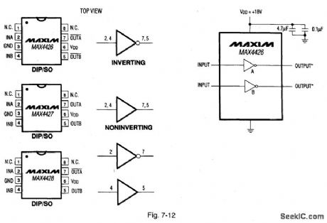
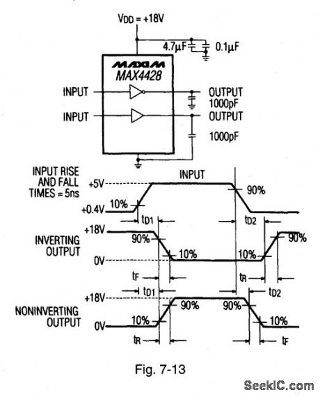
Figure 7-12 shows the basic connections for the MAX4426/27/28 drivers. Such ICs rapidly charge and discharge the gate capacitance of the largest MOSFETs to within millivolts of the supply. The typical on resistance is 4 Ω, the delay times are 10 ns for tD1 and 25 ns for tD2, the peak output current is 1.5 A, rise and fall times are typically 20 ns with 1000-pF loads, the operating range is 4.5 V to 18 V, and the power consumption is 1.8 mA with a logic-1 output and 200 μA with a logic-0 input. The ICs are TTL/CMOS compatible and will withstand greater than 500-mA reverse current. Figure 7-13 is a test circuit. Maxrvt HIGH-RELIABILITY DATA BOOK, 1993, P. 4-5, 4-6.
(View)
View full Circuit Diagram | Comments | Reading(871)
200_MHz_cascode_amplifier
Published:2009/7/23 23:29:00 Author:Jessie
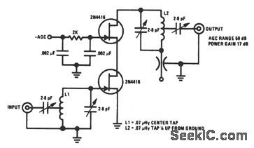
This JFET cascode circuit features low crossmodulation, large-signal handling ability, no neutralization, and an AGC that is controlled by biasing the upper cascode JFET. The only special requirement of this circuit is that IDSS of the upper JFET must be greater than that of the lower JFET. (View)
View full Circuit Diagram | Comments | Reading(0)
Simple_fast_V_F_converter
Published:2009/7/23 23:29:00 Author:Jessie
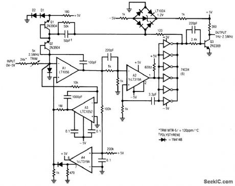
Fig. 12-8 The 2.5-MHz output of this circuit settles from a full-scale input in 3μs while maintaining 0.05% linearity with 50 ppm/℃ drift. To trim, apply 5.000 V and adjust the 2.5MHz trim for 2.500 MHz at the output. No zero trim is required. A TTL-compatible (5 V) output is available at the Q3 collector. Linear Technology. Linear Applications Handbook 1990, p AN14-4. (View)
View full Circuit Diagram | Comments | Reading(855)
Amplifier_with_±120_V_output_
Published:2009/7/23 23:29:00 Author:Jessie
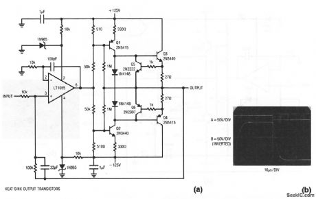
This amplifier provides a±120-V output. The full-power bandwidth is 15-kHz with a slew rate of about 20 V/μs. Figure 1-13B shows the results with a ±12-V input (trace A). The output (trace B) is a cleanly-damped 240 Vpp pulse. (View)
View full Circuit Diagram | Comments | Reading(776)
15_A_positive_adjustable_voltage_regulator
Published:2009/7/23 23:29:00 Author:Jessie
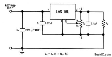
The LAS15U is a four-terminal adjustable regulator IC with an output range from +4 to +30 V, providing remote-sense capability with a single pot. Characteristics are shown in Fig.7-32B, 7-32C, and 7-32D. (View)
View full Circuit Diagram | Comments | Reading(852)
ROUGH_SERVO_REGULATOR
Published:2009/7/23 23:29:00 Author:Jessie

Drives auto-transformer to establish narrow range of fine regulator for dose control of field of large electromagnet having 50-kw excitation.-A. M. Patlach, Precision Servo Regulator Controls High. Power Magnetic Field, Electronics, 33:45, p 66-69. (View)
View full Circuit Diagram | Comments | Reading(713)
| Pages:1112/2234 At 2011011102110311041105110611071108110911101111111211131114111511161117111811191120Under 20 |
Circuit Categories
power supply circuit
Amplifier Circuit
Basic Circuit
LED and Light Circuit
Sensor Circuit
Signal Processing
Electrical Equipment Circuit
Control Circuit
Remote Control Circuit
A/D-D/A Converter Circuit
Audio Circuit
Measuring and Test Circuit
Communication Circuit
Computer-Related Circuit
555 Circuit
Automotive Circuit
Repairing Circuit