
Circuit Diagram
Index 1117
CW_FILTER_FOR_INTERFERENCE
Published:2009/7/3 3:41:00 Author:May
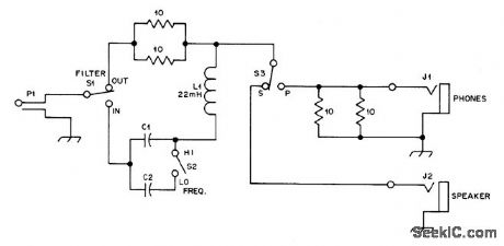
Audio bandpass filter, designed for connection between loudspeaker jack of receiver and external loudspeaker or phone, has half-power bandwidth of about 70 Hz but rolls off gradually without causing ringing, Series LC combination, connected in hot line to loudspeaker,looks like 5-ohm re sistance at resonance, cutting signal amplitude about in half. At Iower frequencies filter looks like large capacitive reactance and at higher frequencies it resembles large inductive reactance, both causing high attenuation. Filter thus discriminates against all except switch-selected resonant frequency, either 760 or 1070 Hz.Choose best frequency for particular receiving situation by trial.-F. Noble, A Passive CW Filter to improve Selectivity, QST, Nov. 1977, p 34-35. (View)
View full Circuit Diagram | Comments | Reading(1289)
DIGI_TACH
Published:2009/7/3 3:40:00 Author:May
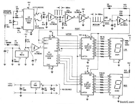
The Digi-Tach contains a master-clock circuits (U6), latch and reset pulse generators (U2-b-U2-d), input signal conditioner (U1, U2-a), pulse counter (U3), display and display drivers (DIS1, DIS2, U4, and U5), and a voltage regulator (U7). As an added feature, Digi-Tach contains a dimmer circuit (U2-e). (View)
View full Circuit Diagram | Comments | Reading(1856)
GENERAL_PURPOSE_RF_DETECTOR
Published:2009/7/3 3:40:00 Author:May
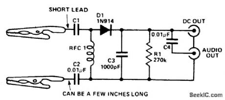
Circuit NotesThis circuit provides a dc output to a meter and an audio output (if necessary) for checking transmitters or modulated signals. It can be used also as a field strength meter or transmitter monitor. (View)
View full Circuit Diagram | Comments | Reading(1133)
THREE_INPUT_IFF_MIXER
Published:2009/7/23 23:37:00 Author:Jessie
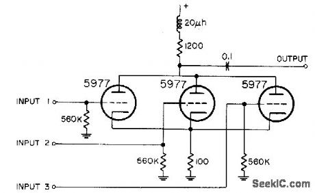
Common-plate connection serves for combining three iff signals. Common cathode resistor provides some degeneration.-NBS, Handbook Preferred Circuits Navy Aeronautical Electronic Equipment, Vol. 1, Electron Tube Circuits, 1963, p N4-3. (View)
View full Circuit Diagram | Comments | Reading(730)
60_Hz_TUNABLE_NOTCH
Published:2009/7/3 3:39:00 Author:May
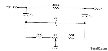
Can be used to minimize hum pick up from AC line. Circuit tunes from 40 to 120 Hz with single pot. Artide gives design equations. With unmeasured ceramic disk capacitors and 5% resistors, notch depth at 60 Hz was 44.5 dB. By selecting capacitors with equal values and replacing 333K with 500K trimpot, careful adiustment increases notch depth to 57 dB.-C. Hall, Tunable RC Notch Filter, Ham Fladio, Sept. 1975, p 16-20. (View)
View full Circuit Diagram | Comments | Reading(749)
505_MHz_BANDPASS
Published:2009/7/3 3:39:00 Author:May
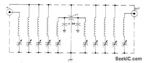
Provides 60% band-width with only 4-dB insertion loss Each coil is about 2.2μH,and trimmer capacitors are 1.5-7 pF Sweep signal generator and 5-in CRO are essential for alignment.-P. H.Sellers, 50-MHz Bandpass Filter, Ham Radio, Aug. 1976, p 70-71. (View)
View full Circuit Diagram | Comments | Reading(799)
_12_V_flash_memory_programming_supply
Published:2009/7/23 23:37:00 Author:Jessie
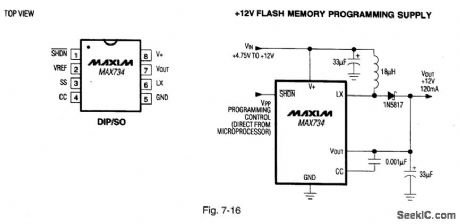
Figure 7-16 shows a MAX734 connected as a flash-memory programming supply. Typical efficiency is 85%. The IC also has a logic-controlled shutdown pin that allows direct microprocessor control. MAXIM HIGH-RELIABILITY DATA Book, 1993, P. 4-65. (View)
View full Circuit Diagram | Comments | Reading(667)
SINGLE_INJECTOR_TRACER
Published:2009/7/3 3:38:00 Author:May
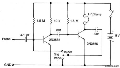
Circuit NotesThis circuit will provide a nominal square wave output in the audio range in the Inject mode, the harmonics of which should be heard at several MHz. In the Trace mode the non-linear operation of the amplifter will detect modulated rf signals which will be filtered by the.0.01μF capacitor and heard in the headphones. (View)
View full Circuit Diagram | Comments | Reading(580)
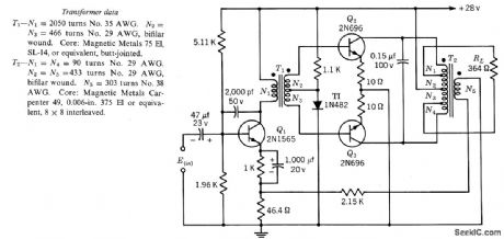
35_W_CLASS_B_SERVO_AMPIIFIER
Published:2009/7/23 23:36:00 Author:Jessie
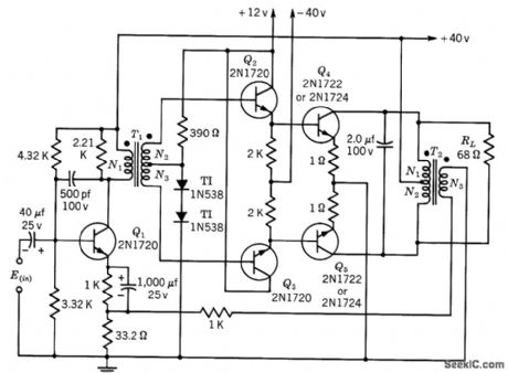
Gives power gain of 45 db. Voltage amplification is constant within 1.5 db of 36.5 db. Transformer data is for 400-cps operation.-Texas Instruments Inc., Transistor Circuit Design, McGraw-Hill, N.Y., 1963, p 244. (View)
View full Circuit Diagram | Comments | Reading(785)
ELLIPTIC_HIGH_PASS_LOW_PASS
Published:2009/7/3 3:38:00 Author:May
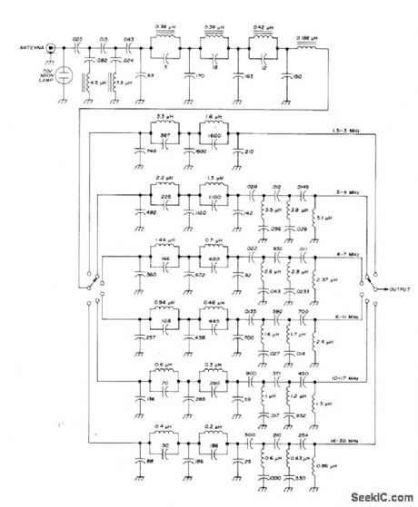
Covers 1.45 to 32 MHz in six steps, for use at front end of high-frequency communication receiver to suppress unwanted broadcast signals. Low-pass filter section, acting with one of six following low-pass sections, gives over 90-dB image suppression. Special Bessel-Cauer elliptic filter having Chebyshev response in passband provides required 50-ohm impedance matching so filters can be cascaded.-U. L. Rohde, Optimum Design for High-Frequency Communications Recoivers, Ham Fladio, Oct. 1976, p 10-25.
(View)
View full Circuit Diagram | Comments | Reading(1254)
BIOELECTRIC_VOLTMETER
Published:2009/7/3 3:36:00 Author:May
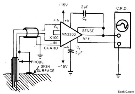
Used to measurebioelectric phenomena involving both DC and waveform characteristics with amplitudes ofabout 10 mV Since electrodes have impedanceof 20,000 to 100,000 ohms、guard terminal mustbe used to drive input shield Bias-current return comes from ground plate on skin.Fixedgain of 1000 gives absolute measure of inputvoltage magnitude.-R,Duris,Instrumentation Amplifiers-They're Great Problem Solvers When correctly Applied,EDN Magazine, Sept5,1977,p 133-135. (View)
View full Circuit Diagram | Comments | Reading(855)
TWO_INPUT_THREE_OUTPUT_MIXER
Published:2009/7/23 23:36:00 Author:Jessie
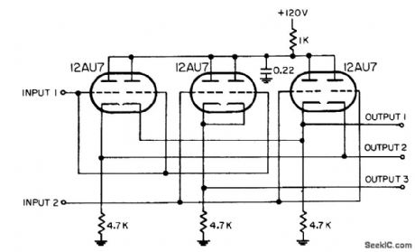
Combines two inputs and distributes them to each of three independent outputs, which are con netted to separate indicators.-NBS, Handbook Preferred Circuits Navy Aeronautical Electronic Equipment, Vol. 1, Electron Tube Circuits, 1963, p N4-3. (View)
View full Circuit Diagram | Comments | Reading(1068)
15_W_CLASS_B_SERVO_AMPLIFIER
Published:2009/7/23 23:36:00 Author:Jessie
Gives power gain of 38 db. Voltage amplification is constant within 1.5 db of 40.5 db. Transformer data is for 400-cps operation.-Texas Instruments Inc., Transistor Circuit Design, McGraw-Hill, N.Y., 1963, p 240. (View)
View full Circuit Diagram | Comments | Reading(826)
IGNITION_TIMING_LIGHT
Published:2009/7/3 3:35:00 Author:May
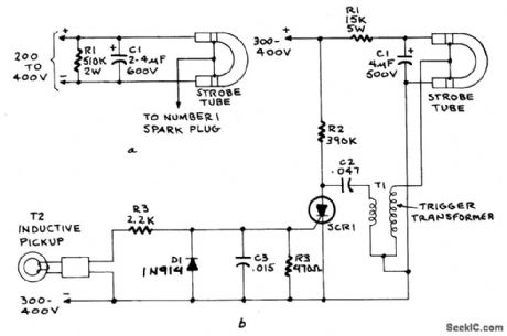
Figure A shows the circuit of a direct-trigger timing light. The trigger voltage is taken from the car's ignition circuit by a direct connection to a spark plug. A circuit using an inductive pickup is shown in Fig. B. A trigger transformer is used to develop the high-voltage pulse for triggering. The triggering circuit consists of T1, C1, SCR1, inductive pickup coil T2, and the waveshaping components in the SCR's gate circuit.When the spark plug fires, it induces a pulse in pickup coil T2 that triggers the SCR gate. The SCR fires and discharges C2 through the primary of T1. The secondary of T1 feeds a high-voltage pulse to the trigger electrode of the flash tube. That pulse causes the gas-usually neon or xenon-to ionize. The ionized gas provides a low-resistance path for Ct to discharge, thereby creating a brilliant flash of light.Resistor R1 limits current from the supply as the tube fires. When C1 is fully discharged the strobe tube cuts off and returns to its high-resistance state. The current through R2 is not enough to sustain conduction through SCR1, so it cuts off and remains off until it is re-triggered by a gate pulse. (View)
View full Circuit Diagram | Comments | Reading(7839)
DELAY_CIRCUITS_FOR_HEADLIGHTS
Published:2009/7/3 3:33:00 Author:May
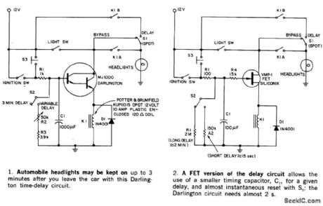
This circuit keeps an automobile's headlights on temporarily. It also will turn the lights off, even if you forget to flip the light switch. The circuit's shut-off delay is actuated only after both the ignition and light switches have been on, and only if the ignition switch is tumed off first. If the light switch is tumed off ftrst, no delay results. Parking and brake-light operation is not affected. The maximum time out can be up to 3 minutes in part 1 and hours with the circuit in part 2, depending on the relay selected and the value of R2. A switch S2 can be used to permit selection of either a short or long delay.Momentary switch S3 can restart circuit timing before the time-out is completed. A bypass switch, S1 removes the delay action. (View)
View full Circuit Diagram | Comments | Reading(656)
TWIN_LED_TUNING_INDICATOR
Published:2009/7/3 3:33:00 Author:May
Provides maximum sensitivity at correct tuning point and indicates direction of mistuning. Both lamps are in feedback loop of one opamp, connected to serve as highlysensitive null detector.When set is tuned correctly, output of this opamp is at midpoint of supply voltage and neither LED is lit. Circuit is used with RCA CA3089 IF chip in which AFC output is a current. Capacitor across first 741 opamp removes modulation components from this input.-M. G. Smart, F.M. Tuning Indicators, Wireless World,Dec.1974,p 497. (View)
View full Circuit Diagram | Comments | Reading(1377)
MICROVOLT_PROBE
Published:2009/7/3 3:33:00 Author:May
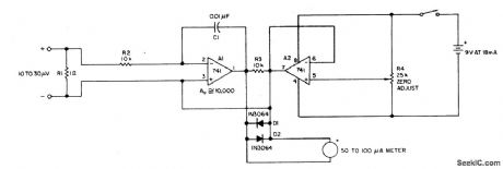
Circuit NotesThe current tracer helps locate a defective IC that is loading down the power supply. The tracer amplifies the small voltage drop caused by current flow along a fraction of an inch of PC wiring and drives an ordinary microammeter. Needle-point test probes are used to contact the edge of a PC trace and to follow the current to determine which branch the current takes. One-half of a dual 741 op amp forms a dc amplifter with ac feedback to prevent oscillations and hum-pickup problems. It drives a 50-to-100 μA me-ter. The other op amp provides a center tap for the 9 V battery supply and zero adjustment with R4. Two diodes protect the meter. Resistor R1 eliminates the necessity for shorting the probes when the meter is zeroed. The value of 1 ohm is large when compared with the resistance of the meter leads plus the bridged portion of PC wiring. (View)
View full Circuit Diagram | Comments | Reading(1362)
Single_cell_V_F_converter_1_Hz_to_1_kHz
Published:2009/7/23 23:35:00 Author:Jessie
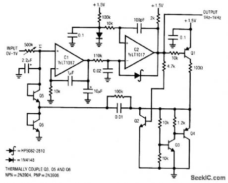
Fig. 12-11 This circuit operates from a single 1.5-Vbattery, with only 125-μA current drain, to provide a range from 1Hz to 1kHz. Drift is 250ppm/℃. Battery discharge introduces less than 1% error over 1000 hours of operation. To trim, set the input to 1.000V and adjust the 500-kΩ potentiometer for an output of 1.000 kHz. (View)
View full Circuit Diagram | Comments | Reading(887)
ICE_FORMATION_ALARM
Published:2009/7/3 3:31:00 Author:May
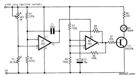
The circuit warns car drivers when the air temperature close to the ground approaches 0℃, thereby indicating possible formation of ice on the road surface. Op amp A1 is wired as a voltage level sensor. Op amp A2 is wired as an astable multivibrator which, by means of current buffer Tr1, flashes a filament lamp at about 1 Hz. As air temperature falls, a point is reached when the voltage at pin 2 just rises above the volt-age at pin 1. The output of A1 is immediately driven into positive saturation, since it is operated open loop. This positive output voltage powers A2 through its V + connection on pin 9, starting the oscillator. The thermistor is a glass bead type with a resistance of about 20 MΩ at 20℃. VR1 is adjusted so that the lamp starts flashing when the air temperature is 1 to 2℃. (View)
View full Circuit Diagram | Comments | Reading(1638)
PREFERRED_LOW_LEVEL_PULSE_CATHODE_FOLLOWER
Published:2009/7/23 23:35:00 Author:Jessie
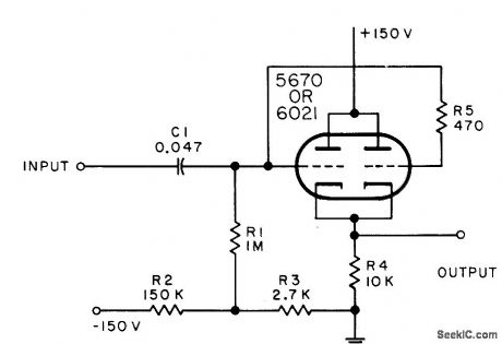
Used to couple output of low-level video stage to resistive load in applications where high-duty-factor signal makes direct coupling desirable.-NBS, Handbook Preferred Circuits Navy Aeronautical Electronic Equipment, Vol. I, Electron Tube Circuits, 1963, PC 22, p 22-2. (View)
View full Circuit Diagram | Comments | Reading(780)
| Pages:1117/2234 At 2011011102110311041105110611071108110911101111111211131114111511161117111811191120Under 20 |
Circuit Categories
power supply circuit
Amplifier Circuit
Basic Circuit
LED and Light Circuit
Sensor Circuit
Signal Processing
Electrical Equipment Circuit
Control Circuit
Remote Control Circuit
A/D-D/A Converter Circuit
Audio Circuit
Measuring and Test Circuit
Communication Circuit
Computer-Related Circuit
555 Circuit
Automotive Circuit
Repairing Circuit