
Circuit Diagram
Index 1104
02_TO_18_CPS
Published:2009/7/23 22:38:00 Author:Jessie
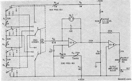
Provides low-frequency 5-V sweeps of high linearity, to complement conventional signal generators having maximum accuracy at higher sweeps.-A. Angelone, Subaudio Sawtooth Generator Gives One-Percent Linearity, Electronics, 34:48, p 42-43. (View)
View full Circuit Diagram | Comments | Reading(607)
SONAR_THUMPER
Published:2009/7/23 22:38:00 Author:Jessie
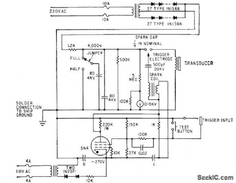
Strobotron tube circuit energizes spark coil, ionizing spark gap and discharging bank of 4,000-v capacitors through underwater transducer coil, causing adjacent aluminum plate to produce high-power sound pulse that penetrates sediment layers and bedrock for oceanographic research.-New Sonar Thumper Charts Ocean Subbottom, Electronics, 34:5, p 56:57. (View)
View full Circuit Diagram | Comments | Reading(760)
CLUTCH_COIL_FOR_TIMER_MOTOR
Published:2009/7/23 22:38:00 Author:Jessie
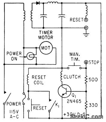
Start-and-stop signals are applied to stop jack, for automatic timing. Manual-timing pushbutton applies 0-v signal to stop jock, to make Q1 conduct. Fast switching rime of transistor permits reading time to within 0.005 millisec.-F. W. Kear, Electromechanical Timer for Lab Applications, Electronics, 36:7, p 78-79. (View)
View full Circuit Diagram | Comments | Reading(762)
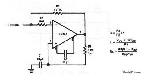
Variable_capacitance_multiplier
Published:2009/7/23 22:38:00 Author:Jessie
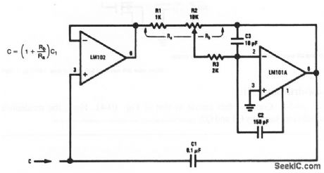
This circuit appears as an adjustable capacitance (set by R2) to the input. (View)
View full Circuit Diagram | Comments | Reading(673)
Step_up_voltage_regulator_with_voltage_dependent_oscillator
Published:2009/7/23 22:37:00 Author:Jessie
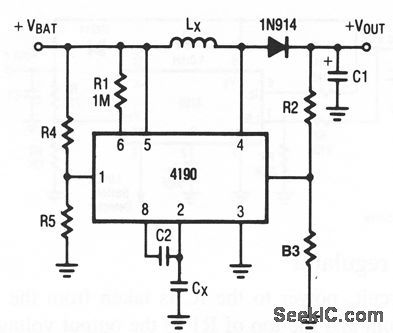
The circuit of Fig. 4-9 offers a compromise between load-current capability and output ripple (increased load current typically causes increased ripple). Component values are tailored to circuit requirements, as described for Fig.4-2, except as follows:
Typical component values are: R2= 330 kΩ, Rs=150 kΩ, Cx 100 pF, C2=100 pF. With these values, VTH is 4-1 V and Fo= 24 kHz. If the IC oscillator appears to be destabilized, or if there is excessive low-frequency ripple, look for stray capacitance at pin 7. Also, try a 100-pF to 10-nF capacitor in parallel with R2.
(View)
View full Circuit Diagram | Comments | Reading(768)
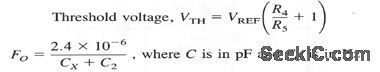
VOLTAGE_CONTROLLED_RAMP_TRIGOER
Published:2009/7/23 22:37:00 Author:Jessie
Provides ramp output with or without positive and negative trigger pulses over 6:1 linear range of frequency control. For values of C from 0.001 to 10 mfd, frequency range is 10 cps to 20 kc.-M. S. Tatch, Voltage-Controlled Ramp/Trigger Generator, FEE, 12:3, p 71. (View)
View full Circuit Diagram | Comments | Reading(695)
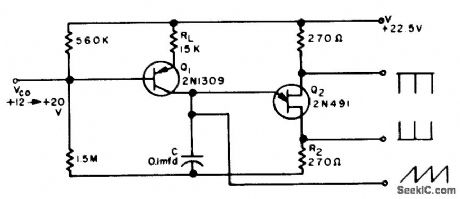
ENCODER_OSCILLATOR
Published:2009/7/23 22:37:00 Author:Jessie
Used to trigger 24 elapsed-time counters until end of storage period, for storing and reading out elapsed time between consecutive but randomly occurring events. Gates are designed to maintain amplitude of trigger pulse above half the supply voltage over wide temperature range.-R. J. Kelso and J. C. Groce, Encoder Measures Random Event Time Intervals, Electronics, 32:12, p 48-51. (View)
View full Circuit Diagram | Comments | Reading(758)
Negative_ca_pacitancem_ultiplier
Published:2009/7/23 22:37:00 Author:Jessie
This circuit appears as a negative capacitance to the input. (View)
View full Circuit Diagram | Comments | Reading(651)
RAMP_GENERATOR
Published:2009/7/23 22:36:00 Author:Jessie

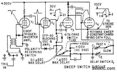
Produces positive-going ramp with 100-V amplitude when input trigger pulse is applied. Time duration of ramp can be set at 0.1 or 1 microsec. Time stability is better than 0.1 millimicrosec for long time intervals.-W. E. Bushor, Sample Method Displays Millimicrosecond Pulses, Electronics, 32:31, p 69-71. (View)
View full Circuit Diagram | Comments | Reading(0)
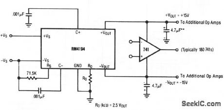
One_decade_low_distortion_sine_wave_generator_
Published:2009/7/23 22:54:00 Author:Jessie
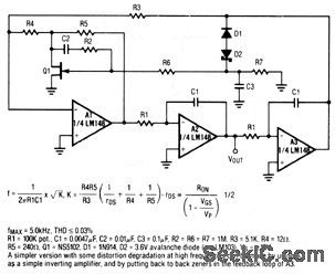
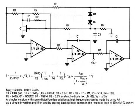
This circuit uses three sections of an LM148 op amp. The frequency of VOUT is set by R1, and is 5 kHz maximum with the values shown. Raytheon Linear Integrated Circuts, 1989, p. 4-263. (View)
View full Circuit Diagram | Comments | Reading(1098)
CB_WITHOUT_SEND_RECEIVE_RELAY
Published:2009/7/23 22:54:00 Author:Jessie
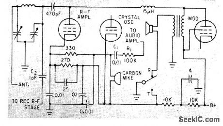
With switch in transmit position, carbon mike gets some of r-f amplifier current, and audio signals in last audio stage Heising-modulate transmitter. During reception, receiver local oscillator gets plate voltage, loudspeaker is connected, and cathodes of transmitter cry still oscillator and r-f amplifier are made positive to cut them off.-L. Solomon, Citizens Band Equipmenl Design, Electronics, 33:45, p 70-72. (View)
View full Circuit Diagram | Comments | Reading(701)
50_KC_SAWTOOTH
Published:2009/7/23 22:54:00 Author:Jessie
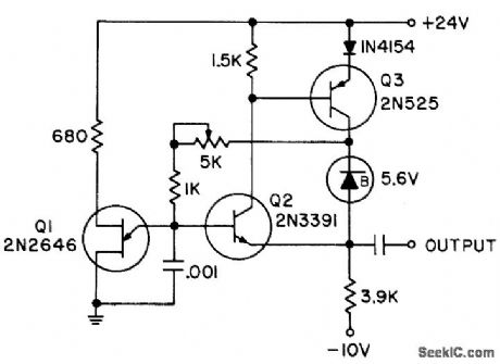
Uses bootstrap charging circuit, with constant voltage maintained across charging resistor by zener diode and emitter-follower amplifier Q3, so capacitor charging current is constant over complete cycle.- Transistor Manual, Seventh Edition, General Electric Co., 1964, p 319. (View)
View full Circuit Diagram | Comments | Reading(615)
160_W_PEP_broadband_linear_amplifier
Published:2009/7/23 22:54:00 Author:Jessie
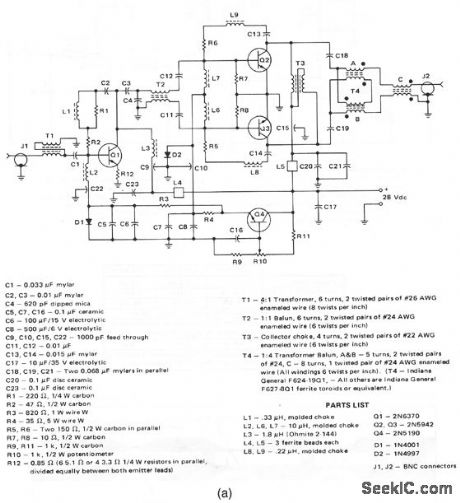
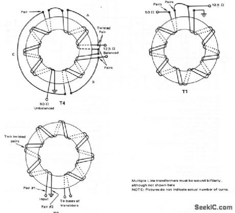
This circuit provides 160-W (PEP) into a 50-Ω load with an IMD (intermodulation distortion) of -30 dB Or better,Figure 2-50B shows the transformer details. (View)
View full Circuit Diagram | Comments | Reading(0)
CLASS_C_CB_TRANSMITTER
Published:2009/7/23 22:53:00 Author:Jessie
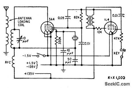
Control signal may be tone-modulated a-m, with different tones to control several functions on one frequency.-L. G. Sands, Citizens Radio Revision Spurs Equipment Design, Electronics, 32:15, p 55-57. (View)
View full Circuit Diagram | Comments | Reading(1049)
LINEAR_SAWTOOTH_1
Published:2009/7/23 22:53:00 Author:Jessie
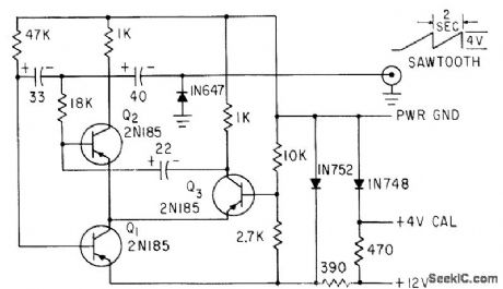
Develops signal with 4-V amplitude and 2.sec period.-O. C. Hay-cock and K. D. Baker, Measuring Antenna Impedance in 34:2, p 88-92. (View)
View full Circuit Diagram | Comments | Reading(689)
195_KC_SONAR_F_M_MODULATOR
Published:2009/7/23 22:53:00 Author:Jessie
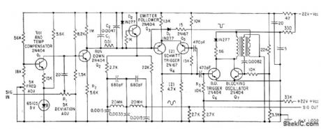
Used in recording signals from active sonar on magnetic tape, for later playback to control land-based sonar used in training operators. Modulator is basically sawtooth generator whose repetition frequency is changed by amplitude of modulating input signal.-M. H. Damon, Jr., Tape Target Classifier Trains Sonar Operators, Electronics, 33:13, p 65-69. (View)
View full Circuit Diagram | Comments | Reading(597)
Balanced_dual_tracking_regulator_
Published:2009/7/23 22:53:00 Author:Jessie
This circuit provides blanced output voltage that can be varied between±50 and ±42 mV by selection of Ro,with load currents of 200mV. This circuit is particularly useful for op-amp (chapter 10) applications, (View)
View full Circuit Diagram | Comments | Reading(792)
Dual_preregulated_off_line_linear_supply
Published:2009/7/23 22:53:00 Author:Jessie
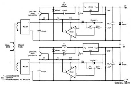
This circuit provides a +12-V and a -12-V output, both of which are capable of delivering 1.5 A. (View)
View full Circuit Diagram | Comments | Reading(589)
High_side_MOSPET_driver
Published:2009/7/23 22:53:00 Author:Jessie
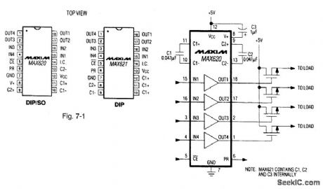
Figure 7-1 shows a MAX620 connected to power high-side switching and control circuits. The charge pump delivers a regulated output voltage that is 11 V higher than VCC to the drivers. In turn, the drivers translate a TTL/CMOS input signal to a noninverted output that swings from ground to the high-side voltage. The continuous driver-output current is 25 mA, with a typical quiescent current of 70 μA. The MAX620 requires three external charge-pump capacitors. The MAX621 has internal capacitors. MAXIM NEW RELEASES DATA Book, 1992, P. 4-19. (View)
View full Circuit Diagram | Comments | Reading(960)
THYRATRON_SWITCH_TRANSMITTER
Published:2009/7/23 22:52:00 Author:Jessie
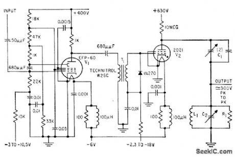
Receives 100 or 1,000-pps trigger pulse from rate generator and produces pulse of r-f oscillations that decays from maximum peak-to-peak of 300 v, for measuring ultrasonic velocity in metal test sample. Pulse litter is less than 1 millimicrosec, for accurate measurement of lime interval between ultrasonic echo pulses.-R. L. Forgacs, Removing the Jitter from Thyratron Pulses, Electronics, 32:20, p 60-61. (View)
View full Circuit Diagram | Comments | Reading(706)
| Pages:1104/2234 At 2011011102110311041105110611071108110911101111111211131114111511161117111811191120Under 20 |
Circuit Categories
power supply circuit
Amplifier Circuit
Basic Circuit
LED and Light Circuit
Sensor Circuit
Signal Processing
Electrical Equipment Circuit
Control Circuit
Remote Control Circuit
A/D-D/A Converter Circuit
Audio Circuit
Measuring and Test Circuit
Communication Circuit
Computer-Related Circuit
555 Circuit
Automotive Circuit
Repairing Circuit