
Circuit Diagram
Index 1110
Flash_memory_yorogramming_module_120_mA
Published:2009/7/23 23:53:00 Author:Jessie
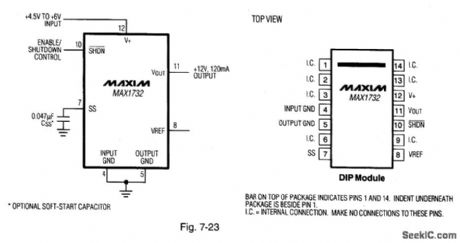
Figure 7-23 shows a MAX1732 connected as a flash-memory programming module. This function is similar to that performed by the circuit of Fig. 7-16, but with only one extemal capadtor required. Quiescent current is 1.7 mA, with 70-μA shutdown current. MAXIM NEW RELEAsES DATA BOOK, 1994, P. 4-15. (View)
View full Circuit Diagram | Comments | Reading(740)
8_A_positive_adjustable_voltage_regulator
Published:2009/7/23 23:53:00 Author:Jessie
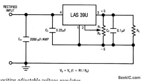
The LAS39U is a four-terminal adjustable-regulator IC with an output range from +4 to + 16 V, providing remote sensing from a single pot.Characteristics are shown in Fig. 7-50B, 7-50C, and 7-50D. (View)
View full Circuit Diagram | Comments | Reading(837)
Low_noise_technique_with_parallel_amplifiers
Published:2009/7/23 23:53:00 Author:Jessie
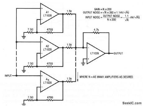
This circuit operates on a statistical noise-reduction technique. Noise decreases by the √N of the number of devices in parallel. For example, for nine paralleled amplifiers, noise would decrease by a factor of three, to about 0.33 nV √Hz at 1 kHz. A potential penalty of this connection is that the input-current noise increases by √N devices. (View)
View full Circuit Diagram | Comments | Reading(1078)
Basic_F_V_converter
Published:2009/7/23 23:53:00 Author:Jessie
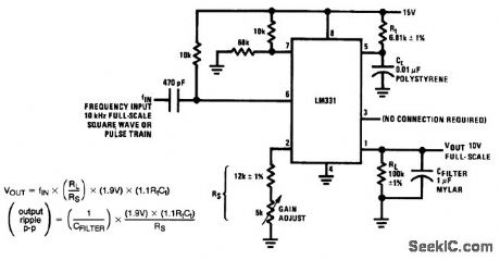
Fig. 12-19 This circuit produces a 10-V output for a 10-kHz full-scale input (square-waves or pulses). Linearity is about 0.06% at full scale. As is the case with most F/V converters, there is a tradeoff between ripple versus response time. With CFILTER at 1μF, as shown, the output ripple is about 13 mVp-p, with a slow 0.6-s settling time. If CFILTER is decreased, the response time is quicker, but ripple increases by the same factor. An increase in CFILTER produces the opposite results. To trim, set the 5-kΩ gain adjust for 10 V out with a 10-kHz input. National Semiconductor, Linear Applications Handbook 1991 p 1253. (View)
View full Circuit Diagram | Comments | Reading(747)
PREFERRED_AMPLIFICATION_70_PREAMPLIFIER
Published:2009/7/23 23:53:00 Author:Jessie
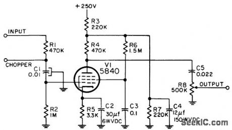
Used with instrument servo motor controller to increase available gain. Chopper is used with d-c inputs only. Frequency range is 380 to 420 cps.-NBS, Handbook Preferred Circuits Navy Aeronautical Electronic Equipment, Vol. I, Electron Tube Circuits, 1963, PC 72, p 72-2. (View)
View full Circuit Diagram | Comments | Reading(738)
Enable_and_disable_timing_tests
Published:2009/7/23 23:53:00 Author:Jessie
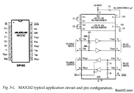
Figure 3-L shows the typical application circuit and pin configuration for the MAX242. This IC is similar to the MAX220, except that the receiver channels can be enabled and disabled, and all four channels can be shut down by external signals. Figures 3-M and 3-N show test circuits and waveforms for receiver-channel enable/disable, and transmitter-channel disable timing. (View)
View full Circuit Diagram | Comments | Reading(825)
PENTODE_MIXER
Published:2009/7/23 23:32:00 Author:Jessie

Negative video plus iff signals are inserted at grid, while range strobe, from cathode output of blocking oscillator, is applied to cathode.-NBS, Handbook Preferred Circuits Navy Aeronautical Electronic Equipment, Vol.1, Electron Tube Circuits, 1963, p N4-4. (View)
View full Circuit Diagram | Comments | Reading(805)
Low_cost_VHF_broadband_amplifier_160_to_174_MHz
Published:2009/7/23 23:24:00 Author:Jessie
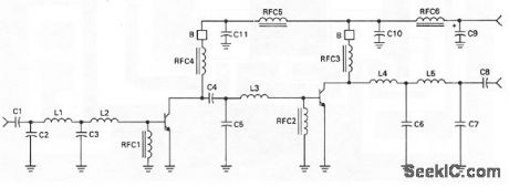
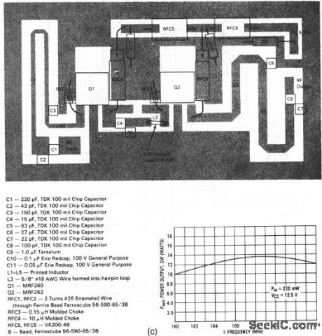
This circuit has a power gain of about 18 dB overthe frequency range.Figure 2-62B shows the board layout and components list, and Fig,2-62C showsthe power output Versus frequency. (View)
View full Circuit Diagram | Comments | Reading(1319)
NONADDITIVE_COMMON_PLATE_MIXER
Published:2009/7/23 23:24:00 Author:Jessie
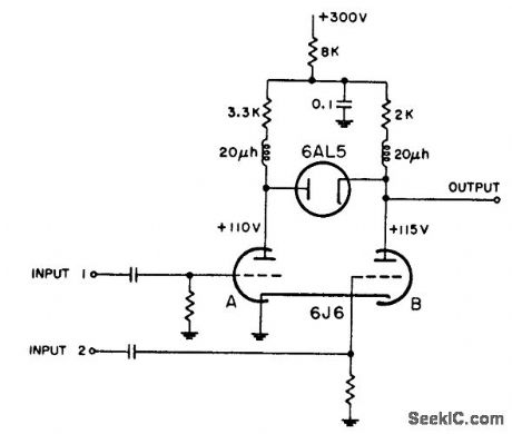
Plates ore coupled by diode that is nonconducting because plate is at lower potential than cathode. If input pulses are not coincident, negative pulse of sufficient amplitude at either input will appear at output. If inputs are coincident, positive pulse appearing at plate of section A will not appear at output unless of sufficient amplitude to overcome bias established by positive output from section B. Radar video must be applied to input 2, since output of section A must overcome 5-v diode bias,-NBS, Handbook Preferred Circuits Navy Aeronautical Electronic Equipment, Vol. 1, Electron Tube Circuits, 1963, p N4-4. (View)
View full Circuit Diagram | Comments | Reading(681)
Amplifier_with_CMOS_inverter_output_stage
Published:2009/7/23 23:24:00 Author:Jessie
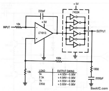
This circuit shows a simple, inexpensive way to extend the output swing of an amplifier to the supply rails. The circuit is particularly useful in 5-V analog systems, where improvements in available output swing are desirable to maximize signal-processing range. As shown by the table, output swing is quite close to the positive rail, particularly at loads below several mA. (View)
View full Circuit Diagram | Comments | Reading(868)
3_A_positive_fixed_current_regulator
Published:2009/7/23 23:24:00 Author:Jessie
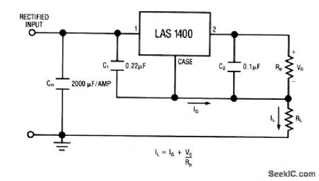
This circuit uses the LAS1400 series voltage regulator (Fig. 7-28A) as a fixed-current regulator. Characteristics are shown in Fig. 7-28B, 7-28C, and 7-28D. (View)
View full Circuit Diagram | Comments | Reading(610)
6_W_HIGH_EFFICIENCY_AMPLIFIER
Published:2009/7/23 23:23:00 Author:Jessie
Overall efficiency is 55%. Design equations are given.-Texas Instruments Inc., Transistor Circuit Design, McGraw-Hill, N.Y., 1963, p 249. (View)
View full Circuit Diagram | Comments | Reading(766)
PREFERRED_LOW_LEVEL_COMMON_PLATE_MIXER
Published:2009/7/23 23:23:00 Author:Jessie
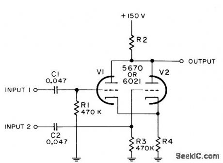
Combining of video signals with pulses is accompanied by inversion of input signal. Value of R4 is 270 ohms for 5670 and 470 ohms for 6021. R2 is 680 ohms for 5670 and 1 K for 6021. Input signals must be positive.-NBS, Handbook Preferred Circuits Navy Aeronautical Electronic Equipment, Vol. I, Electron Tube Circuits, 1963, PC 24, p 24-2. (View)
View full Circuit Diagram | Comments | Reading(2632)
Quartz_stabilized_V_F_converter_external_clock
Published:2009/7/23 23:23:00 Author:Jessie
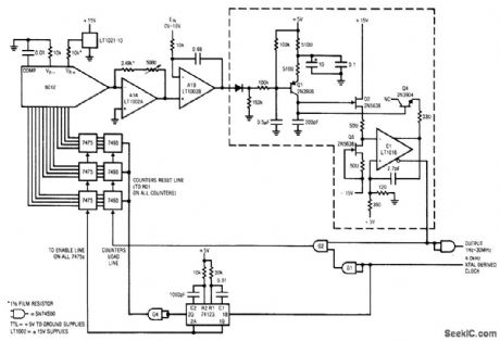
Fig. 12-6 This circuit requires an external4-kHz clock, but it provides very high linearity (typically 0.025%, limited by the 6012 DAC). Range is 1 Hz to 30 MHz, with a typical full-scale drift of 50 ppm/℃, and a zero-point error of about 0.3μV/℃. The circuit is trimmed at the 30-MHz end with the 5000-0 feedback resistor of A1A. Linear Technology linear Applications Handbook, 1990 p AN13-11. (View)
View full Circuit Diagram | Comments | Reading(701)
Ultra_frtst_amplifier_with_current_boost
Published:2009/7/23 23:23:00 Author:Jessie
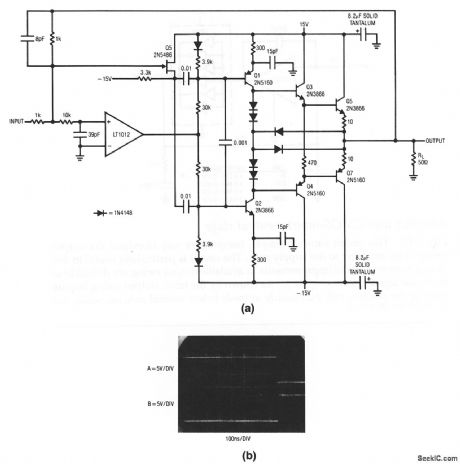
This current-boosted amplifier features a slew rate in excess of 1000 V/μs, a full power bandwidth of 7.5 MHz, and a 3-dB point of 14 MHz. Figure 1-9B shows the circuit driving a 10-V pulse into a 50-Ω load. Trace A is input, Trace B is output. (View)
View full Circuit Diagram | Comments | Reading(897)
THREE_INPUT_TWO_OUTPUT_MIXER
Published:2009/7/23 23:23:00 Author:Jessie
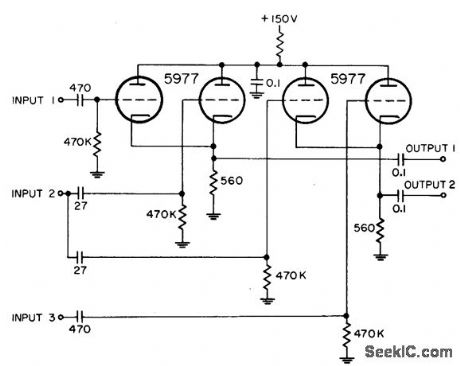
Uses two separate common-cathode video mixers. Same heading markers are inserted into both mixers front input 2, while other inputs handle independent markers.-NBS, Hand-book Preferred Circuits Navy Aeronautical Electronic Equipment, Vol.1, Electron Tube Circuits, 1963, p N4-3. (View)
View full Circuit Diagram | Comments | Reading(685)
Low_cost_VHF_broadband_amplifier_136_to_160_MHz
Published:2009/7/23 23:23:00 Author:Jessie
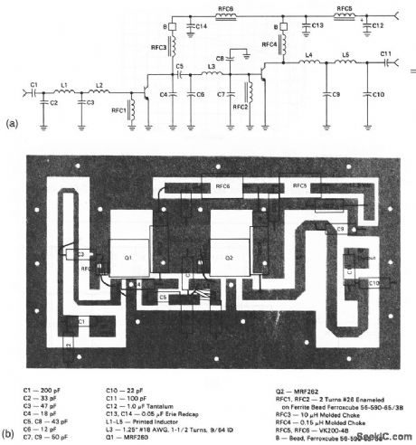
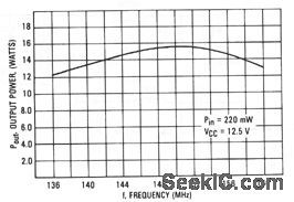
This circuit has a power gain of about 19 dB over the frequency range.Figure 2-61B shows the board layout and components list, and Fig. 2-61C shows the power output versus frequency. (View)
View full Circuit Diagram | Comments | Reading(1548)
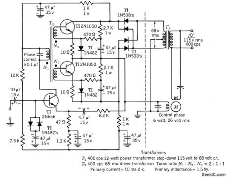
2_W_HIGH_EFFICIENCY_SERVO_AMPLIFIER
Published:2009/7/23 23:22:00 Author:Jessie
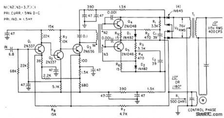
Voltage gain with feedback loop is 10,000, efficiency is above 50%, and gain changes less than 3 db between -55 and +125℃ .No center tap is required on control winding of moron-J. A. Walston and J. E. Setliff, Designing Servo Amplifiers for High Efficiency, Electronics, 3616, p 62-63. (View)
View full Circuit Diagram | Comments | Reading(728)
3_A_positive_adjustable_voltage_regulator
Published:2009/7/23 23:22:00 Author:Jessie
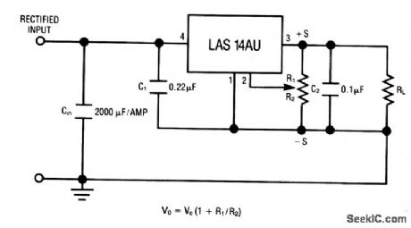
The LAS14AU is a four-terminal adjustable regulator IC with an output range from +4 to +30V, providing remote-sense capability with a single pot. Characteristics are shown in Fig. 7-28B, 7-28C, and 7-28D. (View)
View full Circuit Diagram | Comments | Reading(871)
Lock_in_amplifier
Published:2009/7/23 23:19:00 Author:Jessie
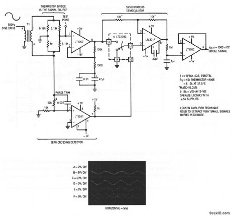
carrier-modulated output of the signal source. Because the desired signal information is contained within the carrier, the system constitutes an extremely narrowband amplifier. Noncarrier related components are rejected, and the amplifier passes only signals, which are coherent with the carrier. The amplifier can extract a signal 120 dB below the noise level. The signal source is a thermistor bridge, which detects extremely small temperature shifts in a biochemical microcalorimetry reaction chamber. To trim, adjust the phase potentiometer so that switching occurs when the carrier crosses through zero. (View)
View full Circuit Diagram | Comments | Reading(1967)
| Pages:1110/2234 At 2011011102110311041105110611071108110911101111111211131114111511161117111811191120Under 20 |
Circuit Categories
power supply circuit
Amplifier Circuit
Basic Circuit
LED and Light Circuit
Sensor Circuit
Signal Processing
Electrical Equipment Circuit
Control Circuit
Remote Control Circuit
A/D-D/A Converter Circuit
Audio Circuit
Measuring and Test Circuit
Communication Circuit
Computer-Related Circuit
555 Circuit
Automotive Circuit
Repairing Circuit