
Circuit Diagram
Index 1106
SIMPLE_SUBAUDIO_SWEEP
Published:2009/7/23 22:44:00 Author:Jessie
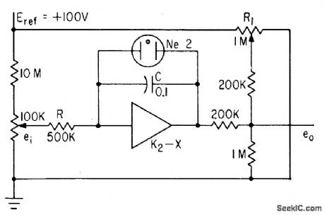
Uses operational amplifier in integrating circuit, neon lamp as automatic switch, and resistance network that allows output to be varied around level set by R1. Used to generate sweeps with high linearity up to 18 cps.-A. Angelone, Subaudio Sawtooth Generator Gives One-Percent linearity, Electronics, 34:48, p 42-43. (View)
View full Circuit Diagram | Comments | Reading(708)
RS_232_transceiver_with_automatic_power_shutdown
Published:2009/7/23 22:44:00 Author:Jessie
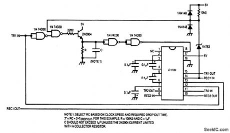
This circuit automatically shuts down when there is no data flow through the interface. A data stream on either the RS-232 or logic inputs activates the transceiver. The data must begin with a logic-1 preamble, and the data stream must contain a sufficient number of 1s to keep the transceiver active. The preamble can be as short as 50 μs. Alternatively, input to the circuit could be an RS-232 handshake signal, such as Data Set Ready (DSR) or Clear to Send (CTS), which remain high during the data transfer. The LT1180 200-μs turn-on delay does not limit the data rate in the circuit. Once the LT1180 is active, data can be processed at the maximum 100kbaud data rate. (View)
View full Circuit Diagram | Comments | Reading(692)
Thermally_controlled_NiCad_battery_charger
Published:2009/7/23 22:43:00 Author:Jessie
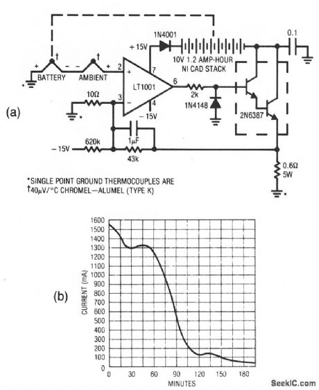
This circuituses an LT1001 and a2N3687 Darlington to form a simple charger for NiCad batteries. The batteries can be charged at a high rate without danger because the cell temperature is measured, and the charging rate is adjusted accordingly. Notice that two thermocouples are used. The battery thermocouple is mounted on one of the cells in the pack, and the ambient thermocouple is exposed to ambient temperature (mounted on a thermal mass that approximates that of the battery pack). The thermocouple voltages cancel and the positive input of the LT1001 is at zero. the temperature difference between the two thermocouples determines the input. As battery temperature rises, this small negative voltage (1°C difference between thermocouples equals 40 μV) becomes larger. The LT1001, operating at a gain of 4300, gradually reduces current through the battery to maintain a balance at the LT1001 input. The effect of this action is shown in Fig. 10-60B. The battery charges at a high rate until heating occurs and the circuit then tapers the charge. With the values shown, the battery-surface temperature rise (above ambient) is limited to the very safe level of 5°C. (View)
View full Circuit Diagram | Comments | Reading(672)
Amplifier_with_10_dB_gain_over_nine_octaves
Published:2009/7/23 23:16:00 Author:Jessie

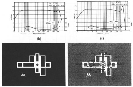
This circuit has a gain of about 10 dB from 3 MHz to over 1GHz (Fig.2-59B). The gain/VSWR versus frequency, PC-board photomaster, and parts layout are shown in Figs. 2-59C, 2-59D, and 2-59E, respectively. The actual layout dimensions are: 1.8 x 1.2 . Two type OSM215 50-Ω input and output connectors can be mounted opposite to the component side of the board, if required. (View)
View full Circuit Diagram | Comments | Reading(1007)
Simple_5_V_fixed_regulator
Published:2009/7/23 23:16:00 Author:Jessie
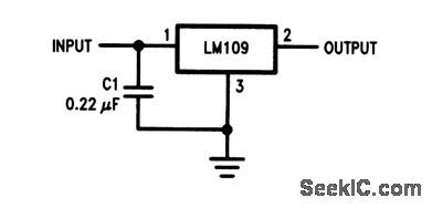
This simple circuit accepts line voltages from 7 to 35V, and produces a regulated 5-V output at 1.5A. C1 is added to prevent oscillation. (View)
View full Circuit Diagram | Comments | Reading(597)
Precision_instrumentation_amplifier
Published:2009/7/23 23:16:00 Author:Jessie
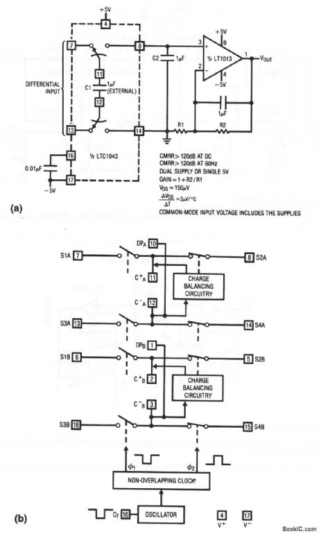
This circuit uses an LTC1043 switched-capacitor IC (Fig. 1-4B) and an LT1013 op amp to form a simple, precise instrumentation amplifier. The 0.01-μF capacitor at pin 16 sets the switching frequency at 500 Hz. (View)
View full Circuit Diagram | Comments | Reading(907)
FIVE_SILICON_TRANSISTORS_BUILD_15_MV_SIGNAL_210_V_AT_5_W
Published:2009/7/23 23:16:00 Author:Jessie
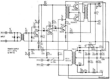
Nulling amplifier energizes control winding of servomotor for error-signal inputs of only few millivolts, using two voltage amplifiers, driver, and push-pull power output stage.-C. H. Smoot and F. J. Karlov, Boiler Control: Simple Controller for a Complex Job, Electronics, 37:18, p 88-93. (View)
View full Circuit Diagram | Comments | Reading(2218)
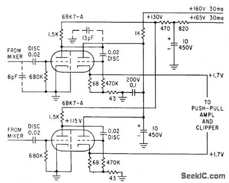
PREFERRED_VIDEO_DETECTOR
Published:2009/7/23 23:16:00 Author:Jessie
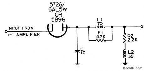
For demodulating pulse-modulated i-f signals in range between 20 and 70 Mc. Video output pulses ore negative, with 40 nsec rise time and 70 nsec fall lime.-NBS, Handbook Preferred Circuits Navy Aeronautical Electronic Equipment, Vol. 1, Electron Tube Circuits, 1963, PC 20, p 20-2. (View)
View full Circuit Diagram | Comments | Reading(705)
Peak_clipping_ac_voltage_regulator
Published:2009/7/23 23:16:00 Author:Jessie
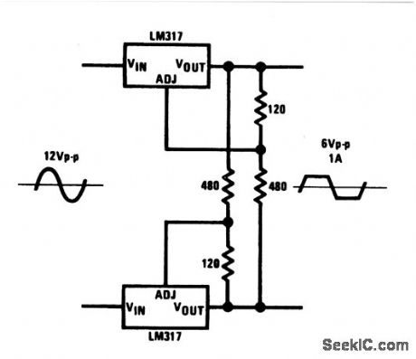
This circuit uses two linear regulators to clip a 12-Vac input signal to a precise 6 Vpp at 1 A. Symmetry of the output signal depends on precise selection of the 120/480 resistors. (View)
View full Circuit Diagram | Comments | Reading(1024)
Wide_range_V_F_converter
Published:2009/7/23 23:15:00 Author:Jessie
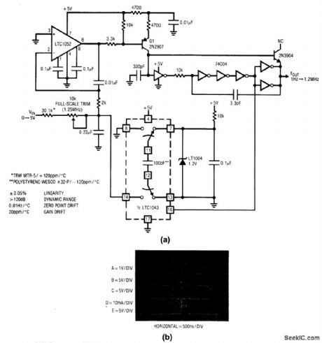
Fig. 12-3 This circuit features 1-Hz to 1.25-MHz operation with 0.05% linearity, and a typical temperature coefficient of 20 ppm/℃. Notice that in the lower frequency ranges, currents at the junction of the 330-pF capacitor and the Q1 collector are small and board leakage can cause jitter. If so, mount the capacitor, Q1, and the inverter input connection on a teflon standoff, using short connections. To trim, apply +5.000 V and adjust the 1.25-MHz trim for 1.2500-MHz Output. Linear Technology Linear Applications Handbook 1990 p AN9-13.
(View)
View full Circuit Diagram | Comments | Reading(689)
12_V_battery_charger
Published:2009/7/23 23:15:00 Author:Jessie

This circuit provides for a quick charge of 12-V gelled-electrolyte lead-acid batteries, and shuts off at full charge. The LED turns on when the battery is fully charged. (View)
View full Circuit Diagram | Comments | Reading(3365)
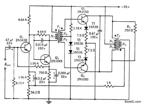
75_W_CLASS_B_SERVO_AMPLIFIER
Published:2009/7/23 23:15:00 Author:Jessie
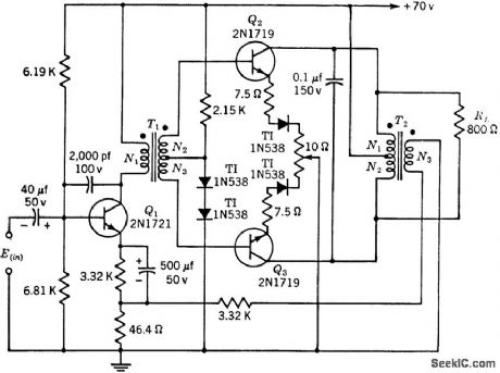
Gives power gain of 45 db. Voltage amplification is constant within 2 db of 44 db. Transformer data is for 400-cps operation.-Texas Instruments Inc., Transistor Circuit Design, McGraw-Hill, N.Y., 1963, p 242. (View)
View full Circuit Diagram | Comments | Reading(747)
RIAA_preamplifier
Published:2009/7/23 23:15:00 Author:Jessie
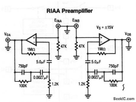
This circuit also uses both halves of an RC4995 (Fig .5-11B) (View)
View full Circuit Diagram | Comments | Reading(0)
PARTIAL_ADDING_MIXER
Published:2009/7/23 23:14:00 Author:Jessie
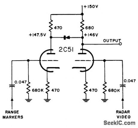
Semiconductor diode connected between plates in nonconducting direction, with 1.5 v back voltage, reduces additive factor of common-plate mixer. Marker input must have sufficient amplitude to overcome diode back-bias before marker signal can appear at output. Positive radar video at input appears as negative output. At coincidence, radar video biases diode to extent that only small amount of marker pulse can pass and add to radar video.-NBS, Handbook Preferred Circuits Navy Aeronautical Electronic Equipment, Val. 1, Electron Tube Circuits, 1963, p N4-9. (View)
View full Circuit Diagram | Comments | Reading(695)
40__to_900_MHz_broadband_amplifier
Published:2009/7/23 23:14:00 Author:Jessie
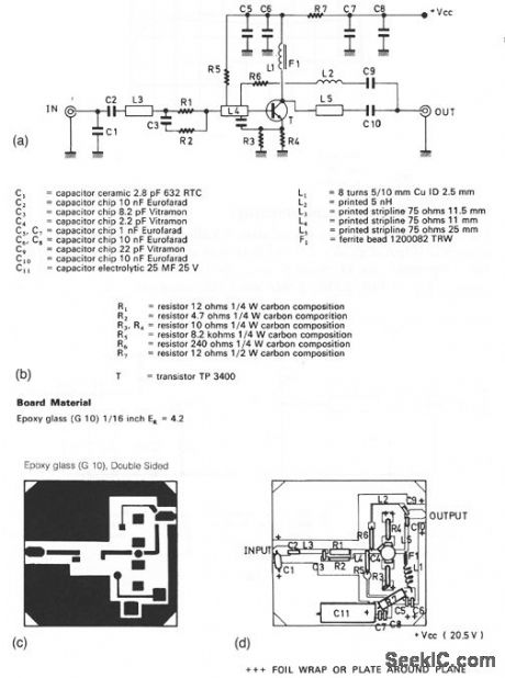
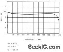
This circuit has a gain of about 9.5 dB over the frequency range, and delivers an output of about 1.2 V into 75Ω, with an IMD level of about -60 dB.The components lists, PC-board photomaster, components layout, and gain are shown in Figs. 2-58B, 2-58C, 2-58D, and 2-58E, respectively. (View)
View full Circuit Diagram | Comments | Reading(754)
10_W_CLASS_B_SERVO_AMPLIFIER
Published:2009/7/23 23:32:00 Author:Jessie
Gives power gain of 39 db. Voltage amplification is constant within 1 db of 32.5 db. Transformer data is for 400-cps operation. -Texas Instruments Inc., Transistor Circuit Design, McGraw-Hill, N.Y., 1963, p 243. (View)
View full Circuit Diagram | Comments | Reading(793)
VIDEO_PREAMP
Published:2009/7/23 23:32:00 Author:Jessie
Accepts output of balanced mixer of microwave interferometer system. Bandwidth is 3 Mc.-H. L. Bunn, Determining Electron Density and Distribution in Plasmas, Electronics, 34:14, p 71-75. (View)
View full Circuit Diagram | Comments | Reading(2588)
Quartz_stabilized_V_F_converter
Published:2009/7/23 23:31:00 Author:Jessie
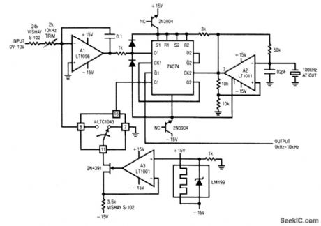
Fig. 12-9 This circuit does not require an external clock (as does the circuit of Fig. 12-6) but uses a 100-kHz crystal to provide 0.005% linearity with 5 ppm/℃ drift, and a range of 1 Hz to 10 kHz. To trim, apply 10.000 V and adjust the 10-kHz trim for 10.000 kHz. Linear Technology Linear Applications Handbook, 1990 p AN14-6. (View)
View full Circuit Diagram | Comments | Reading(721)
_5_A_positive_adjustable_voltage_regulator
Published:2009/7/23 23:31:00 Author:Jessie
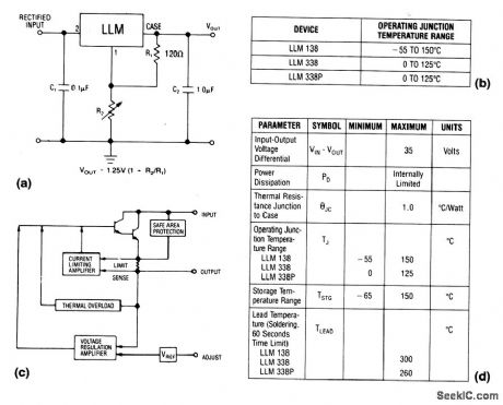
The LLM is a three-terminal adjustable regulator IC with an output range from +1.2 to +32V, with the output voltage set by two external resistors. Because the regulator is floating, higher output voltages can be obtained as long as the maximum input-output voltage differential is not exceeded. Characteristics are shown in Fig. 7-36B, 7-36C, and 7-36D. (View)
View full Circuit Diagram | Comments | Reading(708)
SYNCHRONOUS_FILTER_FOR_ADF
Published:2009/7/23 23:31:00 Author:Jessie
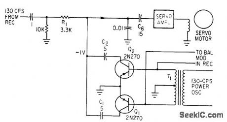
Separates 130-cps motor drive voltage from voice frequencies in output of adf receiver-P. V. Sparks, Servo Filter and Gain Control Improve Automatic Direction Finder, Electronics, 34:23, p 110-113. (View)
View full Circuit Diagram | Comments | Reading(1815)
| Pages:1106/2234 At 2011011102110311041105110611071108110911101111111211131114111511161117111811191120Under 20 |
Circuit Categories
power supply circuit
Amplifier Circuit
Basic Circuit
LED and Light Circuit
Sensor Circuit
Signal Processing
Electrical Equipment Circuit
Control Circuit
Remote Control Circuit
A/D-D/A Converter Circuit
Audio Circuit
Measuring and Test Circuit
Communication Circuit
Computer-Related Circuit
555 Circuit
Automotive Circuit
Repairing Circuit