
Circuit Diagram
Index 1103
Data_acquisition_IC_with_4_wire_microprocessor_interface
Published:2009/7/23 22:24:00 Author:Jessie
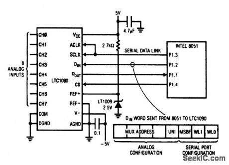
This circuit shows the basic interface connections between an 8-input LTC1090 data-acquisition IC and an Intel 8051 microprocessor.The 4-wlre serial interface includes chip-select CS, shift clock SCLK for synchronizing data bits, a data input DIN and a data output, DOUT. Data bits are transmitted and received simultaneously (full duplex), minimizing the transfer time. The external ACLK input controls the conversion rate, and can be tied to the SCLK, as shown, or can be derived from the system clock (the 8051 ALE pin), or it can be run asynchronously. When the ACLK pin is driven at 2 MHz, the conversion time is 22 μs. Consult the LTC1090 datasheet for further data. (View)
View full Circuit Diagram | Comments | Reading(1116)
Negative_variable_voltage_reference_VSUBOUT_SUB_lower_than_reference_zener
Published:2009/7/23 22:24:00 Author:Jessie
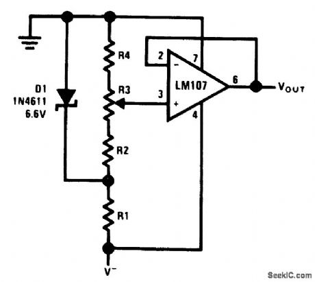
This circuit is similar to that of Fig.10-47,except that a variable negative-voltage reference is provided for VOUT . (View)
View full Circuit Diagram | Comments | Reading(669)
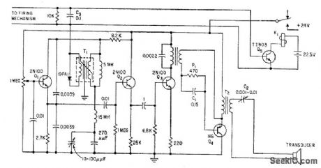
900_KC_FLAW_DETECTOR
Published:2009/7/23 22:24:00 Author:Jessie
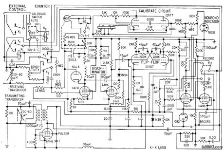
Attenuation of ultrasonic pulses boomed through test piece reveals presence and extent of internal defects, such as nonbonds between aluminum cladding and uranium core. Test piece and transducers are submerged in water to provide good coupling for 900-kc ultrasonic wave from barium titanate transducer of pulser. Motor sets discriminator threshold to equal signal received from attenuator.-J. D. Ross and R. W. Leep, Ultrasonic Pulses Detect Reactor-Slug Flaws, Electronics, 31:25, p 59-61. (View)
View full Circuit Diagram | Comments | Reading(1220)
SOLID_STATE_TIMER
Published:2009/7/23 22:24:00 Author:Jessie
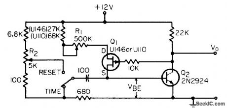
Uses fet constant-current source to eliminate timing errors due to unregulated power supplies and line transients. Range of 0.1 to 50 sec is con trolled by R2.-J. Geekie, Simple Fet Timer, EEE, 14:3, p 62. (View)
View full Circuit Diagram | Comments | Reading(826)
900_MHz_gain_controlled_amplifier
Published:2009/7/23 22:24:00 Author:Jessie
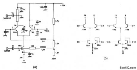
This circuit shows an SL2365 transistor array connected as a gain-controlled amplifier. The transistor-array connections are shown in Fig. 2-35B.The collector load of TR1 is a transformer that is composed of a 14-mm length of 75-Ω stripline resonated with a 1- to 6-pF variable capacitor. The transformer secondary is a small loop of stiff wire that is grounded at one end and located a few mm above the stripline. The noise figure at full gain is 9 dB. (View)
View full Circuit Diagram | Comments | Reading(1091)
LINEAR_SAWTOOTH
Published:2009/7/23 22:34:00 Author:Jessie
Q1 and 02 in emitter-coupled mvbr and constant-current generator Q3 produce sweep having linearity comparable to that of vacuum-tube circuits.-B. Rakovic, One More Transistor Makes a Linear Sawtooth, Electronics, 35:49, p 50-51. (View)
View full Circuit Diagram | Comments | Reading(1011)
STROBE_GENERATOR
Published:2009/7/23 22:33:00 Author:Jessie
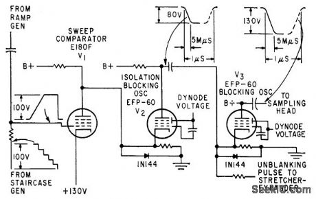
Sweep comparator V1 mixes output of ramp generator and staircase generator to give sampling or strobe pulse. Instantaneous d-c level of ramp, cor responding to a step, fixes time at which strobe signal is generated.-W. E. Bushor, Sample Method Displays Millimicrosecond Pulses, Electronics, 32:31, p 69-71. (View)
View full Circuit Diagram | Comments | Reading(722)
SONAR_PEAK_AMPLITUDE_DETECTOR
Published:2009/7/23 22:33:00 Author:Jessie
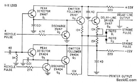
Reshapes pulses from playback amplifiers handling pulse-amplitude-modulation timedivision multiplex signals recorded and reproduced in magnetic-tape storage system, to provide narrow 2-microsec pulses coinciding with reference playback dock and having amplitude proportional to peak amplitude of input pulse sample. Used in training sonar operators at land-based sonar.-M. H. Damon, Jr., Tape Target Classifier Trains Sonar Operators, Electronics, 33:13, p 65-69. (View)
View full Circuit Diagram | Comments | Reading(798)
Programmable_power_supply_negative_output
Published:2009/7/23 22:33:00 Author:Jessie

This circuit is similar to that of Fig. 6-62, except that the output is are shown in Fig. 6-63. To calibrate, apply 0111 to TTL latch, and adjust P1 for 5.200-V output. (View)
View full Circuit Diagram | Comments | Reading(604)
DUAL_OUTPUT_FREE_RUNNING_TIMER
Published:2009/7/23 22:33:00 Author:Jessie
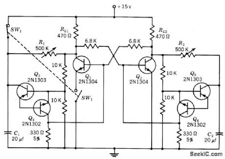
Each output may be controlled separately. With stable power-supply voltage and constant ambient temperature, accuracy of 0.1% may be expected with this type of repeating timer. Switch is shown in off position, Load resistors RL1 and RL2 can be replaced with 500-ohm relay coil shunted by 1N2069 diode. -Texas Instruments Inc., Transistor Circuit Design, McGraw-Hill, N.Y., 1963, p 414. (View)
View full Circuit Diagram | Comments | Reading(775)
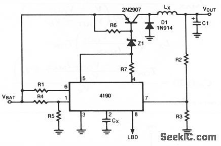
Battery_life_extender
Published:2009/7/23 22:33:00 Author:Jessie
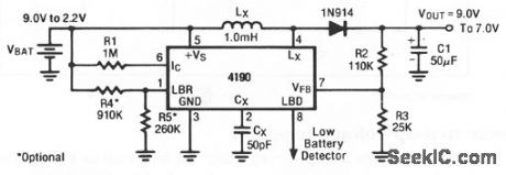
This circuit extends the lifetime of a 9-V battery. The regulator remains in a quiescent state (drawing only 215 μA) until the battery voltage decays below 7.5 , at which time the circuit starts to switch and regulate the output at 7.0 V until the battery falls below 2.2 V. If this circuit is operated at a typical 80% efficiency with an output current of 10 mA, at 5.0-V battery voltage, the average input current is 17.5 mA. (View)
View full Circuit Diagram | Comments | Reading(0)
TKIANULES
Published:2009/7/23 22:32:00 Author:Jessie
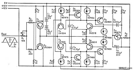
Peaks, slopes, and frequency of triangular waves can be varied independently. R10-R11 control positive slope, R11-R15 negative slope, and C1-C2 both slopes. Zener voltages of D1-D2 determine peaks.-R. Zane, Triangle Generator Adjusts Output Slopes and Peaks, Electronics, 38:12, p 85-86. (View)
View full Circuit Diagram | Comments | Reading(620)
Variable_gain_differential_input_instrumentation_amplifier
Published:2009/7/23 22:32:00 Author:Jessie
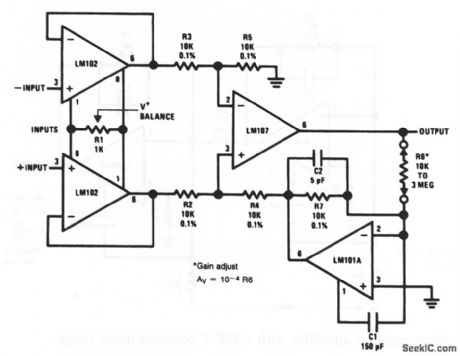
The gain of this instrumentation amplifier can be set by selecting R6. The amplifier can be balanced by adjusting R1. (View)
View full Circuit Diagram | Comments | Reading(0)
60_KC_UNDERWATER_TRANSMITTER
Published:2009/7/23 22:32:00 Author:Jessie
Consists of oscillator, buffer, driver, and power amplifier feeding barium titanate projector. Bandwidth is 1 kc in 60-kc region. Used to monitor underwater mine operation as test ships pass over. Receiving hydrophone on bottom may be up to 600 feet away. When mine senses approach of target, relay K1 is activated, turning on transmitter.-M. J. Aucremanne and D. D. Woolston, Telemeter System Relays Undersea Ordnance Data, Electronics, 31 :41, p 84-87. (View)
View full Circuit Diagram | Comments | Reading(771)
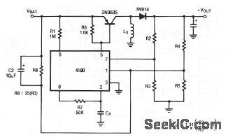
Step_down_voltage_regulator_for_inputs_greater_than_30_V
Published:2009/7/23 22:32:00 Author:Jessie
Component values are tailored to circuit requirements as described for Fig. 4-2. Adding the zener allows battery voltage to increase by the zener value. For example, if a 24-V zener is used, maximum battery voltage can go to 48 V.However, addition of the zener does not alter the maximum charge of supply. With a 24-V zener, the circuit stops when battery voltage drops below 24 V + 2.2 V= 26.2V. (View)
View full Circuit Diagram | Comments | Reading(732)
Programmable_power_supply
Published:2009/7/23 22:32:00 Author:Jessie
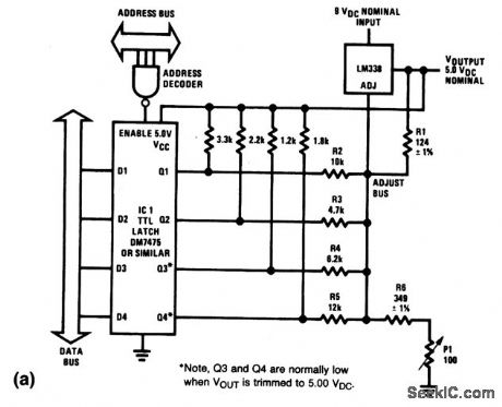
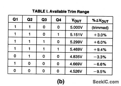
The output of this 5-V digital supply can be trimmed above and below 5-V with digital-logic signals applied to IC1. The exact values for various combinations of logic signals are given in Fig. 6-62B. To calibrate, apply 1100 to IC1, and adjust P1 for 5.000-V output. (View)
View full Circuit Diagram | Comments | Reading(1850)
SYNCHRONOUS_SWEEP
Published:2009/7/23 22:31:00 Author:Jessie
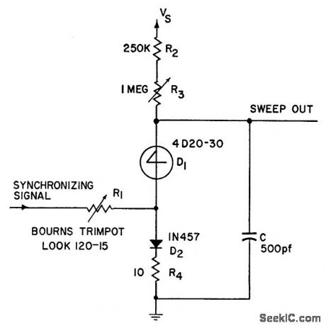
Produces linear 20-V sawtooth with four-layer diode and six other components. Maximum sweep role can reach 100 kc. Provides synchronous operation with good linearity and sufficiently Inst retrace to eliminate need for blanking in oscilloscope applications.-4-Layer Diode Sweep (Synchronous), Electronic Circuit Design Handbook, Mactier Pub. Corp., N.Y., 1965, p 173. (View)
View full Circuit Diagram | Comments | Reading(696)
CURRENT_MODE_SWITCH
Published:2009/7/23 22:39:00 Author:Jessie

With l,000-Mc lime base applied to base of Q2, two current. mode switches together serve to give ac curacy of 0.5 nsec in measurement of time intervals with quinary scaler.-R. Englemann, Quinary Scalers: Measure Time Intervals Digitally, Electronics, 37:5, p 34-36. (View)
View full Circuit Diagram | Comments | Reading(744)
Step_down_regulator_with_short_circuit_protection
Published:2009/7/23 22:39:00 Author:Jessie
With this circuit, the low-battery detector (LBD) is connected to sense the output voltage, and shuts off the oscillator by forcing pin 2 low if the output voltage drops. Component values are tailored to circuit requirements, as described in Fig. 4-2, except: choose resistor values so that R5= R3 and R4= R2, and make R8 25 to 35 times higher than R3. (View)
View full Circuit Diagram | Comments | Reading(662)
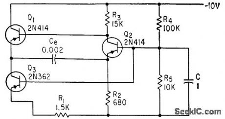
INTERVAL_TIMER
Published:2009/7/23 22:38:00 Author:Jessie
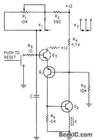
Interval is determined by C, which can be paralleled capacitors to in. crease range.-N. C. Hekimian, PNP-NPN CIRCUITS; New Look at a Familiar Connection, Electronics, 35:47, p 42-46. (View)
View full Circuit Diagram | Comments | Reading(702)
| Pages:1103/2234 At 2011011102110311041105110611071108110911101111111211131114111511161117111811191120Under 20 |
Circuit Categories
power supply circuit
Amplifier Circuit
Basic Circuit
LED and Light Circuit
Sensor Circuit
Signal Processing
Electrical Equipment Circuit
Control Circuit
Remote Control Circuit
A/D-D/A Converter Circuit
Audio Circuit
Measuring and Test Circuit
Communication Circuit
Computer-Related Circuit
555 Circuit
Automotive Circuit
Repairing Circuit