
Signal Processing
Index 101
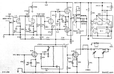
PUSH_PULL_OUTPUT_WITH_LATTICE_FILTERS
Published:2009/7/21 7:39:00 Author:Jessie
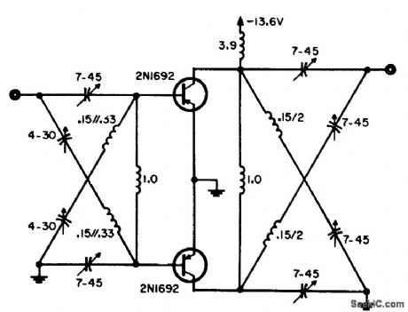
Preferred for frequencies above 30 Mc because lattice arrangement without transformers is much easier to construct and align than standard push-pull circuit.-W. A. Rheinfelder, Choosing the Best Transmitter Output Stage, EEE, 11:10, p 48-53. (View)
View full Circuit Diagram | Comments | Reading(698)
MINIATURE_F_M_TRANSMITTER
Published:2009/7/21 7:38:00 Author:Jessie
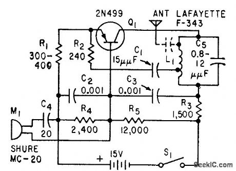
Single 2N499 transistor performs functions of r-f oscillator, frequency modulator, and audio amplifier for tiny portable transmitter having range of 200 feet. Suitable for use with public-address system.-D. E. Thomas and J. M. Klein, How to Construct a Miniature F.M Transmitter, Electronics, 32:31, p 80-81. (View)
View full Circuit Diagram | Comments | Reading(1151)
STANDARD_PARALLEL_TRANSISTOR_OUTPUT_DOUBLER
Published:2009/7/21 7:01:00 Author:Jessie
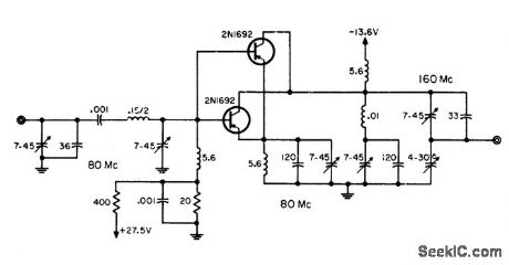
Input is tuned to 80 Mc and output to 160 Mc. Parallel tuned circuit with built-in trap is required in output circuit to suppress 80-Mc fundamental. Conversion power gain is 6 db. Maximum power is 650 mw.-W. A. Rheinfelder, Choosing the Best Transmitter Output Stage, EEE, 11:10, p 48-53. (View)
View full Circuit Diagram | Comments | Reading(825)
SILICON_TRANSISTORS_MINIMIZE_POWER_DRAIN
Published:2009/7/21 6:32:00 Author:Jessie
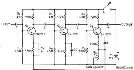
Used in conjunction with high-value circuit resistances to permit operation of preamplifier with battery drain of less than 1 nw. Gain is 100 for bandwidth of 18 kc. Intended primarily for use at room temperature.-C. D. Todd, Preamplifier Designed for Minimum Power Consumption, Electronics, 33:18, p 106-107. (View)
View full Circuit Diagram | Comments | Reading(717)
F_M_WIRELESS_MICROPHONE
Published:2009/7/21 7:28:00 Author:Jessie
Transmitter has range of 200 yards when used with sensitive commercial receiver covering 96-110 Mc. Transistor stage frequency-modulates tunnel-diode oscillator, - Transistor Manual, Seventh Edition, General Electric Co., 1964, p 357. (View)
View full Circuit Diagram | Comments | Reading(1308)
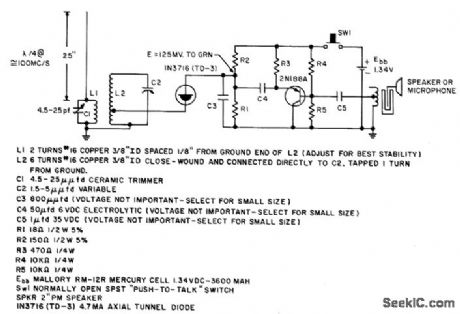
460_KC_F_M_WIRELESS_MICROPHONE
Published:2009/7/21 7:27:00 Author:Jessie
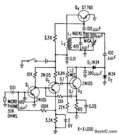
Radiates about 0.2 micromicrowatt directly from tank circuit to establish induction field within usable area of auditorium stage without exceeding FCC radiation field limitation. Normal speaking voice produces peak f-m deviation of about 10 kc.-G. F. Montgomery, Wireless Microphone Uses F-M Modulation, Electronics, 31:1, p 54-55. (View)
View full Circuit Diagram | Comments | Reading(1129)
9_KC_OSCILLATOR_STABILIZER
Published:2009/7/21 7:25:00 Author:Jessie

Insures 24 w output over temperature range of -20 to +120°F. Zener diode voltage-regulating circuit prevents changes in collector supply voltage of oscillator Q1. Base-driven modulator Q2 may be fed from tape repeater preamp, microphone, or master control center serving induction radio system using roadside telephone-line loops.-E. A. Hanysz, J. E. Stevens, and A. Meduvsky, Communication System for Highway Traffic Control, Electronics, 33:42, p 81-83. (View)
View full Circuit Diagram | Comments | Reading(743)
SSB_EXCITER
Published:2009/7/21 7:23:00 Author:Jessie
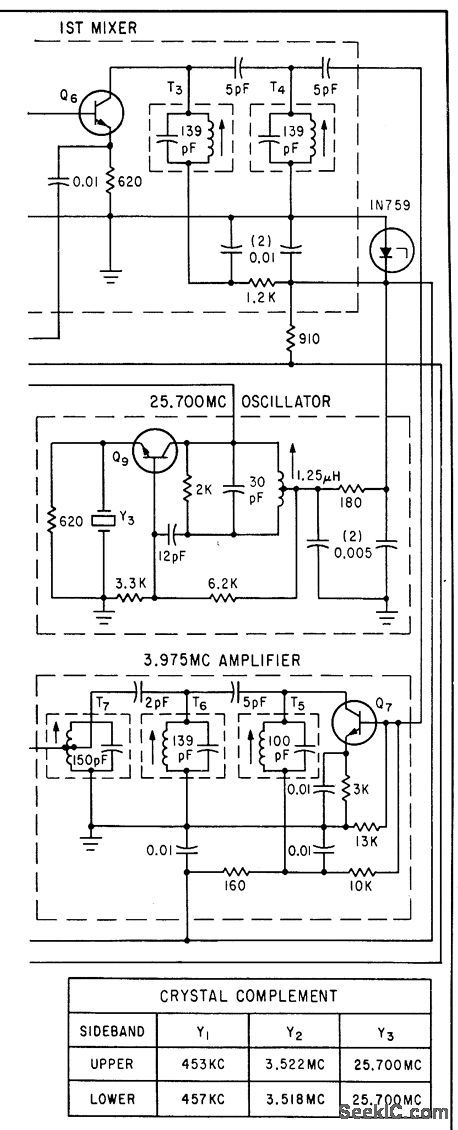
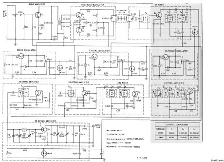
Silicon transistors reduce noise and increase reliability of single-side band exciters. Circuit shown, for 10-meter band, gives choice of upper or lower sideband.-D. L. Wilcox, Single-Sideband Exciter uses Planar Silicon Transistors, Electronics, 35:32, p 65-67. (View)
View full Circuit Diagram | Comments | Reading(1255)
LOW_POWER_VFO_C_W_80_METER_TRANSMITTER
Published:2009/7/21 7:21:00 Author:Jessie
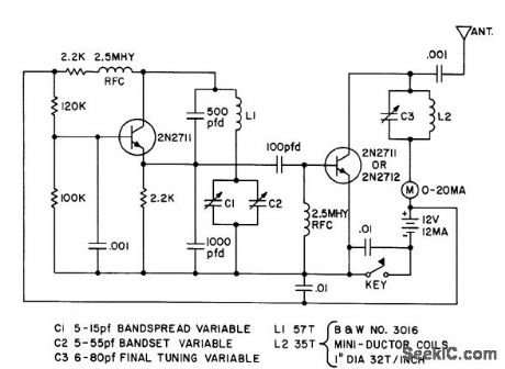
Power output is 100 mw in amateur band.- Transistor Manual, Seventh Edition, General Electric Co., 1964, p 386. (View)
View full Circuit Diagram | Comments | Reading(839)
LOW_POWER_BROADCAST_BAND_TRANSMITTER
Published:2009/7/21 7:20:00 Author:Jessie
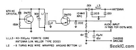
Crystal-controlled 670-kc oscillator and single-transistor amplifier stage provide 400 microwatts a-m for antenna.- Transistor Manual, Seventh Edition, General Electric Co., 1964, p 386. (View)
View full Circuit Diagram | Comments | Reading(930)
1_W_AT_50_MC
Published:2009/7/21 7:34:00 Author:Jessie
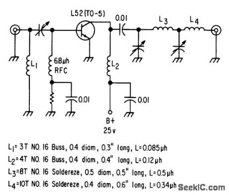
Relatively high breakdown voltage of L52 transistor permits amplitude modulation. Overall efficiency is 65%. Combination pi-L network matches common emitter class-C stage to 50-ohm antenna.-Texas Instruments Inc., Solid-State Communications, McGraw-Hill, N.Y., 1966, p 322. (View)
View full Circuit Diagram | Comments | Reading(674)
F_M_WIRELESS_MIKE
Published:2009/7/21 7:33:00 Author:Jessie
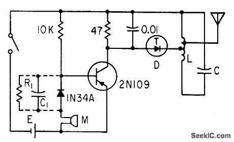
Oscillator. modulator using single tunnel diode produces 35-kc frequency deviation per my of modulating signal at 90 Mc. When fed by dynamic mike, range is up to 100 feet. If pre-emphasis is desired, diode 1N34A may be replaced by R1-C1 circuit shown in dotted lines, having time constant of 75 microsec.-W. Ko, Tunnel Diode F.M Wireless Microphone, Electronics, 33:47, p 93-95. (View)
View full Circuit Diagram | Comments | Reading(2224)
CARRIER_SUPPRESSION
Published:2009/7/21 7:32:00 Author:Jessie
Suppressed-carrier modulation improves efficiency of medium-power transmitter and provides noise advantages of exalted-carrier detection in receiver.-J. Dysinger, W. Whyland, and R. Wood, New Suppressed-Carrier Modulation Technique, Electronics,33:6, p 47-49. (View)
View full Circuit Diagram | Comments | Reading(836)
VOICE_OPERATED_CONTROL_WITH_DAMPING
Published:2009/7/21 7:31:00 Author:Jessie
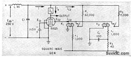
Relays provide timed sequential switching of pentode load to IC. filtered power supply when operator speaks into microphone, there by preventing over shoot.-E. L. Harris and O. J. M. Smith, Novel Circuit Damps Transients in Voice-operated Transmitters, Electronics, 35:39, p 66-67. (View)
View full Circuit Diagram | Comments | Reading(714)
PAGING_TRANSMITTER
Published:2009/7/21 7:30:00 Author:Jessie
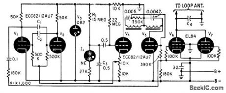
Feeds single-wire loop surrounding area to be covered. Multivibrator V1-V2 produces carrier frequencies in range from 15 to 30 kc, keyed on and off at various repetition rates in range from 1/50th to 1/200th second, for selective paging of up to 45 different receivers.-J. G. DeGraaf, Selective Paging System Uses Coded Transmission, Electronics, 33:9, p 68-70. (View)
View full Circuit Diagram | Comments | Reading(723)
223_MC_TELEMETRY_TRANSMIITER
Published:2009/7/21 7:28:00 Author:Jessie
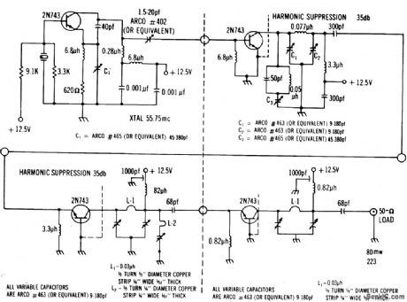
Crystal-controlled Colpitts delivers 10 mw to first doubler. Second doubler has trap to eliminate 11.5-Mc fundamental. Power output to final is about 45 mw at 223 Mc. Class C final delivers 100 mw to 50-ohm load.-Texas Instruments Inc., Solid-State Communications, McGraw-Hill, N.Y., 1966, p 326. (View)
View full Circuit Diagram | Comments | Reading(710)
SIMPLE_TOUCHTONESUPTM_SUP_GENERATOR
Published:2009/7/7 21:29:00 Author:May
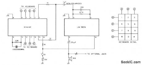
The oscillator is a Motorola MC14410CP chip using a 1-MHz crystal. The chip generates both the high and low tones, feeding the energy to the amplifier through 1-K resistors and the 1-μF capacitor. Values for the output resistors can vary from a few hundred Ω to about 60 KΩ. The value of the resistor shunting the crystal can vary from about 3 to 15 MΩ. The amplifier consists of an LM-380N. (View)
View full Circuit Diagram | Comments | Reading(776)
LIGHT_SENSITIVE_AUDIO_OSCILLATOR
Published:2009/7/7 21:21:00 Author:May
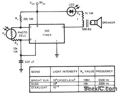
This circuit's frequency of oscillation increases directly with light intensity. The greater the light intensity, the higher the frequency of the oscillator. The 555 timer operates in the astable oscillator mode where frequency and duty cycle are controlled by two resistors and one capacitor. The capacitor charges through R1 and R2, and discharges through R2, a standard photo cell. Resistor R3 limits the upper frequency of oscillation to the audio range. The lower range of approximately 1 pps is set 'oy the value of R2, approximately 10-MΩ, with the photo cell almost totally dark.A loudspeaker provides audio output, and an LED is used as a pilot light that flashes when the frequency falls below about 10 to 12 Hz. Extremely sensitive, especially on the dark end of the photocell resistance range, the unit can detect lightning many miles away, providing a rapid frequency increase with each flash of lightning. When used with a flashlight at night, the device becomes a simple optical radar for the blind, showing angular direction to a light-reflecting object, as well as height and distance to the object when hand scanned back and forth.This light-sensitive audio oscillator can also serve as an audible horizontal level device by noting the position of a liquid bubble illuminated by a light source. Thus, you can sense fluid levels as well as the vibration state of a fluid surface level. (View)
View full Circuit Diagram | Comments | Reading(1038)
OSCILLATOR_FOR_CHANNELS_2_6
Published:2009/7/7 20:56:00 Author:May
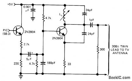
Transmitter serving as interface between video game and TV set can be tuned with L1 to vacant chan, nol in low TV band. Regular antenna should be disconnected when output of oscillator is fed to TV set via twin-line, to avoid broadcasting game signals. L1 is 4tums No. 18 spaced 3/8 inch on 1/4-inch slug-tuned form.-B. Matteson, King Pong Game Offers Hockey and Tennis Alternatives to TV Re-Runs, EDN Magazine, Aug. 5, 1975, p 47-55. (View)
View full Circuit Diagram | Comments | Reading(865)
40_W_AT_50_MC
Published:2009/7/21 7:50:00 Author:Jessie

Can be used with phase-modulated oscillator as drive source or with crystal oscillator for straight cw operation. Grounded emitter tonus m driver Q3 and power amplifier should be as short as possible to prevent degeneration.-R. Brubaker, A Solid-State Transmitter with 40 Watts Output at 50 MHz, Motorola Application Note AN-172, Dec. 1965. (View)
View full Circuit Diagram | Comments | Reading(865)
| Pages:101/195 At 20101102103104105106107108109110111112113114115116117118119120Under 20 |
Circuit Categories
power supply circuit
Amplifier Circuit
Basic Circuit
LED and Light Circuit
Sensor Circuit
Signal Processing
Electrical Equipment Circuit
Control Circuit
Remote Control Circuit
A/D-D/A Converter Circuit
Audio Circuit
Measuring and Test Circuit
Communication Circuit
Computer-Related Circuit
555 Circuit
Automotive Circuit
Repairing Circuit