
Signal Processing
Index 114
UNDERSEA_PROPAGATION_RECEIVER
Published:2009/7/23 22:06:00 Author:Jessie
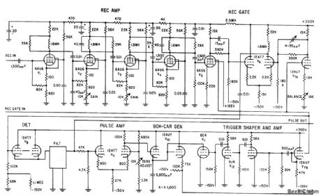
Amplified output of receiving transducer is fed to receiver gate that acts like switch in that output appears only when pulse is applied. Receiver is thus sensitive only for short intervals of time in which return is expected. Output of receiver gate is detected by V8 and filtered to get pulse envelope for crt. Receiver pulse is also amplified by V9 and used to charge capacitor in boxcar generator, so amplitude of pulse is remembered in interval between pulses. To make boxcar generator forget old amplitude when another pulse arrives, receiver gate is shaped into narrow pulse used to discharge capacitors through V11 just before arrival of next pulse.-W. C. Gore, Ultrasonics Tests Undersea Propagation, Electronics, 31:35, p 32-35. (View)
View full Circuit Diagram | Comments | Reading(830)
TRANSISTOR_MEASUREMENTS_AT_100_MC
Published:2009/7/23 22:06:00 Author:Jessie
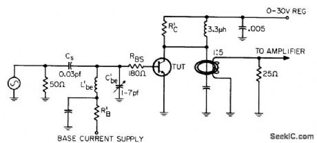
Used to measure h-fe at 100 Mc, where all circuit parameters become more significant and make accurate measurements difficult. Circuit has provisions for separating measured signal from noise, high-gain pre-meter amplifier, and accurate method of metering r-f level. Maximum error is under 5%.-W. H. Hamlin, How to Measure h-fe et 100 mHz, EEE, 13:6, p 70-72. (View)
View full Circuit Diagram | Comments | Reading(642)
SSB_generator
Published:2009/7/23 22:05:00 Author:Jessie
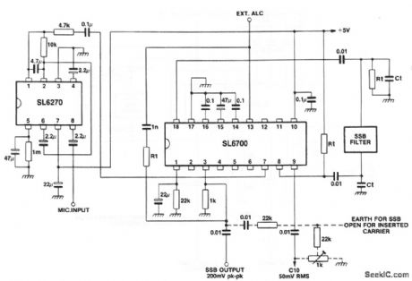
This circuit shows an SL6700 (Fig. 2-13) connected to form a no-adjustment SSB generator. The trim adjustment shown in dashed lines is only used for re-inserting a carrier (not required for basic SSB operation). Notice that the microphone input is applied through an SL6720 (Fig. 1-7). (View)
View full Circuit Diagram | Comments | Reading(2157)
SING_AROUND_TRIGGER_GENERATOR
Published:2009/7/23 22:05:00 Author:Jessie
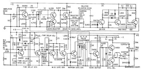
Electrical echo signals generated by receiving transducer pass through 10-Mc tuned amplifier to trigger generator that delays selected detected echo and combines it with undetected echo in fast series-transistor coincidence circuit to obtain trigger output pulse for transmitter of ultrasonic velocity measuring system.-R. L. Forgacs, Precision Ultrasonic Velocity Measurements, Electronics, 33:47, p 98-100. (View)
View full Circuit Diagram | Comments | Reading(1222)
FM_demodulator
Published:2009/7/23 22:12:00 Author:Jessie
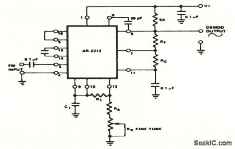
This circuit shows a precision PLL connected as an FM demodulator.The circuit can be tailored to any FM demodulation application by a choice of external components. For example, to demodulate an FM signal with a 67-kHz carrier and ±5 kHz deviation, use the following components: CO=746 pF,R1= 89.4 kΩ, C1=186 pF, RF=100 kΩ, and RC=80.6 kΩ, RO=20 kΩ. Use an 18-kΩ fixed resistor and a 5-kΩ potentiometer for RO and RX. Fine tune the circuit with RX. (View)
View full Circuit Diagram | Comments | Reading(3)
STABILIZED_SINE_WAVE
Published:2009/7/5 21:09:00 Author:May
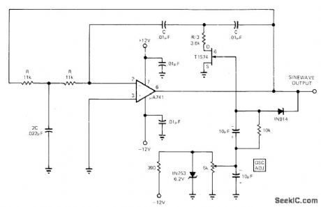
Peak detector is used with FET operated in voltage variable.-resistance mode. in combination with standard double-integration circuit having regenerative feedback. to give 1.46-kHz sinewave output into 500-ohm load at 10 V P-P. Will operate at power supply voltages off 8 to 18 V whhout appreciable variation in output amplitude or frequency. Output varies less than 1.5% in frequency and 6% in amplitude over temperature range of 10 to 65°c. Circuit can be modified for other frequencies.-F. Macli. FET Stabilizes Sine-Wave Oscillator. EDN Magazine. June 5.1973. p 87. (View)
View full Circuit Diagram | Comments | Reading(794)
VARIABLE_SLOPE_RAMP_GENERATOR
Published:2009/7/23 22:58:00 Author:Jessie
Slope is determined by rate at which C1 is charged by constant-current generator Q1-R4 through Q2. Peak of ramp is determined by R19. Circuit will synchronize over 3:1 frequency range centered on 70 kc.-D. J. Grover, Capacitor Charging Controls Variable Ramp Generator, Electronics, 39:11, p 91-92. (View)
View full Circuit Diagram | Comments | Reading(1712)
One_shot_multivibrator_with_input_lockout
Published:2009/7/23 22:56:00 Author:Jessie
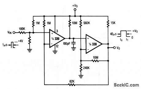
The input threshold of this comparator IC circuit is set by the resistance from the input to ground. This resistance combines with the series 100-kΩ resistor to form an input lockout. For example, if the input-to-ground resistance is also 100 kΩ, the multivibrator remains off until the input exceeds +8 V. Raytheon Linear Integrated Circuts, 1989, p. 5-30. (View)
View full Circuit Diagram | Comments | Reading(1034)
FET_RAMP_GENERATOR
Published:2009/7/23 22:56:00 Author:Jessie
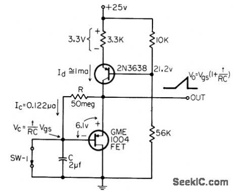
Use of mos let gives very slow rate-of-rise linear ramp generator (less than 0.1 V/sec). Longer durations can be obtained by using larger values for R and C.-J. M. Phalan, MOS FETs Give Long Time, Constant Ramps, EEE, 14:4, p 46. (View)
View full Circuit Diagram | Comments | Reading(889)
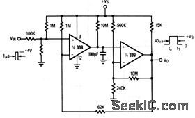
234_kHz_SINE_WAVE
Published:2009/7/5 20:56:00 Author:May
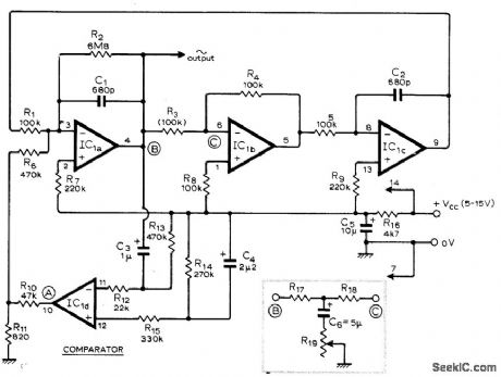
Uses low-cost LM3900N quad differential amplifier IC in lowdistortion oscillator for which third harmonic distortion is typically 0.5%. Peak-to-peak amplitude of sine-wave output is typically 25% of source voltage VCC. Frequency can be changed by altering single component. R3. or by inserting between points B and C an RC network and pot connected as shown in inset. Article gives design equations for frequency and Q.-T. J. Rossiter. Sine Oscillator Uses C.D.A. Wireless World. April 1975. p 176. (View)
View full Circuit Diagram | Comments | Reading(1167)
FREE_RUNNING_HIGH_VOLTAGE_SAWTOOTH_GENERATOR
Published:2009/7/23 22:56:00 Author:Jessie
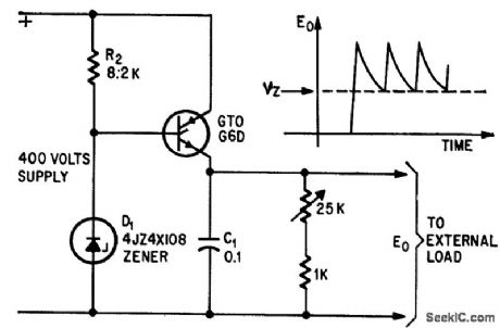
When power is applied, gale-turnoff scr triggers and applies 400 V to C1.When voltage across C1 rises above avelanche voltage of D1, GTO turns off and C1 discharges until scr conducts again.-D. R. Grafham, Now the Gate Turnoff Switch Speeds Up D-C Switching, Electronics, 37:12, p 64-71. (View)
View full Circuit Diagram | Comments | Reading(1491)
Triangle_square_wave_generator
Published:2009/7/23 22:55:00 Author:Jessie
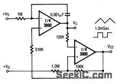
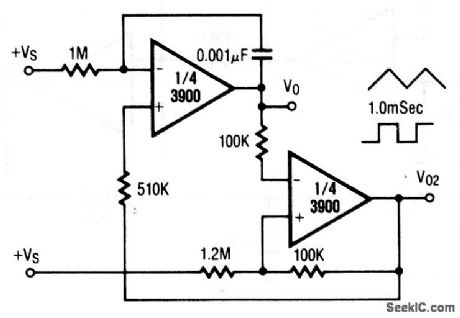
This circuit uses two sections of 3900 op amp. The duration of the triangle-(V0) and square-wave (V02) is 1.0 mS with the values shown. Raytheon Linear Integrated Circuts, 1989, p. 4-273. (View)
View full Circuit Diagram | Comments | Reading(1067)
LINEAR_RAMP_GENERATOR
Published:2009/7/23 22:55:00 Author:Jessie

Used in tester that shows computer memory performance under marginal drive currents by plotting shmoo curves. System uses two generators that differ only in component values in table. R3 in X drive circuit makes X generator lump when capacitor stops charging and starts discharging. Charging current is positive or negative depending on input voltage polarity. Npn transistors are 2N706, pnp transistors are 2N1132, and diodes are 1N921.-J. E. Gersbach, The Great Shmoo Plot: Testing Memories Automatically, Electronics, 39:15, p 127-134. (View)
View full Circuit Diagram | Comments | Reading(0)
CB_SQUELCH
Published:2009/7/23 22:52:00 Author:Jessie
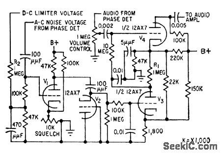
Actuated by d-c limiter voltage and ac noise voltage. With no signal, out put of noise amplifier V1 is converted into positive voltage by noise rectifier of V2 and applied to grid of squelch control lube V3, making it conduct and drive grid of V4 more negative, to squelch noise.-L. G. Sands, Citizens Radio Revision Spurs Equipment Design, Electronics, 32:15, p 55-57. (View)
View full Circuit Diagram | Comments | Reading(770)
CRYSTAL_DISCRIMINATOR_
Published:2009/7/4 4:00:00 Author:May
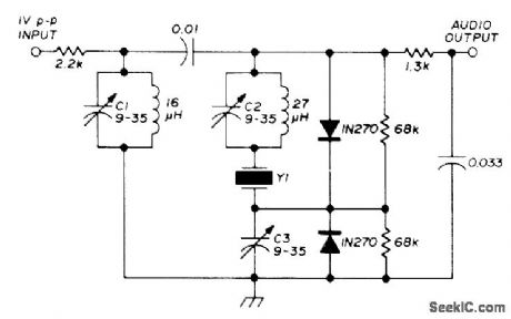
Inexpen sive third-overtone CB crystal used at 9-MHz fundamental serves as high-performance discriminator for VHF FM receiver. Adjust C3 for zero voltage with unmodulated carrier at or near center frequency. Adjust CI and C2 with AF sine wave applied to FM signal generator, using CR0 to check distortion of recovered sinewave. With 1 V P-P IF signal at 9 MHz and 5-kHz deviation, recovered audio will be about 1 V P-P at lower audio frequencies. Good limiter is required ahead of discriminator for AM rejection.-G. K.Shubert, Crystal Discriminator for VHF FM, Ham Radio, Oct. 1975, p 67-69. (View)
View full Circuit Diagram | Comments | Reading(2634)
SELF_TUNED_ULTRASONIC_GENERATOR
Published:2009/7/23 22:21:00 Author:Jessie
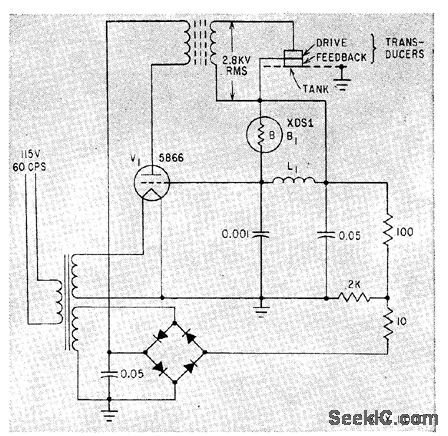
Current from feedback transducer goes through ballast lamp B1, keeping oscillator circuit V1 tuned to desired frequency between 20 and 40 kc.-S. Vogel, Ultrasonic Equipment in Industry, Electronics, 34:4, p 52-55. (View)
View full Circuit Diagram | Comments | Reading(783)
MULTI_WAVEFORM_GENERATOR
Published:2009/7/23 22:35:00 Author:Jessie
Uses double-bootstrap sweeps to generate triangular wave. Can be free-running or driven by external generator. Polarity-sensitive trigger circuit controls sweeps.-J. E. Curry, Multi-Waveform Generator, Electronics, 32:46, p 83. (View)
View full Circuit Diagram | Comments | Reading(828)
LINEAR_BOOTSTRAP
Published:2009/7/23 22:27:00 Author:Jessie
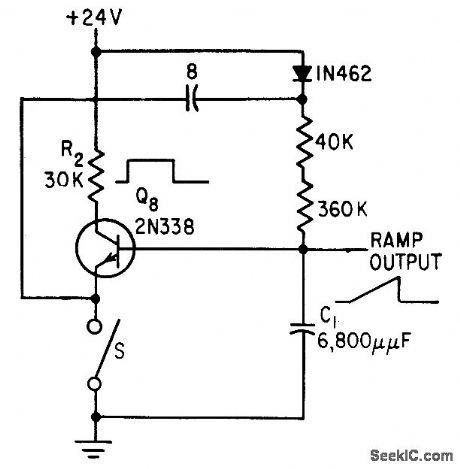
Charging current of C1 is kept constant, resulting in high linearity of ramp output. Positive-going square wave is on collector of Q8 while ramp is being generated.-D. A Williams Jr., Transistors Ruggedize Airborne Telemetry Keyer, Electronics, 31:37, p 81-83. (View)
View full Circuit Diagram | Comments | Reading(912)
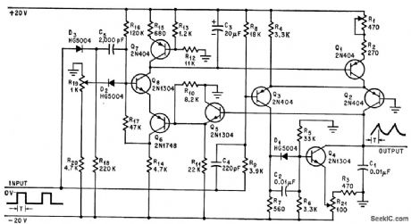
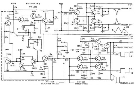
20_100000_CPS_TRIANGULAR_WAVE_GENERATOR
Published:2009/7/23 22:26:00 Author:Jessie
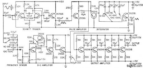
Sinusoidal frequency changes are con verted into proportional d-c volthage and fed into pulse amplifier and integrator to generate constant-amplitude triangular waveform for measuring dynamic linearity of amplifier as function of frequency. Schmitt trigger con verts input sine wave to constant-amplitude square wave. Frequency sensor produces d-c voltage proportional to frequency to serve as d-c source for pulse amplifier and integrator.-D. E. Cottrell, Frequency Sensor Stabilizes Triangular-Wave Generator, Electronics, 37:9, p 38-40. (View)
View full Circuit Diagram | Comments | Reading(840)
TUNNEL_DIODE_TRANSCEIVER
Published:2009/7/23 22:49:00 Author:Jessie
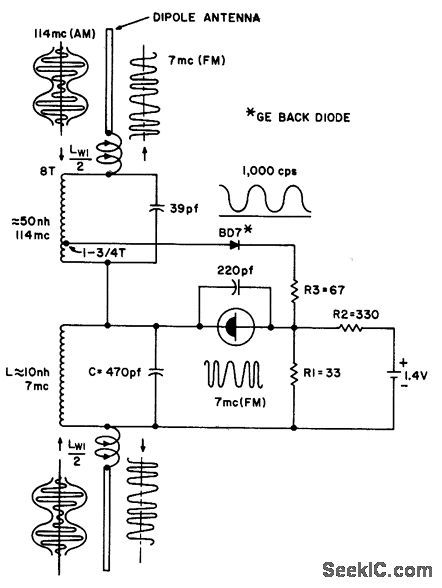
Is tuned for 114.Mc am signal and 7.Mc f-m output signal. 1N3714 tunnel diode acts as 7-Mc r-f oscillator and frequency modulator, while BD-7 back diode is 114-Mc detector.- Transister Manual, Seventh Edition, General Electric Co., 1964, p 361. (View)
View full Circuit Diagram | Comments | Reading(721)
| Pages:114/195 At 20101102103104105106107108109110111112113114115116117118119120Under 20 |
Circuit Categories
power supply circuit
Amplifier Circuit
Basic Circuit
LED and Light Circuit
Sensor Circuit
Signal Processing
Electrical Equipment Circuit
Control Circuit
Remote Control Circuit
A/D-D/A Converter Circuit
Audio Circuit
Measuring and Test Circuit
Communication Circuit
Computer-Related Circuit
555 Circuit
Automotive Circuit
Repairing Circuit