
Signal Processing
Index 118
95_MHz_TUNABLE_CRYSTAL
Published:2009/7/2 9:27:00 Author:May
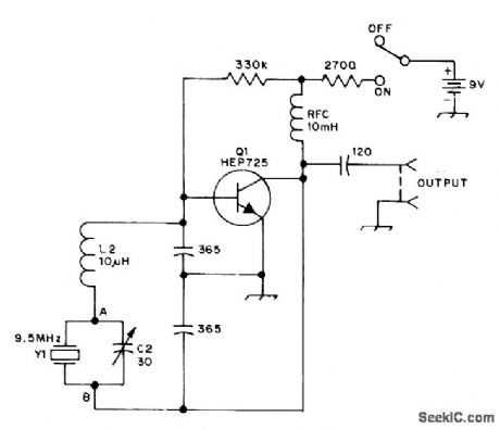
Clapp oscillator with inductance in series with crystal can be tuned with C2 as much as 100 kHz below rated frequency of crystal. Based on making crystal act as capacitive reactance below its series-resonant frequency. Circuit can be adapted to other amateur bands by keeping reactances of various components approximately the same.-L. Lisle, The Tunable Crystal Oscillator, QST, Oct. 1973, p 30-32. (View)
View full Circuit Diagram | Comments | Reading(1243)
10_MHz_VFO
Published:2009/7/2 9:25:00 Author:May
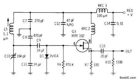
Values shown for high-stability variable-frequency oscillator give operation in 10-MHz range. Stable supply voltage is essential. Use silver mica capacitors in gate circuit for maximum stability.-E.M. Noll, FET Principles Experiments, and Projects, Howard W. Sams, Indianapolis, IN, 2nd Ed., 1975, p 193-194. (View)
View full Circuit Diagram | Comments | Reading(1568)
465_kHz_FOR_IF_TUNE_UP
Published:2009/7/2 9:24:00 Author:May
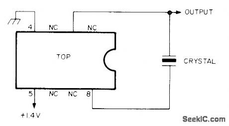
Simple crystal oscillator using National LM3909N is adjusted to exactly desired frequency with capacitor in series with pin 8. Drain from AA cell is less than 0.5 mA at 1.2 V. Use 465-kHz crystal and couple oscillator to receiver input with 100-pF capacitor. With 100-kHz crystal, circuit will generate strong harmonics beyond 30 MHz; to zero-beat with WWV, use about 10 pF in series with erystal.-I. Queen, Simple Crystal Oscillator, Ham Radio, Nov, 1977, p 98. (View)
View full Circuit Diagram | Comments | Reading(1433)
5_55_MHz_VFO
Published:2009/7/2 9:23:00 Author:May
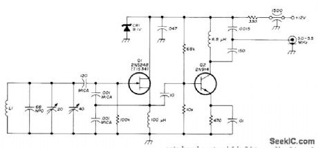
Used in solid-state five-band communication receiver. Temperature compensation is provided by 20-pF trimmer that sets band center L1 is 34 turns No.24 on Amidon T50-6 toroid core.-P. Moroni, Solid-State Communications Receiver Ham Radio, Oct,1975, P 32-41 (View)
View full Circuit Diagram | Comments | Reading(2140)
20_100_MHz_OVERTONE_CRYSTAL
Published:2009/7/2 9:23:00 Author:May
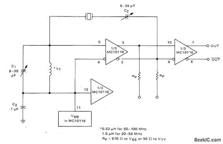
Adiustable tank circuit C1L1 ensures operation at desired crystal overtone. Reference voltage for differential amplifier is supplied internally by Motorola 10116 IC and is nominally-1.3 V.-B. Blood, IC Crystal Controlled Oscillators, Motorola, Phoenix, AZ, 1977, AN-417B, P 3. (View)
View full Circuit Diagram | Comments | Reading(1109)
TTL_459_MHz_CRYSTAL
Published:2009/7/2 9:22:00 Author:May
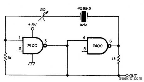
Uses FT243 crystat hand-ground to 4.5895 MHz, with 50-pF series capacitor allowing frequency to be trimmed to exactly 4.59 MHz for use in AFSK generator.-J. Nugues, AFSK Generator, Ham Radio, July 1976, p 69. (View)
View full Circuit Diagram | Comments | Reading(906)
4_MHz_CRYSTAL
Published:2009/7/2 9:21:00 Author:May
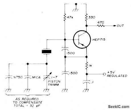
High-stability crystal oscillator usestwo 1500-pF capacitors to swamp out internal lmpedance changes that might cause frequency drift. For best stability when used as frequency standard, choose high-accuracy 4-MHz crystal.-B. Kelley, Universal Frequency Standard, Ham Radilo, Feb. 1974, p 40-47. (View)
View full Circuit Diagram | Comments | Reading(2469)
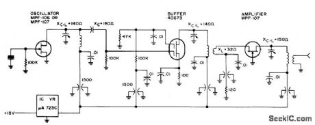
200_MHz_WITH_OSCI_LLATOR_DOUBLER
Published:2009/7/2 9:21:00 Author:May
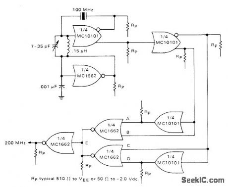
One section of Motorola MCI0101 is connected as 100-MHz crystal oscillator having crystal in series with feedback loop. LC tank circuit tunes 100-MHz harmonic of crystal and can be used to adjust circuit to exact frequency. Second section of IC serves as buffer and gives complementary 100-MHz signals for frequency doubler having two MC10101 gates as phase shifters and two MC1662 NOR gates. Outputs of MC1662s are wired-OR connected to give 200-MHz signal. One of remaining MC1662 gates is used as bias generator for oscillator.-B. Blood, IC Crystal Controlled Oscillators, Motorola, Phoenix, AZ, 1977, AN-417B, p 5. (View)
View full Circuit Diagram | Comments | Reading(983)
STABLE_CRYSTAL
Published:2009/7/2 9:19:00 Author:May
Stability is good enough for microwave transmitter frequency control. Will operate with fundamental or overtone crystals from 1.6 to 160 MHz, whh coils and capacitors being chosen for frequency in use.-Circuits, 73 Magazine, May 1973, p 105. (View)
View full Circuit Diagram | Comments | Reading(1427)
Transceivers_with_external_capacitors_5_V
Published:2009/7/24 1:58:00 Author:Jessie

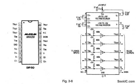
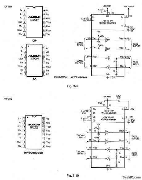
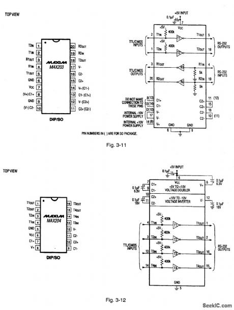
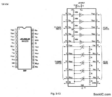
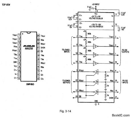
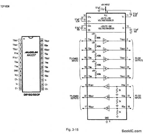
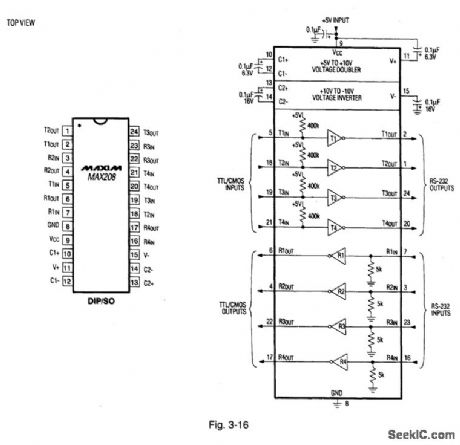
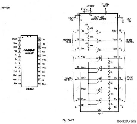
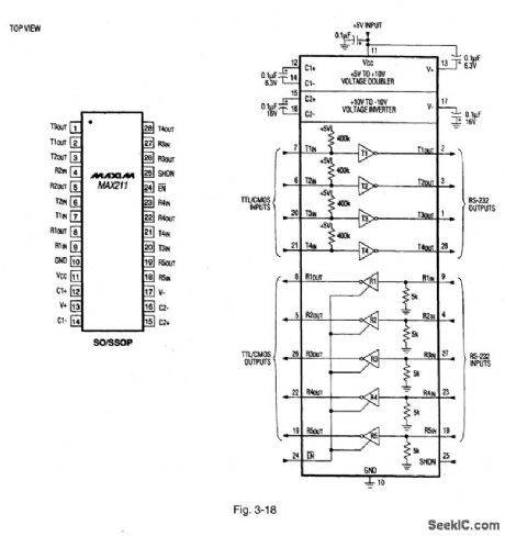
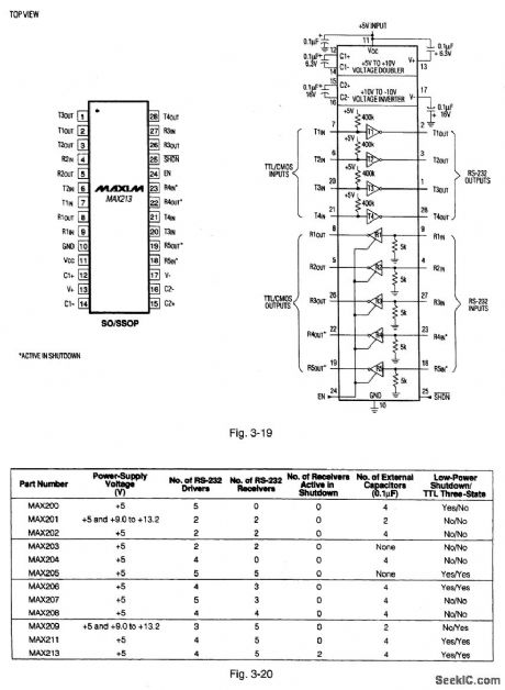
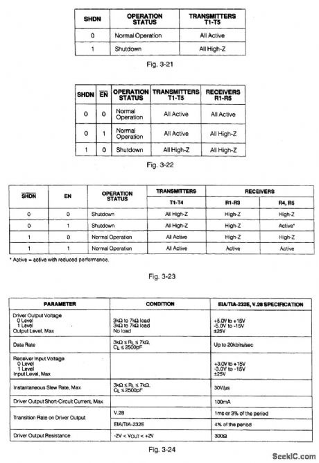
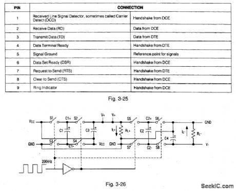
Figures 3-8 through 3-19 show typical application circuits and pin configurations for the MAX200-MAX211/MAX213. Figure 3-20 shows the selection table for these ICs. Figures 3-21, 3-22, and 3-23 show the control-pin configurations for the MAX200, MAX205/06/11, and MAX213, respectively. Figure 3-24 shows a summary of EIA/TIA-232E, V.28 specifications. Figure 3-25 shows DB9 cable connections commonly used for EIA/TIA-232E and V.24 asynchronous interfaces.These ICs are designed for RS-232 and V.28 communication interfaces, where t12 V supplies are not available. On-board charge pumps (Fig. 3-26) convert the +5-V input to the 110 V needed for RS-232 output levels. The MAX201 and MAX209 operate from +5 V and +12 V, and contain a +12-V to -12-V charge-pump voltage converter. The drivers and receivers of these ICs meet all EIA/TIA-232E and CCITV V.28 specifications at data rates of 20 kbits/second. The drivers (except MAX202, MAX203) maintain the ±5-V EIA/TIA-232E output signal levels at data rates in excess of 120 kbits/second, when loaded in accordance with the specification. The MAX200/205/206/211 have a 5-μW shutdown mode to conserve energy. The MAX213 has an active-low shutdown and an active-high receiver-enable control, Two receivers In the MAX213 are active、allowing ring indicator (Ri) to be monitored easily using only 75μW of power. MAXIM NEWRELEASES DATA Book, 1995, P.2-23, 2-28, 2-29, 2-30, 2-31, 2-32, 2-33, 2-34, 2-35, 2-36, 2-37, 2-38, 2-39, 2-40. (View)
View full Circuit Diagram | Comments | Reading(728)
TIMER_AS_OSCILLATOR
Published:2009/7/2 9:18:00 Author:May
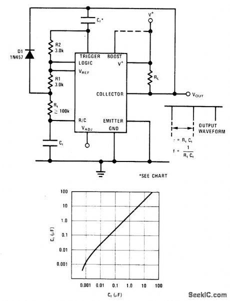
Output of National LM122 timerisfed back to trigger input through capacitor to give self-starting oscillator. Frequency is 1/RtCt. Output is narrow negative pulse havipg duration of about 2R2Cf. Conservative value for Cf for optimum frequency stability can be chosen from graph based on size of timing capacitor Ct.-C. Nelson, Versatile Timer Operates from Microseconds to Hours, National Semiconductor, Santa Clara, CA, 1973, AN-97, p 10. (View)
View full Circuit Diagram | Comments | Reading(769)
7_MHz_±_50_kHz
Published:2009/7/2 9:17:00 Author:May
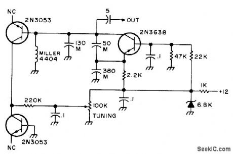
Requires no tuning capacitors. Collector-to-base iunctions of two 2N3053 transistors perform function of varactor diodes to provide tuning over range of about 50 kHz centered on 7 MHz. Capacitors marked M should be mica.-An Accessory VFO-the Easy Way, 73 Magazine, Aug. 1975, p 103 and 106-108. (View)
View full Circuit Diagram | Comments | Reading(1276)
OSCILLATOR_OUTPUT_STAGE
Published:2009/7/24 2:04:00 Author:Jessie
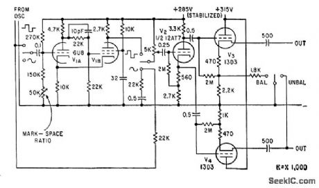
Used with incremental-tuning precision R-C oscillator for testing and aligning equipment having sharp resonances. oscillator signal is fed through phase splitter V2 to cathode followers V3 and V4 in push-pull, to provide symmetrical output when required. Will feed either 600-ohm unbalanced load or two 300-ohm outputs balanced with respect to ground, with 10 mw maximum output.-J. H. Reyner, Precision Oscillator with Incremental Tuning, Electronics, 33:16, p 76-78. (View)
View full Circuit Diagram | Comments | Reading(764)
PRECISION_VFO
Published:2009/7/2 9:15:00 Author:May
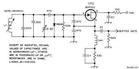
Permeability-tuned oscillator provides stability and linearity at low cost for receivers with 160-meter tunable IF stages. L1 has 28 turns No. 36 enamel closewound on J. W. Miller form 64A022.2. Article covers construction of tuning dial, incuding contouring of L1 core to give good dial linearity. Frequency coverage is 2.255-2.509 MHz. Direct-reading dial is accurate within 1.5 kHz over entire 250-kHz tuning range.-W. A. Gregoire, Jr., A Permeability-Tuned Variable-Frequency Oscillator, QST, March 1978, p 26-28. (View)
View full Circuit Diagram | Comments | Reading(2379)
20_500_kHz_CRYSTAL
Published:2009/7/2 9:15:00 Author:May
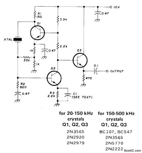
Series-mode oscillator requires no tuned circuit, gives choice of sine or square output, and has good frequency and mode stability. Works nicely with troublesome FT241 crystals. If any crystal fails to start reliably, increase R1 to 270 ohms and R2 to 3.3K. For squire-wave operation, C1 is 1-μF nonelectrolytic. Omit C1 for sine-wave operation; harmonic output is then quite low, whh second harmonic typically -30 dB. Output is about 1.5-VRMS sine wave or 4-V square wave.-R. Harrison, Survey of Crystal Oscillators, Ham Radio, March 1976, p 10-22. (View)
View full Circuit Diagram | Comments | Reading(1604)
50_500_kHz_CRYSTAL
Published:2009/7/2 9:13:00 Author:May
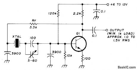
Parallel-mode low-frequency oscillator makes excellent BFO for 455 kHz. If oscillator will not start, reduce value of feedback resistor RF. Increasing RF reduces harmonic output, but oscillator may then take up to 20 s to reach full output. For crystals with specified load capacitance of 30 or 50 pF, remove 100-pF capacitor C1 in series with crystal. Q1 is 2N2920, 2N2979, 2N3565, 2N3646, 2N5770, BC107, or BC547.-R. Harrison, Survey of Crystal Oscillators, Ham Radio, March 1976, p 10-22. (View)
View full Circuit Diagram | Comments | Reading(5057)
ESD_protected_transceivers_5_V
Published:2009/7/24 2:01:00 Author:Jessie
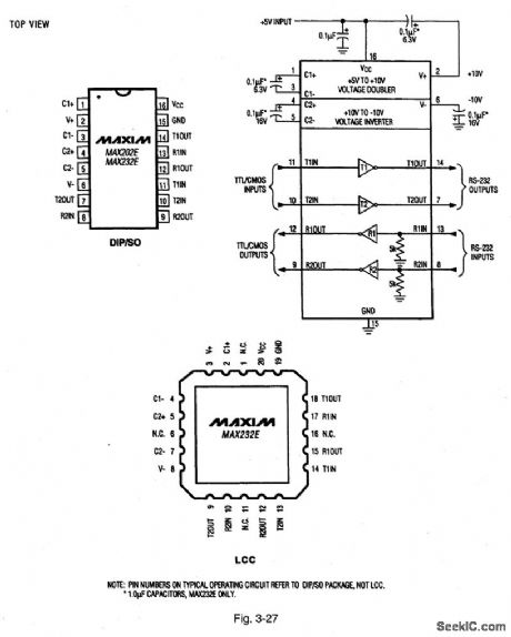
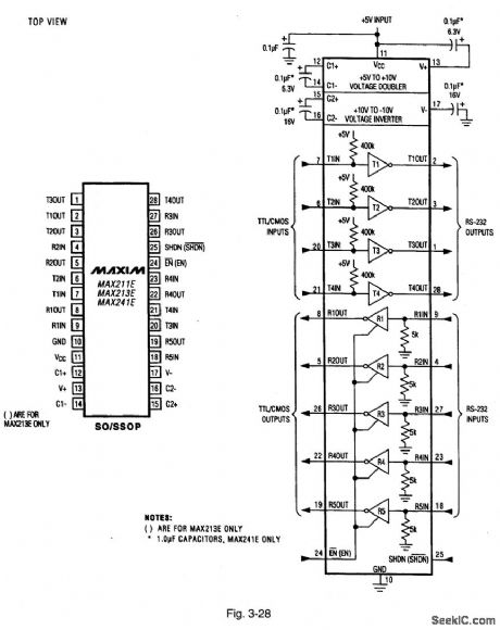
Figure 3-27 shows the typical application circuits and pin configurations for the MAX202E,232E. Figure 3-28 shows the MAX211E, 213E, 241E. These ICs are designed to operate in harsh environments, but still meet EIA/TIA-232E specifications. Each transmitter output and receiver input is protected against ±15-kV electrostatic discharge (ESD). MAXIM NEW RELEASES DATA Book 1995, P.2-54, 2-55. (View)
View full Circuit Diagram | Comments | Reading(716)
48_MHz
Published:2009/7/2 9:12:00 Author:May
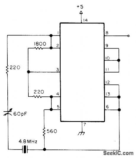
Uses all four sections of 7400 quad dual-input NAND gate to give 4.8 MHz output at pin 8, as harmonic-rich square wave. Can cause severe television interference during testing. Article gives five other crystal oscillator circults using same IC.-A. MacLean, How Do You Use ICs?, 73 Magazine, Oct. 1976, p 38-41. (View)
View full Circuit Diagram | Comments | Reading(1269)
7_MHz
Published:2009/7/2 9:12:00 Author:May
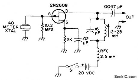
Uses single Siliconix 2N2608 FET. Keep leads short. Coil can be air-wound or permeability-tuned. If tuning capacitor is variable, coil value can be fixed. RF output level depends on circuit voltages and on activity of crystal used.-Q & A, 73 Magazine, April 1977, p 165. (View)
View full Circuit Diagram | Comments | Reading(1036)
MODULATED_CRYSTAL
Published:2009/7/2 9:11:00 Author:May
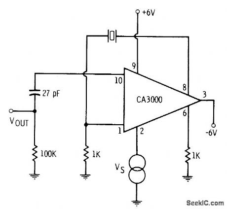
CA3000 differential amplifier is operated as efficient crystal-controlled oscillator. Output frequency depends on crystal. If desired, RF output can be modulated with low-frequency tone applied between pin 2 and ground.-E. M. Noll, Linear IC Principles, Experiments, and Proiects, Howard W. Sams, Indianapolis, IN, 1974, p 91. (View)
View full Circuit Diagram | Comments | Reading(1056)
| Pages:118/195 At 20101102103104105106107108109110111112113114115116117118119120Under 20 |
Circuit Categories
power supply circuit
Amplifier Circuit
Basic Circuit
LED and Light Circuit
Sensor Circuit
Signal Processing
Electrical Equipment Circuit
Control Circuit
Remote Control Circuit
A/D-D/A Converter Circuit
Audio Circuit
Measuring and Test Circuit
Communication Circuit
Computer-Related Circuit
555 Circuit
Automotive Circuit
Repairing Circuit