
Signal Processing
Index 120
8O0_kHz_OSCILLATOR
Published:2009/7/2 7:28:00 Author:May
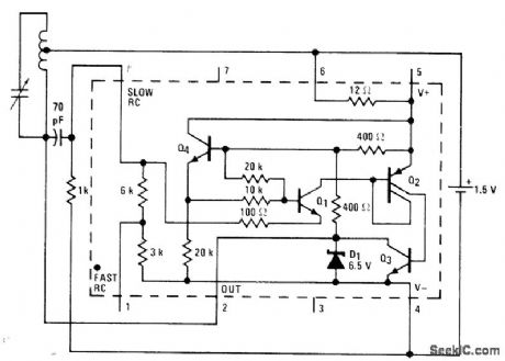
National LM3909 IC operating from single 1.5-V cell is used with standard AM radio ferrite antenna coil having tap 4070 of turns from one end, with standard 365 pF tuning capacitor across coil. Developed for demonstrating versatility of this low-voltage IC.- Linear Applications, Vo1. 2. National Semiconductor, Santa Clara, CA, 1976, AN-154, p8. (View)
View full Circuit Diagram | Comments | Reading(777)
SWITCHED_CRYSTALS
Published:2009/7/2 7:28:00 Author:May
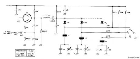
High stability is combined with multichannel selection by diode switching of crystals in range of 2-20 MHz, used in series-resonant mode. L1 is about 30 μH at 2 MHz and 1 μH at 20 MHz. Q1 is 2N708, HEP50, BC108, or similar NPN RF type Diodes are switching types such as BAY67.-U. Rohde, Stable Crystal Oscillators, Ham Radio, June 1975, p 34-37. (View)
View full Circuit Diagram | Comments | Reading(1321)
JFET_PIERCE_CRYSTAL
Published:2009/7/2 7:27:00 Author:May
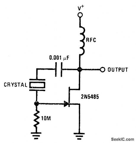
Basic JFET oscillatorcircuit permits use of wide frequency range of crystals. High Q is maintained because JFET gate does not load crystal, thereby ensuring good frequency stability.- FET Databook, National Semiconductor, Santa Clara, CA, 1977, p 6-26-6-36. (View)
View full Circuit Diagram | Comments | Reading(1022)
12_MC_CRYSTAL_STANDING_WAVE_DETECTOR
Published:2009/7/24 2:17:00 Author:Jessie
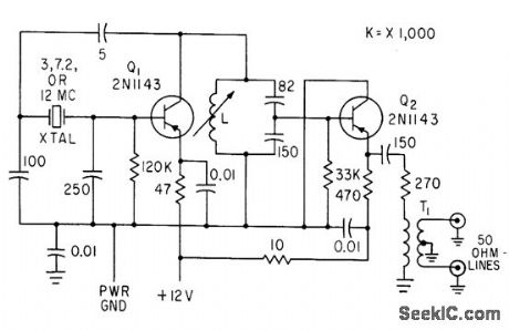
Transistorized crystal oscillator Q1 and emitter-follower Q2 feed 1 V rms into two balanced transmission lines going to standing-wave detector.-O. C. Haycock, and K. D. Baker, Measuring Antenna Impedance in the lonosphere, Electronics, 34:2, p 88-92. (View)
View full Circuit Diagram | Comments | Reading(619)
EMERGENCY_NOISE_GENERATOR
Published:2009/7/2 7:22:00 Author:May
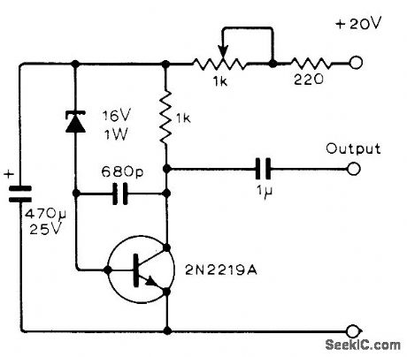
Simple circuit generates noise in audio range at wideband level adjustable with 1 K pot from 0 to over 1 V. lf 680-pF capacitor is omitted, noise output goes up to 30 MHz with wideband level more than 5 V.-D. Di Mario. Simple Noise Generator. Wireless World. May 1978. p 70. (View)
View full Circuit Diagram | Comments | Reading(1823)
PRECISION_R_C_OSCILLATOR
Published:2009/7/24 2:17:00 Author:Jessie
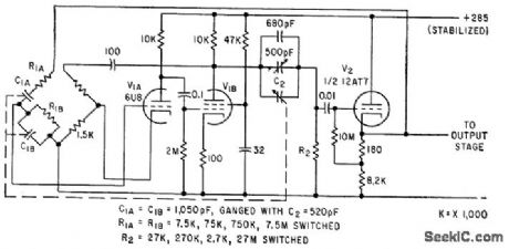
Used in signal generator for testing systems by varying frequency over very small limits, as in aligning filters having sharp resonance curves. Cathode follower V2 is included in feedback loop to reduce loading on bridge network. Covers 25 cps to 250 kc in four ranges, with incremental control giving increment of 2% of maximum frequency in each range.-J. H. Reyner, Precision Oscillator with Incremental Tuning, Electronics, 33:16, p 76-78. (View)
View full Circuit Diagram | Comments | Reading(1068)
3955_4455_MHz_VFO
Published:2009/7/2 7:12:00 Author:May
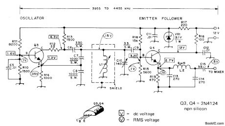
Basic Colpitts LC oscillator designed for 80-meter receivel wiith 455-kHz IF uses zener in supply line to minimize frequncy drift. Emitter-follower buffer contributes to stability by isolating oscillator frommlxer Low-pass filter C13-L2-C14 attenuates harmonic currents developed in Q3 and Q4. L1 is Miller 4503 1.7-2.7 μH variable inductor. L2 is 48 turns No.30 enamel closewound on 1/4-inch wood dowel or polystyrene rod. Main tuning capacitor C10 can be 365-pF unit with six of rear rotor plates removed.-D. DeMaw and L. McCoy, Learning to Work with Semiconductors, QST, June 1974, p 18-22 and 72. (View)
View full Circuit Diagram | Comments | Reading(2290)
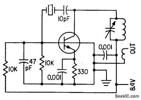
1O_2O_MHz_CRYSTAL
Published:2009/7/2 7:11:00 Author:May
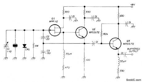
Modification of basic Colpitts crystal oscillator has excellent load capacitance correlationand temperature stability. Crystal will oscillate very close to its series resonant point. Component values are optimized for 10-20 MHz. Emitter-follower Q2 provides power gain for feedback energy and gives high crystal activity without changing phase angle of signal. Output buffer Q3 prevents loading of oscillator. Q1 is low-cost Motorola JFET, but practically any other JFET will work CR1 is 1N914 or 1N4148.-D. L. Stoner, High-Stability Crystal Oscillator, Ham Radio, Oct. 1974, p 36-39. (View)
View full Circuit Diagram | Comments | Reading(1686)
1_20_MHz_FUNDAMENTAL_CRYSTAL
Published:2009/7/2 7:02:00 Author:May
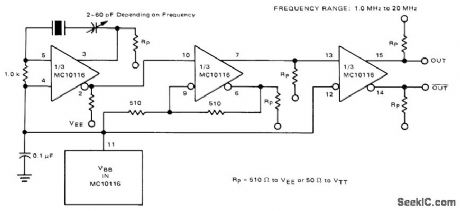
Oscillator requires no resonant tank circuit for frequencies below 20 MHz. Use of noninverting output makes oscillator section of Motorola MC10116 IC function simply as amplifier. Second section is connected as Schmitt trigger to improve signal waveform. Third section is buffer providing complementary outputs.-B. Blood, IC Crystal Controlled Oscillators, Motorola, Phoenix, AZ, 1977, AN-417B, p 4. (View)
View full Circuit Diagram | Comments | Reading(895)
TIMING_SIGNAL_GENERATOR
Published:2009/7/24 2:16:00 Author:Jessie
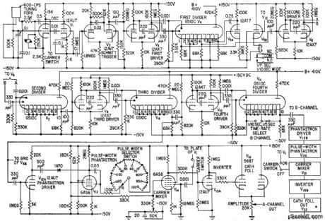
Delivers pulses of controlled duration, amplitude, and carrier content at 1 pps in channel A and either 1 per 5 sec or 1 per 10 sec in channel B. Any decimal frequency multiple of 1, 2, or 5 from 100 to 0.1 cps may be obtained. Timed pulse signals can be controlled both in amplitude and width, and turned on or off at will.-D. E. Minow, Timed-Singal Generator With Flexible Output, Electronics, 32:10, p 52-53. (View)
View full Circuit Diagram | Comments | Reading(743)
Dual_transceiver_18_V_to_425_V
Published:2009/7/24 2:15:00 Author:Jessie
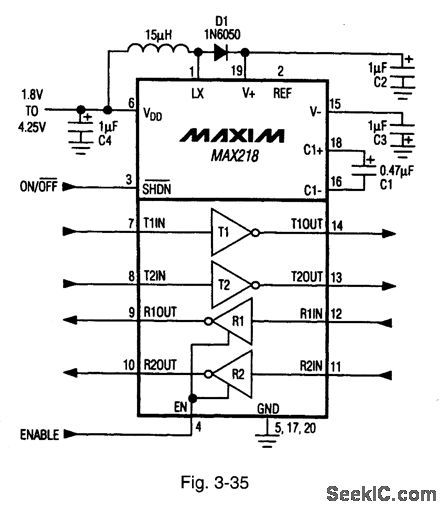
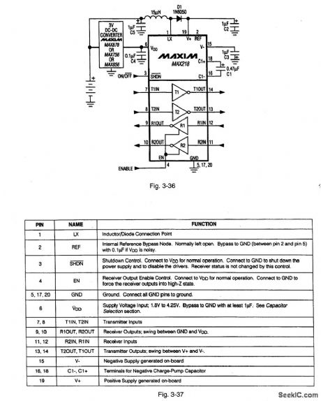

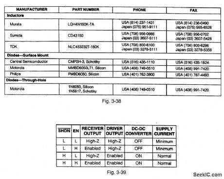
Figure 3-35 shows a typical application circuit for single-supply operation of the MAX218. Figure 3-36 shows the connections for operation from unregulated and regulated supplies. Figure 3-37 shows the pin descriptions. Figure 3-38 shows suggested component suppliers. This IC runs on two alkaline (NiCd or NiMH) cells to provide full EIA/TIA-232E and V.28/V.24 communications interface. True RS-232 and EIA/TIA-562 voltage levels are maintained with a wide +1.8-V to +4.25-V operating range. A shutdown mode reduces current to 1μA. The receivers can be enabled or disabled under logic control. Figure 3-39 shows the shutdown and enable/disable mode logic. The data rate is guaranteed at 120 kbps. MAXIM NEW RELEASES DATA BOOK, 1995, P. 2-79, 2-80, 2-81, 2-82. (View)
View full Circuit Diagram | Comments | Reading(744)
METAL_FOIL_SPOTWELDING_CONTROL
Published:2009/7/24 2:15:00 Author:Jessie
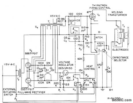
Permits precise control of high-energy capacitor discharge used in welding extremely thin and highly conductive foils or fine wires. Heat control provides range of 650 to 1,500 v for level at which energy is stored, and selector switch gives choice of 50, 100, and 200 mfd for storage capacitor.-J. Markus, Handbook of Electronic Control Circuits, McGraw-Hill, New York, 1959, p 321. (View)
View full Circuit Diagram | Comments | Reading(1383)
ATTACK_CONTROL_AMPLIFIER
Published:2009/7/24 2:22:00 Author:Jessie
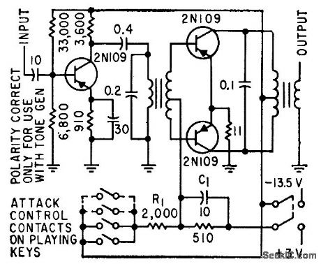
Used with tone timbre generator to provide gradual attack for electronic music demonstration.-W. S. Pike and C. N. Hoyler, Synthesizing Timbre for Electronic Musical Tones, Electronics, 32:22, p 92-94. (View)
View full Circuit Diagram | Comments | Reading(680)
CARRIER_SYNTHESIZER
Published:2009/7/24 2:21:00 Author:Jessie
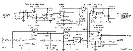
Generates signal midway in frequency between two input frequency tones, for mixing with output of linear amplifier under test.-G. H. Smith, Distortion Monitor Checks Linear Amplifier Characteristics, Electronics, 34:27, p 57-59. (View)
View full Circuit Diagram | Comments | Reading(728)
20_CPS_TO_40_KC_WITH_WIEN_BRIDGE
Published:2009/7/24 2:20:00 Author:Jessie
Range is covered in four steps. Two-stage oscillator is followed by buffer that delivers 3.5 v to 2,000-ohm load.-V. Glover, Using a New Device: Field-Effect Transistor Oscillators, Electronics, 35:51, p 44-46. (View)
View full Circuit Diagram | Comments | Reading(715)
CONSTANT_AMPLITUDE_SINE_WAVE_SOURCE
Published:2009/7/24 2:20:00 Author:Jessie
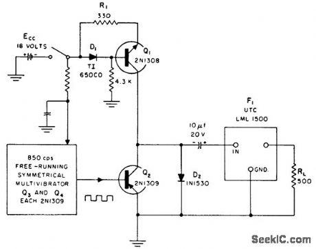
Battery-operated fixed-frequency calibration source gives constant amplitude within 1% between 0 and 70℃, with less than 1% harmonic distortion. Circuit generates square wove, then converts if to sine wave in low-pass filter network. Frequency remains constunt at around 850 cps within 4% over operating temperature range.-Constant-Amplitude Sine-Wave Source, Electronic Circuit Design Handbook, Mactier Pub. Corp., N.Y, 1965, p 166. (View)
View full Circuit Diagram | Comments | Reading(771)
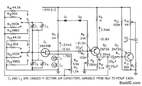
PULSE_RECEIVER_TESTER
Published:2009/7/24 2:26:00 Author:Jessie
Simulates fold conditions encountered by pulse receivers use in ionospheric soundings, by supplying powerful pulse followed by weak pulse, with variable time separation. Weak pulse can be moved through fixed strong pulse without addition of pulse amplitudes. Uses cathode-follower mixer pulser and c-w oscillator pulsing a buffer.-K. Perry, Transmitter Simulator Tests Pulse and Phase-Palh Receivers, Electronics, 33:41, p 67. (View)
View full Circuit Diagram | Comments | Reading(727)
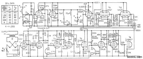
RANDOM_SIGNAL_GENERATOR
Published:2009/7/24 2:24:00 Author:Jessie

Signals arise from fluctuations in dense layer of positive ions near cathode of 2D21 grid-controlled gas-discharge tube. Used with computers to simulate random action, such as effect of wind gusts on controls of airplane.-N. D, Diamantides and C. E. McCray, Generating Random Forcing Functions for Control System Simulation, Electronics, 34:33, p 60-63. (View)
View full Circuit Diagram | Comments | Reading(1206)
20_40_CPS_VARIABLE_SWEEP
Published:2009/7/24 2:23:00 Author:Jessie
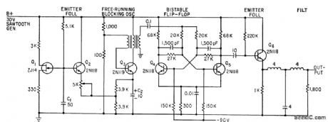
Used to lest servos and related equipment. Sawtooth waveform developed by unijunction transistor circuit is used to key blocking oscillator.-M. Rosen, Subaudio Swapt Signal Generator, Electronics, 33:17, p 67-68. (View)
View full Circuit Diagram | Comments | Reading(716)
PIERCE_TETRODE_TRANSISTOR
Published:2009/7/24 2:23:00 Author:Jessie
Tuned to third overtone of crystal fundamental. Fifth harmonic of oscillator is used as calibration frequency for c-w receiver of radio direction linden-A. T. Lloyd, Direction Finder Helps Recover Discoverer Capsule, Electronics, 34:9, p 42-45. (View)
View full Circuit Diagram | Comments | Reading(779)
| Pages:120/195 At 20101102103104105106107108109110111112113114115116117118119120Under 20 |
Circuit Categories
power supply circuit
Amplifier Circuit
Basic Circuit
LED and Light Circuit
Sensor Circuit
Signal Processing
Electrical Equipment Circuit
Control Circuit
Remote Control Circuit
A/D-D/A Converter Circuit
Audio Circuit
Measuring and Test Circuit
Communication Circuit
Computer-Related Circuit
555 Circuit
Automotive Circuit
Repairing Circuit