
Signal Processing
Index 104
REGENERATIVE_SWITCHING_TRIGGER
Published:2009/7/21 9:11:00 Author:Jessie
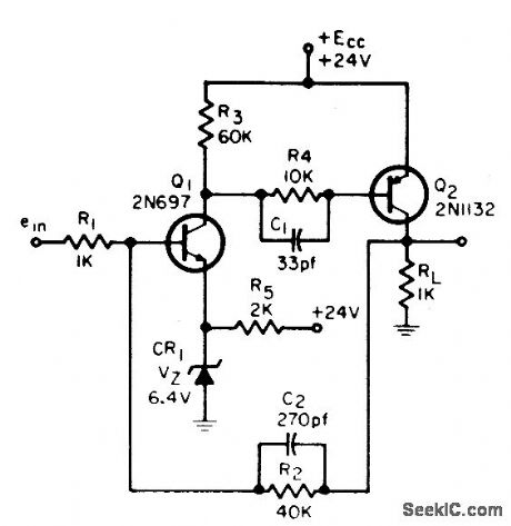
Advantages over conventional Schmitt include reduced power consumption (neither transistor conducts during off state), full range output voltage swing, and low output Impedance. Some input signal appears in output. Rise and fall times are 0.15 microsec.-R. K. Vieth, Trigger Circuit Gives Less P-diss, More V-out, EEE, 11:12,p 28. (View)
View full Circuit Diagram | Comments | Reading(1038)
VOLTAGE_MONITOR
Published:2009/7/21 9:09:00 Author:Jessie
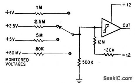
Input voltage sensitivity better than 0.7 mv is obtained from operational trigger.-P. Lelferts, Operational Trigger For Precise Control, Electronics, 37:28, p 50-55. (View)
View full Circuit Diagram | Comments | Reading(1)
DELAYED_TRIGGER_GENERATOR
Published:2009/7/21 9:08:00 Author:Jessie
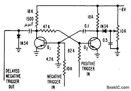
Provides controllable positive or negative delayed trigger. When used to see leading edge of multivibrator pulse on cro, trigger starts cro sweep and delay generator. After preset time, delay generator produces pulse used to trigger mvbn-H. L. Armstrong, Transistorized Trigger and Delay Generators, Electronics, 31:3, p 96-98. (View)
View full Circuit Diagram | Comments | Reading(946)
JFET_VFO
Published:2009/7/22 3:47:00 Author:Jessie
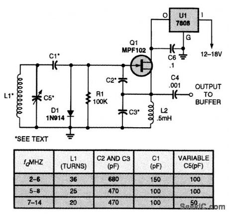
This circuit is a simple JFET-based, variable-frequency oscillator that can be used in receiver or transmitter circuits. The circuit is very stable; hence, if good-quality components and appropriate construction techniques are used, there will be very little drift in frequency. The component values listed in the table will give you a starting point to set up the oscillator to cover a desired frequency range. Inductor L1 is wound on a T50-6 toroidal core using #26 or #28 enamel-coated copper wire. The oscillator's frequency can be increased a small amount by removing a turn from the coil's winding; by the same token, the frequency can be decreased by adding a turn or two. After you have achieved the desired frequency range, cover the coil with a clear plastic coating or coil dope to keep the coil wires from moving around and causing the oscillator's frequency to shift. (View)
View full Circuit Diagram | Comments | Reading(4099)
VOLTAGE_TUNED_CLAPP_OSCILLATOR
Published:2009/7/22 3:44:00 Author:Jessie

This voltage-tuned Clapp oscillator uses a varactor diode to set its operating frequency. D1 is an NTE614. L1 is about 7/ƒ (MHz) microhenries. With the circuit shown, the frequency range is about 6 to 15 MHz. (View)
View full Circuit Diagram | Comments | Reading(990)
STATE_GENERATOR_FOR_STEPPER
Published:2009/7/7 4:34:00 Author:May
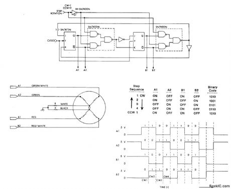
Generates high-current square-wave pulses and provides correct switching sequence for exciting stepper motor when digital display is required to show instantaneous step angle and total revolutions traveled by shaft of stepper motor. If microprocessor is used, speed and direction of motor rotation can be controlled by programming period and level of output pulses. Clock signals trigger SN7473N JK flip-flop that changes ON/OFF states of four outputs as shown in table. Clock signal is obtained from external square-wave generator or from microprocessor such as KIM-1. Article also gives digital display circuit driven by same clock.-H. Lo, Digital Display of Stepper Motor Rotation, Computer Design, April 1978,p 147-148 and150-151 (View)
View full Circuit Diagram | Comments | Reading(961)
20_METER_VFO
Published:2009/7/7 4:26:00 Author:May
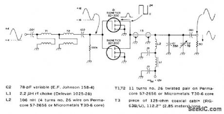
Tunes from 14.0 to 14.2 MHz、using stable Vackar design, Protective diode CR1 canbe any silicon rectifier Clamping diode CR3 improves stability by preventing conduction in gate of JFET osciliator Q1,-C,E,Galbreath、Low-Power Solid-State VFO Transmit-ter for 20 Meters,Ham Radio. Nov,1973, p 6-11 (View)
View full Circuit Diagram | Comments | Reading(1215)
SPEECH_PROCESSOR
Published:2009/7/21 21:27:00 Author:Jessie
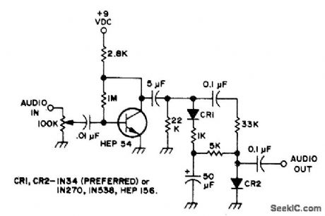
Preamplification combined with dipping or compression gives higher average level and increased intelligibility of SSB communication. Degree of compression is controlled with 100K pot that adjusts input. Output of transistor feeds passive diode compressor.Amount of compression will vary with diode type, and experimentation is suggested. Article covers construction and adjustment of circuit.-B. Barrington, Simple Audio Preamp.73Magazl'ne, Feb. 1974, p 69-70. (View)
View full Circuit Diagram | Comments | Reading(5918)
AF_RF_FROM_1_MHz
Published:2009/7/21 20:31:00 Author:Jessie
String of SN7490 decade counters divides output of 1-MHz crystal oscillator by 10 or 2 to give choice of six fixed frequencies between 1000 Hz and 100 kHz along with undivided 1 MHz. 0ne gate of SN7400 crystal oscillator drives LED to indicate that crystal is oscillating, When using external sine-wave source, input is squared by SN74121 MVBR for driving frequency divider chain. Circuit is easily modified to give other divider ratios. Applications include use as marker generator for receiver calibration up into VHF range or as signal generator for precise AF or PF square-wave signal at desired frequencies,-J,J Schultz, Poor Man's Universal Frequency Generator,73 Magazine, July 1974.p33 and 35-36. (View)
View full Circuit Diagram | Comments | Reading(2064)
1_MHz_CRYSTAL_CALIBRATOR
Published:2009/7/21 20:30:00 Author:Jessie
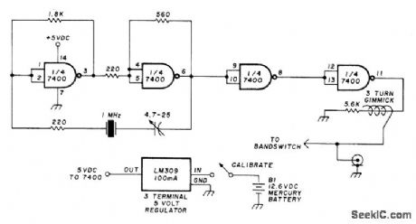
Battery-powered crystal oscillator for checking frequency calibration of communication receiver uses TTL. Regulator is in TO-5 can, which is 100-mA version of LM309.-J. J. Carr, Resurrecting the Old War Horse: New Hope for the Old Receiver, Ham Radio, Dec. 1976, p 52-55. (View)
View full Circuit Diagram | Comments | Reading(1474)
NETWORK_TESTER
Published:2009/7/21 20:22:00 Author:Jessie
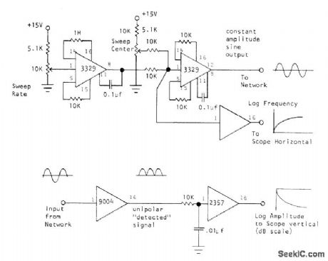
Sweep generator produces time-varying constant-amplitude frequency signal for network under test, with out-put of network converted to logarithmic DC voltage for display of amplitude or gain on decibel scale of CRO or recorder. Sawtooth voltage for sweep, generated by first Optical Electronics 3329 IC, drives another 3329 that converts sawtooth into logarithmic signal for log-frequency output. Detector uses 9004 absolute-value module as linear detector, with 2357 logamp converting output to decibel scale. Resulting display is Bode plot of frequency response.- A Simple Sweep Generator, Optical Electronics, Tucson, AZ, Application Tip 10201. (View)
View full Circuit Diagram | Comments | Reading(990)
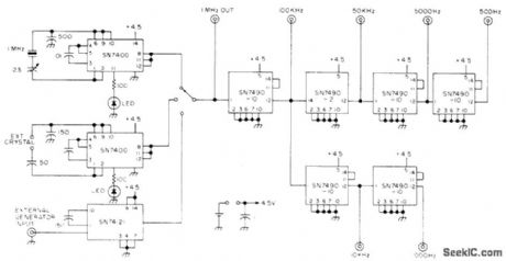
UNIVERSAL_SIGNAL_GENERATOR
Published:2009/7/21 20:20:00 Author:Jessie
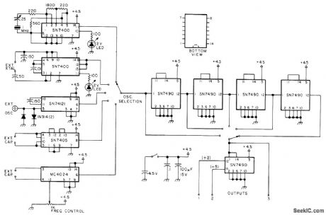
Collection of IC oscillators and dividers generates square waves from HF down to subaudible AF, along with markers up into VHF. Selectable oscillator section feeds fixed string of four divide-by-10 stages. Extra SN7490 divider can be switched in at various points along string to add divide-by-5 and divide-by-2 functions. LED in 1-MHz crystal stage indicates that circuit is oscillating. Second stage can be used with any external crystal up into low VHF range. Third stage accepts and conditions extemal sine or square input for feeding to divider chain. Extemal capacitor for fourth stage tunes square-wave generator from several hertz to several megahertz. Optional fifth stage is VCO for entire HF range up to 25 MHz.-J. Schultz, Updated Universal Frequency Generator, 73 Magazine, Nov. 1976, p 50-52. (View)
View full Circuit Diagram | Comments | Reading(1567)
1_20_Hz_SINE
Published:2009/7/21 20:40:00 Author:Jessie
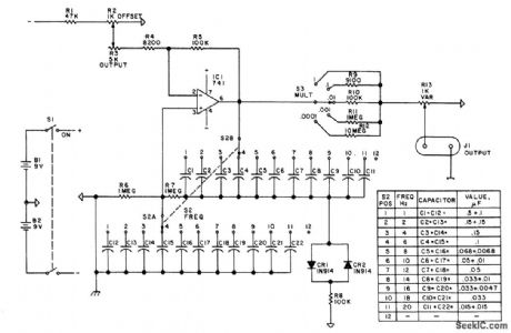
Designed to complement usual lab sine-wave generator that goes down to only 20 Hz, by providing discrete switch-selected output frequencies of 1 Hz and 2-20 Hz in 2-Hz steps. Output attenuator uses pot and switch to set output at any value within range of five decades. Circuit uses 741 opamp in Wien-bridge oscillator having four-element RC network in positive feedback path of amplifier (R6 in parallel with capacitor selected by S2A, and R7 in series with capacitor of S2B), so oscillation occurs at frequency where phase shift occurs. Article gives construction details Offset adjustment R2 may need touching up as batteries rundown.-D Hileman and L Hileman.V-V-V LF Generator,73 Magazine. Holiday issue 1976,p97-99. (View)
View full Circuit Diagram | Comments | Reading(961)
2_MHz_STANDARD_WITH_DIVIDERS
Published:2009/7/21 20:39:00 Author:Jessie
Can be used for calibration of frequency meters, frequency counters, and amateur receivers. Two crystal oscillators (2 MHz and 100 kHz) feed two 7490 decade counters through isolation amplifier. Arrangement gives frequency division by 2, 4, 10, 20, and 100 for each oscillator, with all frequencies rich in harmonics and usable through 144 MHz. Counter reset gates at pins 2, 3, 6, and 7 and ground at pin 10 must be connected to common terminal for all modes of operation, Supply should not exceed 5.5 V.-J. M. Janicke, A Wide-Range Crystal-Controlled Frequency Standard, QST, July 1976, p 27-28. (View)
View full Circuit Diagram | Comments | Reading(1362)
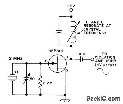
1_10_N1Hz_CRYSTAL
Published:2009/7/21 20:38:00 Author:Jessie
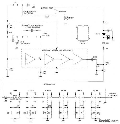
Stable crystal test oscillator takes any crystal in frequency range with no tuning adjustments. Uses single Motorola MC799P IC in circuit that provides 32-pF crystal loading. Trimmer may be used to adjust crystal for exact frequency if desired. Circuit is not critical. Bias pot compensates for battery voltage changes. Output attenuator uses standard resistor values to provide up to 126 dB of output signal control. Meter serves as battery tester and gives instant indication of crystal activity when circuit is used for testing crystals.-A A. Kelley, Crystal Test Oscillator and Signal Generator, Ham Radio, March 1913, p 46-47. (View)
View full Circuit Diagram | Comments | Reading(751)
1_Hz_TO_1_MHz
Published:2009/7/21 20:35:00 Author:Jessie
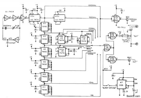
Low-cost secondary frequency standard generates marker signals of 1000, 500, 100, 50, 25, 10, 5, and 1 kHz and 100, 10, and 1 Hz, with harmonic markers usable well beyond 30 MHz. Two TTL output levels are available as clocks or signal injectors for checking TTL.Short-term accuracy is about 1 part in 106. Unit is easily aligned to WWV with shortwave receiver. Frequency-burst mode turns output on and off 10 times per second, for identification of markers in crowded band of receiver. Article covers construction and operation in detail, and gives circuit for suitable regulated power supply having standby battery.-T. Shankland, Build a Super Standard, 73Magazine, Oct. 1976, p 66-69. (View)
View full Circuit Diagram | Comments | Reading(0)
SECONDARY_STANDARD
Published:2009/7/21 20:33:00 Author:Jessie
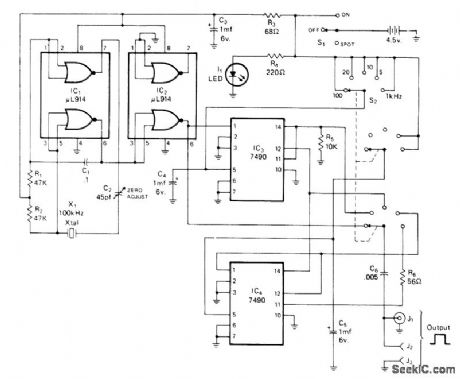
Provides switch selected square-wave outputs of 100, 20, 10, 5, and 1 kHz, calibrated with receiver tuned to WWV frequency. 100-kHz clock signal is generated by crystal oscillator IC1. Half of IC2 is buffer between oscillator and first decade counter IC3, used to generate 10- and 20-kHz outputs. Sec-ond decade counter IC4 gives 1 and 5 kHz.-E.R. Spadoni, A Versatile Secondary Frequency Standard, CQ, Sept. 1975, p 31-32. (View)
View full Circuit Diagram | Comments | Reading(814)
HF_VHF_MARKERS
Published:2009/7/21 21:05:00 Author:Jessie
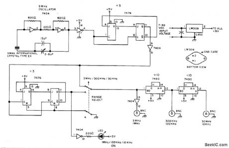
Provides markers needed for most amateur radio bands, including 30 and 300 kHz for VHF FM operation and 10 and 100 kHz for 2-m FM operation. When LED is on, outputs are 1 MHz, 100 kHz, and 10 kHz. When LED is off, outputs are 3 MHz, 300 kHz, and 30 kHz. Uses 7404 TTL hex inverter as crystal oscillator, with 2-8 pF trimmer for zeroing crystal with WWV. All 7476 TTL dual JK flip-flops are connected to divide by 3.-F. E, Hinkle, Inexpensive HF-VHF Frequency Standard, 73 Magazine, April 1976, p 62-63. (View)
View full Circuit Diagram | Comments | Reading(909)
455_kHz_FREQUENCY_MODULATED
Published:2009/7/21 21:03:00 Author:Jessie
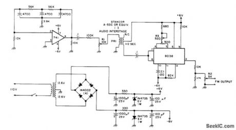
Can be used to align IF amplifier and quadrature detector of FM receivers. Unit is stable and provides ample deviation for amateur receivers. Uses 8038 function generator and 741 opamp connected as audio oscillator to provide about 1000-Hz modulating voltage. Includes deviation control R1, output level control R2, and carrier frequency control R3. Adjust 500-ohm pot between pins 4 and 5 of 8038 for clean sine-wave output on CRO. Adjust R3 to give 455 kHz as measured by meter or frequency counter. To check audio oscillator, connect AC voltmeter or CRO across R1, which should have clean 1000Hz sine wave of several hundred millivolts. Transformer in power supply can be two separate 12.6-V units with primaries in parallel and secondaries in series.-J. C. Chapel, Build This FM Signal Generator, 73Magazine, Jan. 1978, p 154-155. (View)
View full Circuit Diagram | Comments | Reading(1669)
MARKER_PULSE_GENERATOR
Published:2009/7/21 21:58:00 Author:Jessie
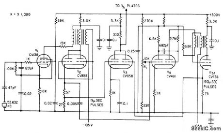
Crystal oscillator V1triggers blocking oscillator V2 to produce sharp pulses at 19.microsec intervals. These feed mono V4, whose output triggers blocking oscillator V5 to give larger pulse every 190 microsec for dud-beam scope of pulse-echo cable fault finder.-F. Jones and J. H. Reyner, Compact New Instrument Finds Undersea Cable Faults, Electronics, 35:37, p 48-50. (View)
View full Circuit Diagram | Comments | Reading(0)
| Pages:104/195 At 20101102103104105106107108109110111112113114115116117118119120Under 20 |
Circuit Categories
power supply circuit
Amplifier Circuit
Basic Circuit
LED and Light Circuit
Sensor Circuit
Signal Processing
Electrical Equipment Circuit
Control Circuit
Remote Control Circuit
A/D-D/A Converter Circuit
Audio Circuit
Measuring and Test Circuit
Communication Circuit
Computer-Related Circuit
555 Circuit
Automotive Circuit
Repairing Circuit