
Signal Processing
Index 100
AMFMAND_SWEEP
Published:2009/7/21 3:17:00 Author:Jessie
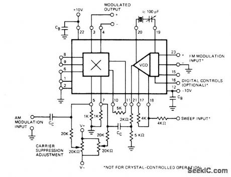
Oscillator and multiplier sections of Exar XR-S200 PLL IC are connected as general-purpose voltage-tuned AM/FM radio-frequency signal generator. Can also serve as high-stability carrier or reference generator if crystal at desired frequency is connected between pins 19 and 20 as shown. Multiplier section introduces amplitude modulation on carrier signal generated by VCO. Balanced multiplier allows suppressed-carrier or double-sideband modulation, Typical carrier suppression is above 40 dB for frequencies up to 10 MHz. With timing capacitor used in place of crystal, oscillator section can provide highly linear FM or frequency sweep. Digital control terminals of oscillator can be used for frequency-shift keying.- Phase-Locked Loop Data Book, Exar Integrated Systems, Sunnyvale, CA, 1978, p 9-16. (View)
View full Circuit Diagram | Comments | Reading(1236)
FIVE_MARKER_STANDARD
Published:2009/7/21 3:53:00 Author:Jessie

Uses 400-kHz DT, cut crystal in NOR-gate oscillator U1A and divider chain U2-U6 to provide calibration markers at 200, 100, 50, 25, 10, and 5 kHz. U2A-U3B are wired as D flip-flops for dividing by 2. U4 is divide by-N counter, with latch arrangement of U5 used to reset selected divide-by5 logic. Out-put of 100 kHz is divided by 5 and then by 2 to give symmetrical 10-kHz output for division by 2 to provide 5 kHz. CM0S CD4000-series logic elements reduce power consumption from 9-V battery to 2.8 mA but allow sufficient switching speed and harmonic energy for good response throughout HF bands.-F. M. Griffee, Frequency-Marker Standard Using CMOS Logic, Ham Radio, Aug. 1977, p 44-45. (View)
View full Circuit Diagram | Comments | Reading(932)
TTL_CRYSTAL_CALIBRATOR
Published:2009/7/21 3:51:00 Author:Jessie

Easily assembled from low-cost TTL digital ICs, for use as troubleshooting signal generator. Almost any frequency can be obtained by correct choice of osdilator crystal and/or division ratio. If zeroed against frequency standard such as WWV, circuit gives accurate frequency check.-J. J. Carr, How to Become a Troubleshooting Wizard, 73 Magazine, Jan, 1976, p138-143. (View)
View full Circuit Diagram | Comments | Reading(856)
20_watt_25_dB_16_to_30_MHz_SSB_linear_amplifiersupply_voltage_is_138_volts
Published:2009/7/21 5:53:00 Author:Jessie
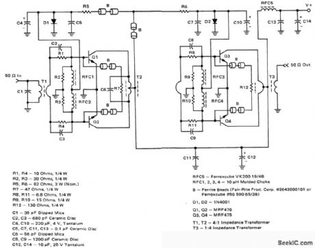
20-watt 25 dB 1.6 to 30 MHz SSB linear amplifier.supply voltage is 13.8 volts (courtesy Motorola semiconductor Products Inc.). (View)
View full Circuit Diagram | Comments | Reading(777)
CMOS_MARKER
Published:2009/7/21 5:30:00 Author:Jessie
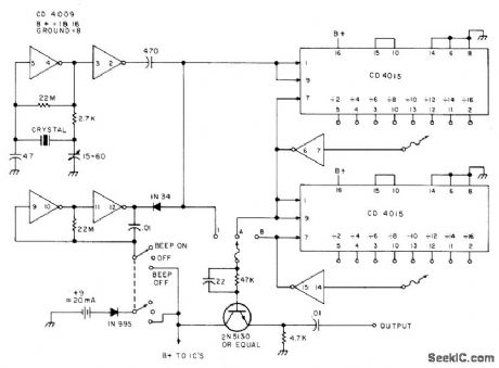
Crystal-controlled marker generator uses any crystal from 100 kHz to 4 MHz. Requires only one CD4009 hex inverter and two CD4015 shift registers. Switches give choice of even. number division ratios up to 256. Used for locating band edges or subbands and for calibrating receivers. Transistor AM beeper is simple clamp that gates RF on or off, to facilitate location of marker in crowded bands.-K.W. Robbins, All Band Frequency Marker, 73 Magazine, June 1975, p 88-90. (View)
View full Circuit Diagram | Comments | Reading(2249)
6_36_MHz_HARMONIC_GENERATOR
Published:2009/7/21 5:00:00 Author:Jessie
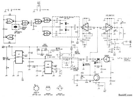
Phase locked loop is used with short-duration pulses from 1-MHz crystal reference oscillator to produce highly accurate harmonics SN74S00N Schottky U2 changes reference wave form to harmonic-rich 100-ns pulses for feed to 1N914 phase-detector diodes CR1 and CR2 Buffer U3 delivers output of 2N5140 VCO to diodes for phase compalison and phase-frequency output is fed to opamp U5 that locks VCO more tightly to reference-oscillator output by increasing its control of varactor, VCO frequency will then be harmoic of reference oscillator Meter used to monitor control voltage to varactor can have full-scale value of 100μA to 1mA, with its multiplier resistor adjusted to read 5 V at midscale.When opamp is capturing VCO, meter needle will flop from side to side but will return to midscale after lock is achieved. Article covers construction, tuning, and operation.-K. W. Robbins and J. R. True, Crystal-Controlled Harmonic Generator, Ham Radio, Nov. 1977, p 66-69. (View)
View full Circuit Diagram | Comments | Reading(1287)
RECEIVER_CHECKER
Published:2009/7/21 4:55:00 Author:Jessie
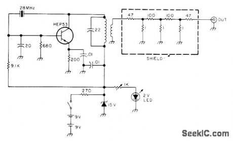
Single-transistor 28-MHz crystal oscillator and carefully designed attenuator network serve to generate signal of about 1μA for checking performance of amateur radio receiver, Can be used on any band down to 6 meters by appropriate choice of crystal and LC circuit components. Coil is CTC LS5 form having 15 turns No. 22 enamel and 2-turn link.-Is It the Band or My Receiver?, 73 Magazine, Oct. 1976, p 132-133. (View)
View full Circuit Diagram | Comments | Reading(745)
Triac_control_circuit_employing_an_ECG776_zero_voltage_switch_with_current_boost_utilizing_an_AC_supply
Published:2009/7/21 4:54:00 Author:Jessie
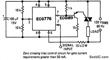
Triac control circuit employing an ECG776 zero voltage switch with current boost utilizing an AC supply. The circuit is for applications requiring gate currents greater than 50 mA. Select the triac from the ECG5600 series for the particular application (courtesy GTE Sylvania Incorporated). (View)
View full Circuit Diagram | Comments | Reading(2639)
100_kHz_CAUBFIATOR
Published:2009/7/21 4:54:00 Author:Jessie
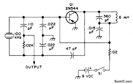
Simple crystal-controlled single-transistor oscillator can be used to calibrate amateur radio transceiver. Output should be connected to antenna input side of receiver, not to antenna terminal normally used.-Novice Q & A, 73Magazine, March 1977, p 187. (View)
View full Circuit Diagram | Comments | Reading(746)
PULSED_MARKER
Published:2009/7/21 5:34:00 Author:Jessie
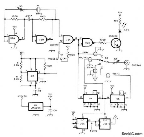
Crystal calibrator circuit provides pulsed output for easy spotting, eliminating need for turning marker on and off repeatedly to identify it in crowded band. With values shown, switching rate is about 2 Hz. When marker is found, placing S1 in CW position keeps it on for zero-beating calibrator output more accurately. Reducing value of C1 increases switching speed of U3, thus increasing pulse rate. LED indicates either pulsed or CW output. ICs are conventional types used in crystal calibrators.-R. G. Brunner, Crystal Calibrator Has Pulsed Output, QST, Nov. 1977, p 45. (View)
View full Circuit Diagram | Comments | Reading(869)
50_MHz_WITH_ATTEN_UATOR
Published:2009/7/21 5:33:00 Author:Jessie
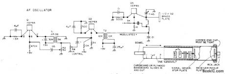
Positioning of miniaturized signal generator in 4 1/2 x 2 1/8 x 24 inch waveguide provides stable variable-strength signal that can be dropped gradually down to zero as generator is moved away from receiver pickup plate. Slide can be calibrated for measuring sensitivity of 6-meter receiver in tenths of a microvolt. Circuit consists of 50-MHz crystal oscillator, AF oscillator and simple class A modulator.-B, Hoisington, Low-Cost Infinite Attenuator for Amateur Use, 73 Magazine,Sept 1974,p107-108. (View)
View full Circuit Diagram | Comments | Reading(723)
5_MHz_STAN_DARD
Published:2009/7/21 5:32:00 Author:Jessie
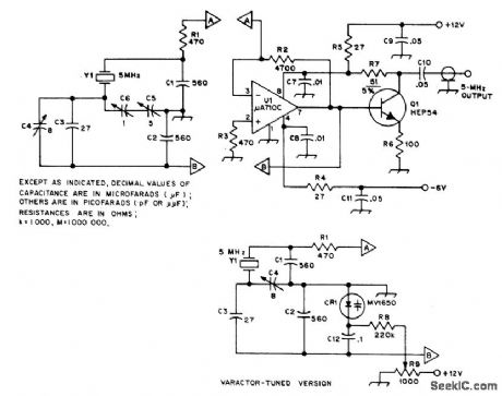
Guriot-Clapp crystal oscillator using broadband high-gain opamp U1 can be tuned by conventional variable capacitor C5 or alternatively by Motorola MV1650 varactor CR1. Buffer Q1 minimizes effect of loading on frequency.-R. Silberstein, An Experimental Frequency Standard Using ICs, QST, Sept. 1974, p 14-21 and 167. (View)
View full Circuit Diagram | Comments | Reading(626)
160_MC_15_W_POWER_AMPLIFIER
Published:2009/7/21 7:38:00 Author:Jessie
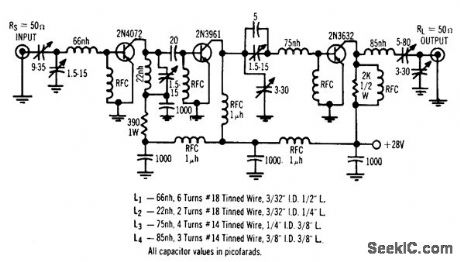
Simple three-stage r-f power transistor circuit provides 30.5 db power gain with efficiency of 62%, on 28-v supply.-Solid-State Power Amplifier Design (Motorola ad), Electronics, 39:14, p 48-49. (View)
View full Circuit Diagram | Comments | Reading(1)
TUNNEL_DIODE_WIRELESS_MIKE
Published:2009/7/21 7:36:00 Author:Jessie
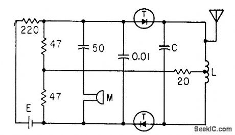
Two cascaded 2-ma germanium tunnel diodes serving as cascade oscillator and 90-Mc f-m modulator give range of over 100 feet. Coil L is about 5 microhenrys, with five turns a quarter-inch in diameter and half an inch long.C is 24 pf.-W. Ko, Tunnel Diode F.M Wireless Microphone, Electronics, 33:47, p 93-95. (View)
View full Circuit Diagram | Comments | Reading(1325)
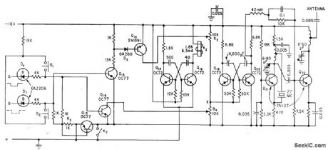
MEASURING_ANTENNA_RADIATION_PATTERN
Published:2009/7/21 7:35:00 Author:Jessie
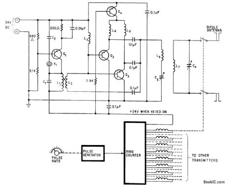
Eight transmitters, towed as group around ground antenna by airplane, hove frequencies spaced throughout bandwidth of antenna under test, from 2 to 50 Mc. Pulse-controlled ring counter switches transmitters up to 40 times per second. All transistors are type 2N3053.-C. Barnes, Transmitters Towed Through Air Test Antenna's Radiation Pattern, Electronics, 38:21, p 96-101.
(View)
View full Circuit Diagram | Comments | Reading(1001)
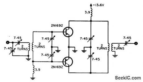
PARALLEL_TRANSISTOR_OUTPUT_STAGE_WITH_EMITTER_TUNING
Published:2009/7/21 7:07:00 Author:Jessie

Variable capacitor common to both emitters, together with r-f choke for d-c path, Provides efficient tuning and increased power gain at outputs near maximum of 2 w. Chief drawback is reduced Power gain at low input levels,-W.A. Rheinfelder, choosing the Best Transmitter Output Stage,EEE,11:10,p 48-53. (View)
View full Circuit Diagram | Comments | Reading(852)
10_W_AT_50_MC
Published:2009/7/21 7:06:00 Author:Jessie
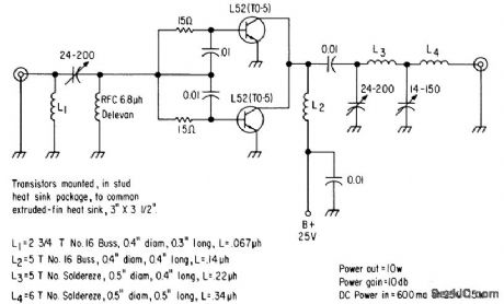
Two L52's in parallel provide 10 w output power with 10 db gain. Separate biasing resistors are used in base circuits to balance operating currents. Input and output impedances are both 50 ohms, and overall efficiency is 65%.-Texos Instruments Inc., Solid-State Communications, McGraw-Hill, N.Y., 1966, p 323. (View)
View full Circuit Diagram | Comments | Reading(696)
18_19_MHz_VFO
Published:2009/7/8 2:15:00 Author:May
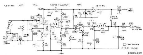

Series-tuned Clapp oscilla-torusing high-impedance JFET at has good fre-quency stability. Diode stabilizes bias. Air variable C1 provides frequency spread of exactly 100 kHz. L1 is 25-58 μH slug-tuned (Miller 43A475CBI). L2 is 10-18.7 μH slug-tuned (Miller 23A155RPC).—D. DeMaw, More Basics on Solid-State Transmitter Design, OST, Nov.1974, p 22-26 and 34. (View)
View full Circuit Diagram | Comments | Reading(1230)
LOW_POWER_PUSH_PULL_OUTPUT
Published:2009/7/21 7:44:00 Author:Jessie
Efficiency is higher than with normal parallel output stage, yet overall efficiency is only 48% for 1.9-w output because emitter tuning is not effective and power gain is accordingly reduced.-W. A. Rheinfelder, Choosing the Best Transmitter Output State, EEE, 11:10, p 48-53. (View)
View full Circuit Diagram | Comments | Reading(761)
27_MC_REMOTE_EVENT_TRANSMITTER
Published:2009/7/21 7:41:00 Author:Jessie
Gives 400-cps modulation for pulse at input A,1,400 cps for pulse at B, and 800-cps check pulses every 2 sec, for transmitting bird nigh! data to remote recorder.-P. A. Tove and J. Czekaiewski, Infrared Curtain System Detects and Counts Moving Objects, Electronics, 34:31, p 40-43. (View)
View full Circuit Diagram | Comments | Reading(701)
| Pages:100/195 At 2081828384858687888990919293949596979899100Under 20 |
Circuit Categories
power supply circuit
Amplifier Circuit
Basic Circuit
LED and Light Circuit
Sensor Circuit
Signal Processing
Electrical Equipment Circuit
Control Circuit
Remote Control Circuit
A/D-D/A Converter Circuit
Audio Circuit
Measuring and Test Circuit
Communication Circuit
Computer-Related Circuit
555 Circuit
Automotive Circuit
Repairing Circuit