
Signal Processing
Index 90
The medical electric aspirator waterproof controller (1)
Published:2011/7/21 19:55:00 Author:qqtang | Keyword: aspirator, waterproof controller
The working principle of the circuit
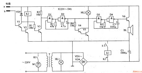
The medical electric aspirator waterproof controller circuit consists of the power supply circuit, liquid level detection control circuit and acousto-optical alarm circuit, see as figure 9-46.
The power supply circuit consists of the transformer T, power supply indicator HL1, rectifier diode VDl-VD4 and filter capacitor C1. The liquid level controller circuit consists of the detection poles a and b(inserted in the bottleneck of the liquid bottle), transistors V1 and V2, diode VD5, relays of K1 and K2 and the step switch S.
(View)
View full Circuit Diagram | Comments | Reading(771)
The medical constant temperature box (1)
Published:2011/7/21 20:02:00 Author:qqtang | Keyword: constant temperature box
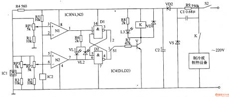
Here is to introduce a medical constant temperature box which is fixed with the temperature sensor integrated circuit, and the temperature control range is -25-+100℃.The working principle of the circuitThe medical constant temperature box consists of the temperature detection amplifier circuit, trigger, control circuit and power supply circuit, see as figure 9-40.
The temperature amplifier circuit consists of the precise regulated integrated circuit IC1, temperature sensor integrated circuit IC2, computing amplifier integrated circuit IC3 (N1 and N2), resistor R1-R5 and resistors RP1 and RP2. (View)
View full Circuit Diagram | Comments | Reading(1280)
The frequency spectrum therapeutic apparatus
Published:2011/7/21 20:11:00 Author:qqtang | Keyword: frequency spectrum, therapeutic apparatus
The working principle of the circuit
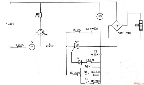
This frequency spectrum therapeutic apparatus consists of the power supply circuit, control circuit and frequency spectrum generator, see as figure 9-28.
The power supply circuit consists of the resistor R1-R5, switch S1-S3, dual-way trigger diode V, thyristor VT, capacitors C1 and C2, etc. The frequency spectrum generator consists of the voltmeter PV, rectifier VD1-VD4 and frequency spectrum heater EH. (View)
View full Circuit Diagram | Comments | Reading(636)
The FET therapeutic apparatus
Published:2011/7/21 20:30:00 Author:qqtang | Keyword: FET, therapeutic apparatus
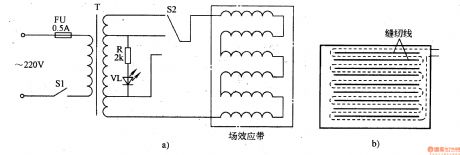
The working principle of the circuitThe FET therapeutic apparatus is simple, which consists of the fuse FU, power supply transformer T, power supply switch S1, voltage regulation switch S2, current limit resistor R, power supply indicator LED VL and FET band, see as figure 9-26.
When the power is on, its indicator VL is glowing. At the same time, there generates a inducting voltage on the secondary coil of the transformer T. The core voltage is added on the FET band, which generates the alternating field, eddy field and infrared rays. (View)
View full Circuit Diagram | Comments | Reading(577)
The electromagnet therapeutic apparatus (2)
Published:2011/7/21 20:36:00 Author:qqtang | Keyword: electromagnet, therapeutic apparatus
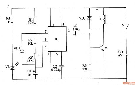
The working principle of the circuit This electromagnet therapeutic apparatus consists of the ultra-low-frequency oscillator, magnetic pulse generator circuit and power supply circuit, see as figure 9-14.
The ultra-low-frequency oscillator circuit consists of the time-based integrated circuit, resistors R1 and R2, potentiometers C1 and C2, diode VD1 and so on. The magnetic pulse generator circuit consists of the resistor R3, transistor V, diode VD2 and electromagnet coil L. (View)
View full Circuit Diagram | Comments | Reading(2076)
The boiler electric cleaner
Published:2011/7/22 5:31:00 Author:qqtang | Keyword: electric cleaner
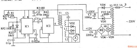
The boiler electric cleaner of the example is to process the water with high frequency electric field, so the physical characters of the minerals in the water are changed, so the dirt is removed or avoided. The working principle of the circuitThe boiler electric cleaner circuit consists of the power supply circuit, 200khz rectangular wave oscillator, drive amplifier circuit and output indicating circuit and so on, see as figure 8-153.
The power supply circuit consists of the transformer TV, rectifier diode VD4-VD9, filter capacitors of C5 and C6, etc. (View)
View full Circuit Diagram | Comments | Reading(676)
The 3-phase AC constant phase sequence controller
Published:2011/7/22 5:39:00 Author:qqtang | Keyword: phase sequence controller, 3-phase
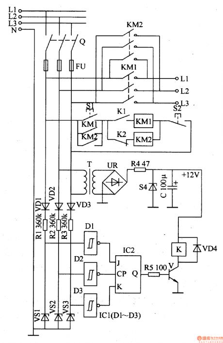
The working principle of the circuitThe working principle of the circuit consists of the the power supply circuit, phase sequence detecting circuit and control circuit, see as figure 8-152.
The power supply circuit consists of the transformer T, rectifier bridge pile UR, resistor R4, regulated diode VS4 and filter capacitor C.The phase sequence detecting circuit consists of the rectifier diode VD1-VD3, current limit resistor R1-R3, regulated diode VS1-VS3 and D1-D3 in IC1 of the NOR gate Schmidt trigger integrated circuit. (View)
View full Circuit Diagram | Comments | Reading(2525)
The industrial X ray defect detector time delay control switch
Published:2011/7/22 5:46:00 Author:qqtang | Keyword: X ray, defect detector, time delay

The working principle of the circuit The industrial X ray defect detector time delay control switch circuit consists of the regulated filter circuit, time delay control circuit A, delay control circuit B and control executing circuit, see as figure 8-150.
The regulated filter circuit consists of the capacitors of C5 and C6 and the 3-phase regulated integrated circuit IC3. The time delay control circuit A consists of the resistor R1-R3, capacitors of C1 and C2, time-based integrated circuit IC1, diode VD1, relay K1, LED diode VL1 and control key S1. (View)
View full Circuit Diagram | Comments | Reading(1494)
RUN_DOWN_CLOCK_SOUND_GENERATOR
Published:2009/7/9 4:39:00 Author:May
Used in electronic roulette or dice games, this circuit produces a clock signal that initially is several tens of kHz (depending on C2) and gradually decreases to zero in about 15 seconds, as C1 discharges through R4. (View)
View full Circuit Diagram | Comments | Reading(1048)
CAPACITOR_DISCHARGE_HIGH_VOLTAGE_GENERATOR
Published:2009/7/9 4:36:00 Author:May
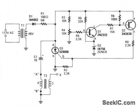
Stepdown transformer T1 drops the incoming line voltage to approximately 48 Vac which is rectified by diode D1; the resultant dc charges capacitor C1-through current limiting resistor R1-to a volt-age level preset by R4. When the voltage on R4's wiper reaches about 8.6 V, Q1 begins to turn on, drawing current through R7 and the base-emitter junction of Q2. Q2 turns on and supplies a positive voltage to the gate of silicon-controlled rectifier Q3. The positive gate voltage causes Q3 to conduct, thereby discharging C1 through the primary winding of step-up transformer T2, which results in a high-voltage arc at output terminal X. The voltage developed at T2's output is determined by the value of C1, the voltage across Q1, and the turns ratio of transformer T2. The frequency or pulse rate of the high voltage is determined by the resis-tance of T1's primary and secondary windings, the value of R1, and the value of C1. The lower the value of each item, the higher the output pulse rate ; the peak output voltage will only remain unchanged if C1's value remains unchanged. (View)
View full Circuit Diagram | Comments | Reading(817)
BATTERY_POWERED_HIGH_VOLTAGE_GENERATOR
Published:2009/7/9 4:17:00 Author:May

Output voltage great enough to jump a 1-inch gap can be obtained from a 12-V power source. A 555 timer IC is connected as an astable multivibrator that produces a narrow negative pulse at pin 3. The pulse turns Q1 on for the duration of the time period. The collector of Q1 is direct-coupled to the base of the power transistor Q2, turning it on during the same time period. The emitter of Q2 is direct-coupled through current limiting resistor R5 to the base of the power transistor. Q3 switches on, producing a minimum resistance between the collector and emitter. The high-current pulse going through the primary of high-voltage transformer T1 generates a very high pulse voltage at its secondary output terminal (labeled X). The pulse frequency is determined by the values of R1, R2, and C2. The values given in the parts list were chosen to give the best possible performance when an auto-ignition coil is used for T1. (View)
View full Circuit Diagram | Comments | Reading(1197)
HIGH_VOLTAGE_DC_GENERATOR
Published:2009/7/9 4:14:00 Author:May
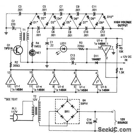
This circuit is fed from a 12-Vdc power supply.The input to the circuit is then amplified to providea 10, 000-Vdc output.The output of the up-converter is then fed into a 10 stage, high-voltage multiplier to produce an output of 10, 000 Vdc. (View)
View full Circuit Diagram | Comments | Reading(0)
SIMPLE_VCO
Published:2009/7/9 4:12:00 Author:May
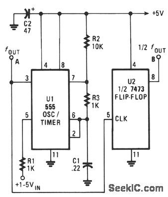
The output frequency of the VCO, U1, vanes inversely with the input voltage. With a 1-V input, the oscillator output frequency is about 1500 Hz; with a 5-V input, the output frequency drops to around 300 Hz. The output frequency range of U1 can be altered by varying the values of C1, R2, and R3. Increasing the value of any those three components will lower the oscillator frequency, and decreasing any of those values will raise the frequency. Output-waveform symmetry suffers since the frequency varies from one extreme to the other. At the highest frequency, the waveform is almost equally divided. But when the frequency drops, the output of the circuit turns into a narrow pulse. If a symmetrical waveform is required, add the second IC, U2, half of a 7473P dual TTL J-K flip-flop, to the oscillator circuit. The signal frequency output by U2 is 1/2 of the input. (View)
View full Circuit Diagram | Comments | Reading(1064)
WHITE_NOISE_GENERATOR
Published:2009/7/9 4:10:00 Author:May
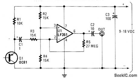
Germanium transistor Q1 is used as a noise generator in the audio range. U1 acts as a high-gain ampli-fter. Q1 is not critical; most germanium transistors appear to be satisfactory. A germanium diode can also be substituted. This circuit is mainly used for sound effects and noise experiments. It is not flat over the audio range because of unpredictable effects in Q1, but it should be useful where high precision is not necessary. (View)
View full Circuit Diagram | Comments | Reading(0)
VCO
Published:2009/7/9 4:08:00 Author:May

At startup, the voltage in the trigger input at pin 2 is less than the trigger level voltage, 1/3 VDD, causing the timer to be triggered via pin 2. The output of the timer at pin 3 becomes high, allowing capacitor Ct to charge very rapidly through diode D1 and resistor R1.When capacitor Ct charges to the upper threshold voltage 2/3 VDD, the flip-flop is reset, the output at pin 3 decreases, and capacitor Ct discharges through the current mirror, TL011. When the voltage at pin 2 reaches 1/3 VDD, the lower threshold or trigger level, the timer triggers again and the cycle is repeated. (View)
View full Circuit Diagram | Comments | Reading(1418)
FM_GENERATOR
Published:2009/7/9 4:03:00 Author:May
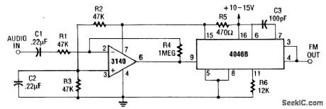
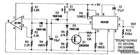
The internal zener on pin 15 of the 4046B supplies a stable voltage to the 3140lC op amp. This ampli-fter modulates the 4046B VCO. The amplifier gain is about 20x (26 dB voltage). The VCO produces a 220-kHz carrier that is FM modulated. C3 can be changed to vary this frequency. (View)
View full Circuit Diagram | Comments | Reading(1592)
LOGARITHMIC_SWEEP_VCO
Published:2009/7/9 3:58:00 Author:May
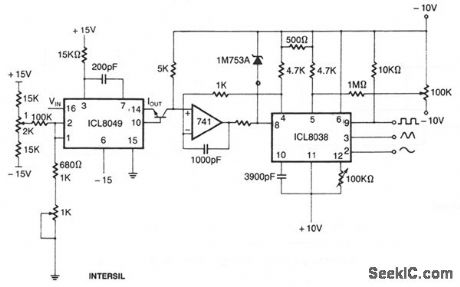
This circuit uses the output of the ICL8049 to control the frequency of the ICL3038 waveform genera-tor; the 741 op amp is used to linearize the voltage-frequency response. The input voltage to the 8049 can be, for example, from the horizontal sweep signal of an oscilloscope; the output of the 8038 will then sweep logarithmically across the audio range. By feeding this to the equipment being measured and detecting the output, a standard frequency response can be obtained. If the output is fed through an ICL8048 before being displayed, a standard bode plot results. (View)
View full Circuit Diagram | Comments | Reading(2155)
FUNCTION_GENERATOR
Published:2009/7/9 3:56:00 Author:May
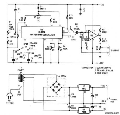
Using an Intersil ICL8038, this function generator generates frequencies from 1 Hz to over 80 kHz.R1 is the fine frequency control and S1 is the coarse frequency control range switch. S2 selects square-, triangle-, or sine-wave output. U2 is a buffer amplifier and R5 sets output level. R2 is adjusted for a sym-metrical triangle wave. R3 and R4 are adjusted for minimum sine-wave distortion. Power supply is ±12 V at less than 100 mA. (View)
View full Circuit Diagram | Comments | Reading(0)
VARIABLE-CAPACITANCE_DIODE_SPARKED_VCO
Published:2009/7/9 3:52:00 Author:May
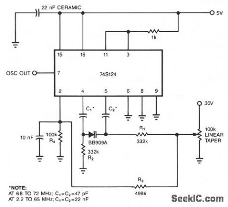
You can transform a 741S124 multivibrator into a wideband VCO by replacing it conventional ftxed capacitor with a variable-capacitance diode. The only disadvantage of this scheme is the 30-V biasing volt-age that the diode requires. Capacitors C1 and C2 couple the Philips BB909A variable-capacitance diode to the 74S124. R1 and R2 are large enough to isolate ground and control voltages from the timing capacitors. Resistors R3 and R4 form a voltage divider for the 74S124's control input. (View)
View full Circuit Diagram | Comments | Reading(1223)
AUDIO_FUNCTION_GENERATOR
Published:2009/7/9 3:51:00 Author:May
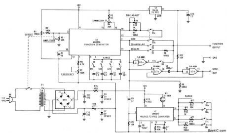
Using an EXAR XR2206, this generator will produce sine, square, and triangular waves from 10 Hz to 100 kHz. U1 is the XR2206 chip, R7 controls frequency, and 55 through 58 select the frequency range. U3 produces a TTL-compatible square-wave output, while U3C and D produce a sync signal for scope use. U2 is a frequency/voltage converter that is used to drive analog meter M1, which reads the generator frequency. (View)
View full Circuit Diagram | Comments | Reading(7783)
| Pages:90/195 At 2081828384858687888990919293949596979899100Under 20 |
Circuit Categories
power supply circuit
Amplifier Circuit
Basic Circuit
LED and Light Circuit
Sensor Circuit
Signal Processing
Electrical Equipment Circuit
Control Circuit
Remote Control Circuit
A/D-D/A Converter Circuit
Audio Circuit
Measuring and Test Circuit
Communication Circuit
Computer-Related Circuit
555 Circuit
Automotive Circuit
Repairing Circuit