
Signal Processing
Index 88
471_MC_TUNNEL_DIODE_CRYSTAL_OSCILLATOR
Published:2009/7/20 2:04:00 Author:Jessie
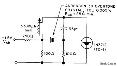
Used in Fire Department service. 0perates within tolerance of quartz crystal from -55 to +85℃ and bias range of 110 to 150 mv for Citizens Band service.- Transistor Manual, Seventh Edition, General Electric Co., 1964, p 353. (View)
View full Circuit Diagram | Comments | Reading(1174)
CRYSTAL_OR_CAPACITOR_OSCILLATOR
Published:2009/7/20 2:02:00 Author:Jessie
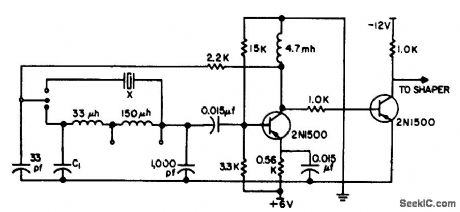
Gives high stability from 800 kc to 3 Mc, from 0 to 65℃ with either crystal or capacitor. Optimum operating frequency can be found and utilized by changing capacitor value C1 in range up to 500 pf, while awaiting delivery of CT-cut crystal at desired frequency. -T. Asai, Crystal-or-capacitor Oscillator, EEE, 12:3, p 72. (View)
View full Circuit Diagram | Comments | Reading(864)
SINE_WAVE_TUNNEL_DIODE
Published:2009/7/20 2:01:00 Author:Jessie
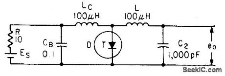
Low-impedance capacitor in parallel with sefies-resonant circuit of tunnel-diode relaxation oscillator passes all frequencies except that for series resonance, giving sinusoidal voltage across output capacitor. Output frequency varies from Q1 to 0.8 Mc over bias range of 000 to 400 mv.-Wen-Hsiung Ko, Designing Tunnel Diode Oscillators, Electronics, 34:6, p 68-72. (View)
View full Circuit Diagram | Comments | Reading(1283)
100_MC_COLPITTS
Published:2009/7/20 2:00:00 Author:Jessie
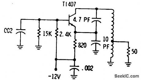
Uses conventional bipolar transistor, which has low noise in operation from low-impedance voltage generator. Temperature drift is much greater than with fet. -Fets Come Alive: Clinic Unveils Practical Circuits, EEE, 14:4, p 16-18. (View)
View full Circuit Diagram | Comments | Reading(827)
SIREN_WARBLE_GENERAIOR
Published:2009/7/9 23:18:00 Author:May

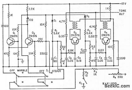
Genemtes singletone and wcrble signals. Blocking oscillators Q3 and Q4, having slightly different frequendes, are frequency-modulated by triangular-wave output of low-frequency mvbr Q1-Q2, to produce siren-type wail.-W. F. Ferguson, High-Powered Audio Alarm Systems, Eleeronics, 33:16, p 70-72. (View)
View full Circuit Diagram | Comments | Reading(789)
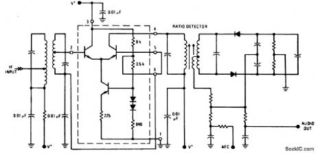
FM_ratio_detector_circuit
Published:2009/7/20 2:39:00 Author:Jessie
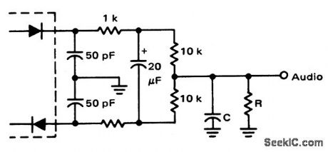
FM ratio detector circuit. With R equal to 22K and C equal to 100 pF the roll off occurs at about 70 kHz (courtesy Motorola Semiconductor Products Inc.). (View)
View full Circuit Diagram | Comments | Reading(2280)
4_channel_SQ_logic_decoder
Published:2009/7/20 2:38:00 Author:Jessie
4-channel SQ logic decoder. Current drain at 20 volts is 60 mA. Input impedance is 2M. Output impedance is 2K (courtesy GTE Sylvania Incorporated). (View)
View full Circuit Diagram | Comments | Reading(693)
FM_IF_amplifier_using_two_MC1355_chips
Published:2009/7/20 2:37:00 Author:Jessie
FM IF amplifier using two MC1355 chips. Two TRW phase linear five-pole 10.7 MHz filters provide a combined 240 kHz bandwidth (courtesy Motorola Semiconductor Products Inc.). (View)
View full Circuit Diagram | Comments | Reading(1150)
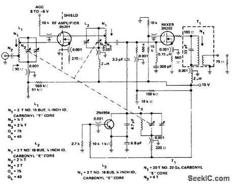
AM_broadcast_tuner_with_RF_amplifier_for_automobile_applicatio
Published:2009/7/20 2:44:00 Author:Jessie
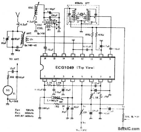
AM broadcast tuner with RF amplifier for automobile application. Audio output is 80 mV with 400-hertz modulation at 30%. The IF is 455 kHz. All coils and transformers are standard and can be purchased at Radio Shack (courtesy GTE Sylvania Incorporated). (View)
View full Circuit Diagram | Comments | Reading(798)
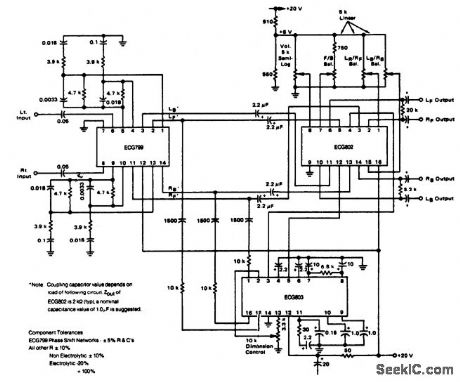
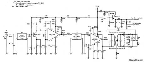
FM_IF_amplifier_and_discriminator_for_107_MHz_using_an_ECG760_Gain_is_typically_40_dB_at_107_MHz
Published:2009/7/20 2:43:00 Author:Jessie
FM IF amplifier and discriminator for 10.7 MHz using an ECG760(enclosed in dashed lines)Gain is typically 40 dB at 10.7 MHz. Power supply voltage should be 20 volts(courtesy GTE Sylvania Incorporated). (View)
View full Circuit Diagram | Comments | Reading(668)
4_channel_SQ_logic_decoder_1
Published:2009/7/20 2:42:00 Author:Jessie

4-channel SQ logic decoder. Current drain is 75 mA at 20 volts. Input impedance is 2M, while output impedance is 2K (courtesy GTE Sylvania Incorporated). (View)
View full Circuit Diagram | Comments | Reading(717)
107_MHz_FM_IF_amplifier_and_detector_using_four_ECG1104_5_pin_modules
Published:2009/7/20 2:40:00 Author:Jessie

10.7 MHz FM IF amplifier and detector using four ECG1104 5-pin modules. Coil data and specifications also are shown (courtesy GTE Sylvania Incorporated). (View)
View full Circuit Diagram | Comments | Reading(620)
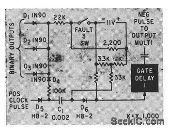
The thickness of the paper detector
Published:2011/7/21 22:30:00 Author:qqtang | Keyword: detector, thickness
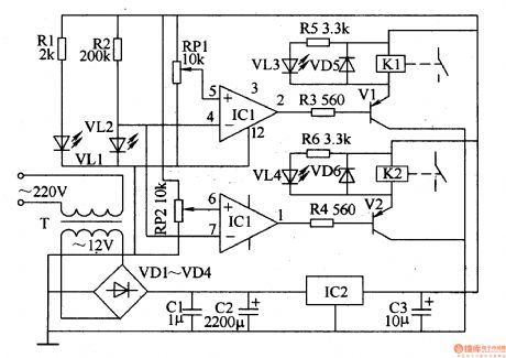
The working principle of the circuitThe thickness of the paper detector circuit consists of the power supply circuit, infrared detection circuit and control executing circuit, see as figure 8-143.
The power supply circuit consists of the power supply transformer T, rectifier diode VD1-VD4, filter capacitor C1-C3 and 3-terminal regulator IC2 and so on.The AC 220V current is stepped down by T, rectified by VD1-VD4, stabilized by IC2 and filtered by C1-C3, then it becomes a 12V DC voltage and it is provided for the infrared detection circuit and control executing circuit.
(View)
View full Circuit Diagram | Comments | Reading(1020)
FET_HARTLEY
Published:2009/7/20 1:59:00 Author:Jessie
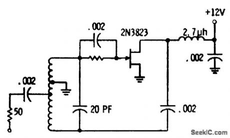
Delivers 680 mv to 50-ohm load at 100 Mc. Coil is four 3/8-inch-diameter turns of No. 16 wire spaced to 0.5 inch.-Fets Come Alive: Clinic Unveils Practical Circuits, EEE, 14:4, p 16-18. (View)
View full Circuit Diagram | Comments | Reading(955)
AM_FM_stereo_tuner
Published:2009/7/20 2:58:00 Author:Jessie
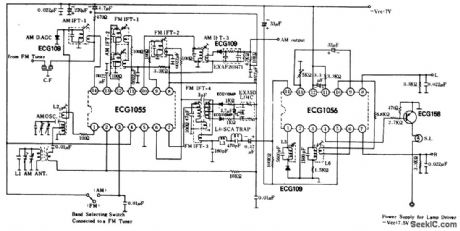
AM/FM stereo tuner. Both ICs are 14-pin DIPs. The ECG1055 is an AM/FM IF amplifier and AM converter, while the ECG1056 is a stereo multiplex demodulator with a composite amplifier, 19 kHz pilot signal filter, a 38 kHz subcarrier generator and either a matix or switching circuit for left and right stereo audio channels (courtesy GTE Sylvania Incorporated). (View)
View full Circuit Diagram | Comments | Reading(1943)
FM_stereo_demodulator_with_integral_Stereo_monaural_switch_75_mA_lamp_driving_capability
Published:2009/7/20 2:54:00 Author:Jessie
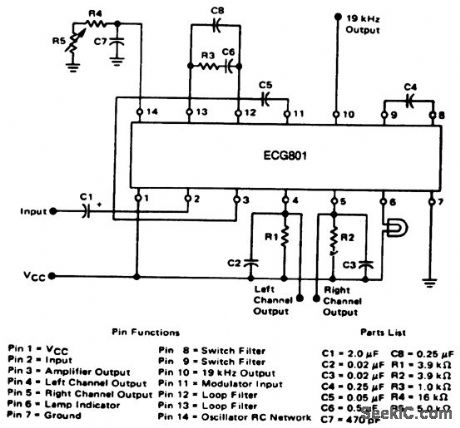
FM stereo demodulator with integral Stereo/monaural switch 75 mA lamp driving capability.Typical supply voltag;is 12 volts but can be operated between 8 and 14 volts. Alignment is simple since there is only one adjustment,R5.Adjust R5 until 19 kHz is read at pin 10 on a frequency counter(courtesy GIE Sylvania Incorporated). (View)
View full Circuit Diagram | Comments | Reading(629)
FM_tuner_front_end_using_dual_gate_MOSFETs
Published:2009/7/20 3:28:00 Author:Jessie
FM tuner front end using dual-gate MOSFETs (courtesy Texas Instruments Incorporated). (View)
View full Circuit Diagram | Comments | Reading(3895)
Complete_AM_FM_broadcast_receiver_with_1_watt_output_and_powered_by_6_volts
Published:2009/7/20 3:27:00 Author:Jessie

Complete AM/FM broadcast receiver with 1-watt output and powered by 6 volts.All coils and transformers are standard and can be purchased at Radio Shack.FM sensitivity is 1 μV,while AM is 30 μv(courtesy GTE Sylvania Incorporated). (View)
View full Circuit Diagram | Comments | Reading(881)
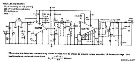
Complete_limiting_FM_IF_amplifier_and_detector
Published:2009/7/20 3:25:00 Author:Jessie

Complete limiting FM IF amplifier and detector.Typical AM rejection is 60dB,ECG746 is an 8-pin DIP and ECG750 is a 14-pin DIP.The ECG750 is designed for use with a Foster-Seeley discriminator or radio detector.Transformer T1 is a 10.7 MHz Foster-Seeley discriminator with a primary impedance of 3.9K and a peak-to-peak separation of 600 kHz. The discriminator diodes are ECG110MP(courtesy GTE Sylvania Incorporated). (View)
View full Circuit Diagram | Comments | Reading(1243)
FM_IF_amplifier_with_quadrature_detector
Published:2009/7/20 3:23:00 Author:Jessie
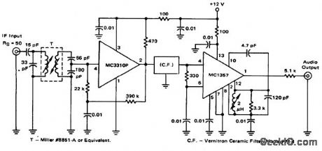
FM IF amplifier with quadrature detector (courtesy Motorola Semiconductor Products Inc.). (View)
View full Circuit Diagram | Comments | Reading(1076)
| Pages:88/195 At 2081828384858687888990919293949596979899100Under 20 |
Circuit Categories
power supply circuit
Amplifier Circuit
Basic Circuit
LED and Light Circuit
Sensor Circuit
Signal Processing
Electrical Equipment Circuit
Control Circuit
Remote Control Circuit
A/D-D/A Converter Circuit
Audio Circuit
Measuring and Test Circuit
Communication Circuit
Computer-Related Circuit
555 Circuit
Automotive Circuit
Repairing Circuit