
Signal Processing
Index 84
FM_IF_gain_block_shown_connected_to_typical_FM_receiver_circuitry
Published:2009/7/19 23:02:00 Author:Jessie
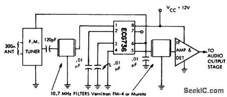
FM IF gain block shown connected to typical FM receiver circuitry. The IF amplifier and detector chip can be an ECG708, for example (courtesy GTE Sylvania Incorporated). (View)
View full Circuit Diagram | Comments | Reading(583)
TONE_OPERATED_CALLING_SYSTEM
Published:2009/7/19 23:02:00 Author:Jessie
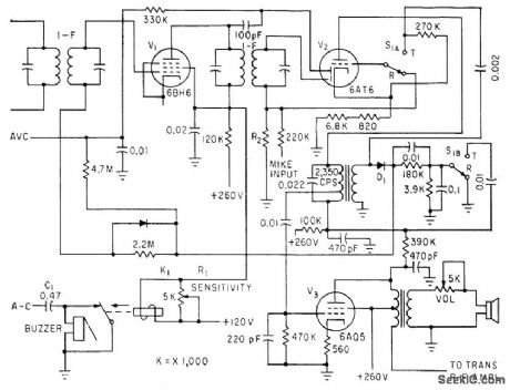
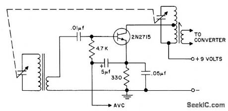
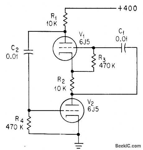
Calling frequency of 2,350 cps is amplified by plate resonant circuit of V2. D1 rectifies this signal and applies positive-going voltage to control grid of last i-f V1,to operate K1 and sound buzzer.-L. Solomon, Citizens Band Equipment Design, Electronics, 33:45, p 70-72. (View)
View full Circuit Diagram | Comments | Reading(630)
MEASURING_OSCILLATOR_STABILITY
Published:2009/7/19 23:02:00 Author:Jessie
Circuit is used as 90.3125-Mc reference oscillator in system for measuring short-term stability of 45-Mc stalo (stable local oscillator) of airborne radar under high vibration. Tape transformer in collector circuit of transistor controls crystal drive.-J. Coolican, How to Measure STALO Short-Term Stability Under Vibration, EEE, 13:5, p 96-98. (View)
View full Circuit Diagram | Comments | Reading(1008)
VOLTAGE_CONTROLLED_23_MC_OSCILLATOR_AND_MODULATOR
Published:2009/7/19 23:01:00 Author:Jessie
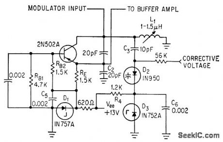
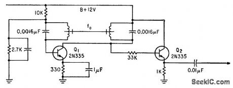
Input signal voltage to transistor changes capacitance of tank circuit, to make oscillator frequency vary with input signal voltage. Variable-capacitance diode requires fewer parts than transistor modulator. Zener diodes provide constant bias for variable-capacitance diode D2.-F. L. Carroll, How to Achieve Stability in Space Telemetry, Electronics, 37:4, p 32-35. (View)
View full Circuit Diagram | Comments | Reading(753)
FM_stereo_processor_3
Published:2009/7/19 23:01:00 Author:Jessie
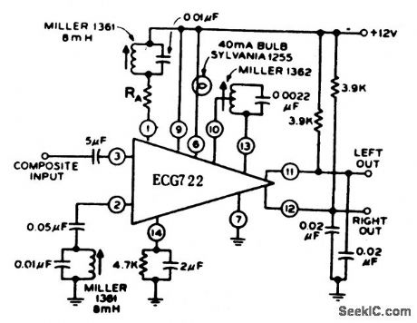
FM stereo processor. The 1 4-pin ECG722 perform the standard stereo functions of 19 kHz amplifier, frequency doubler, stereo indicator lamp driver, and stereo demodulator. Current drain at 12 volts is typically 14 mA (courtesy GTE Sylvania Incorporated). (View)
View full Circuit Diagram | Comments | Reading(631)
BEAT_FREQUENCY_AUDIO_GENERATOR
Published:2009/7/10 2:27:00 Author:May
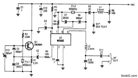
Q1 is a fixed oscillator operating at 455 kHz. U1 is a mixer, with its own internal oscillator running at 455 kHz. FIL1 and FIL2 are Murata CSB455E filters or equivalent. D1 is a vat-actor diode (an IN4002 used as a varactor works well here). R6 controls the bias on D1. When R6 is varied, the oscillator fre-quency varies a few kHz. Audio beat note is taken, through RF filter L2 and C10, from pin 5 of U1.
(View)
View full Circuit Diagram | Comments | Reading(1658)
TUNED_R_F_STAGE
Published:2009/7/19 23:00:00 Author:Jessie
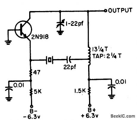
Improves sensitivity, selectivity, and signal-to-noise ratio when used at input of radio receiver.- Transistor Manual, Seventh Edition, General Electric Co., 1964, p 283. (View)
View full Circuit Diagram | Comments | Reading(719)
FM_stereo_processor_2
Published:2009/7/19 23:00:00 Author:Jessie
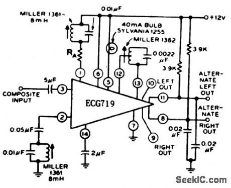
FM stereo processor. The 14-pin DIP performs the standard stereo functions of 19 kHz amplifier, frequency doubler, stereo indicator lamp driver, and stereo demodulator. The l0 also includes two alternate emitter follower outputs (courtesy GTE Sylvania Incorporated). (View)
View full Circuit Diagram | Comments | Reading(624)
FREE_RUNNING_CASCODE_OSCILLATOR
Published:2009/7/19 22:59:00 Author:Jessie
Omission of voltage-divider capacitors from cascode multivibrator gives sine-wave oscillator if loop gain is equal to unity.-C. Sing, Advantages of Free-Running Cascode Multivibrators, Electronics, 37:5, p 28-29. (View)
View full Circuit Diagram | Comments | Reading(748)
FM_stereo_processor
Published:2009/7/19 22:58:00 Author:Jessie
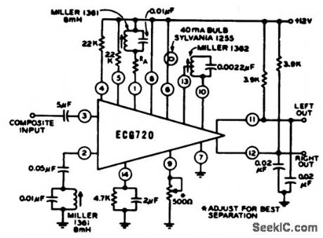
FM stereo processor. Supply voltage is typically +12 volts. The ECG720 has the functions of a 19 kHz amplifier, frequency doubter, stereo indicator lamp driver, audio mute, stereo/mono switch, and stereo demodulator. it also permits adjust-able stereo channel separation (courtesy GTE Sylvania Incorporated). (View)
View full Circuit Diagram | Comments | Reading(0)
100_KC_MAGNETOSTRICTIVE_ROD_CONTROL_
Published:2009/7/19 22:58:00 Author:Jessie
Oscillator Q1 can be adjusted to within 0.1 cps of desired frequency by adjusting length and center thickness of rod made from modified Elinvar constant-modulus material positioned between coils. Emitter-follower Q2 minimizes pulling by variable load. -T. A O. Gross, New Magnetic Rods Simplify Circuits, Electronics, 35:28, p 62-66. (View)
View full Circuit Diagram | Comments | Reading(922)
COLPITTS_1_to_20_MHz_CRYSTAL_OSCILLATOR
Published:2009/7/10 2:21:00 Author:May
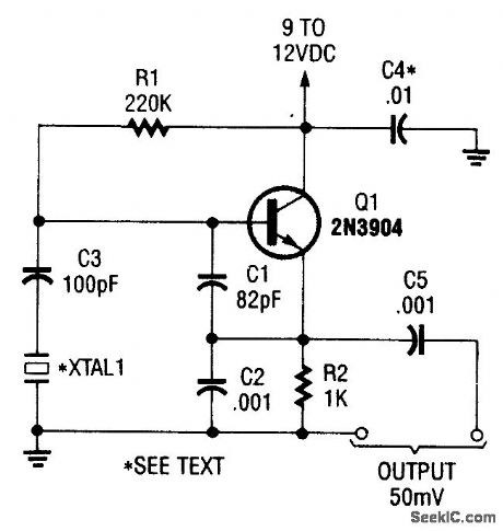
This is a simple Colpitts crystal oscillator for 1 to 20 MHz, can be easily made from junk-box parts(provided that a crystal is handy). (View)
View full Circuit Diagram | Comments | Reading(7539)
UNIJUNCTION_TRANSISTOR_OSCILLATOR
Published:2009/7/19 22:57:00 Author:Jessie
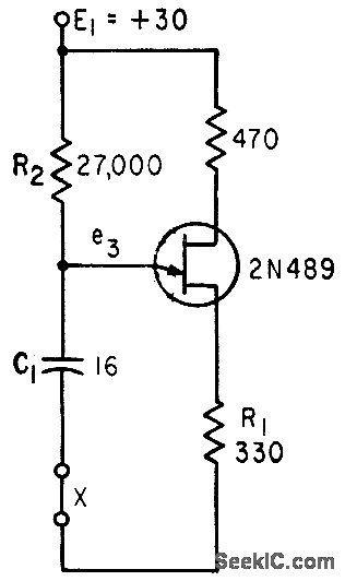
If circuit is broken at X, discharge current of C1 can be used to shut off transistor stage. -A. G. Lloyd, Overload Protection for Transistor Voltage Regulators, Electronics, 33:52, p 56-59. (View)
View full Circuit Diagram | Comments | Reading(867)
SOUND_EFFECTS_GENERATOR
Published:2009/7/10 2:19:00 Author:May
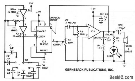
A variable clock-pulse generator is made up of two sections of IC1 (a 4069 CMOS hex inverter), R1, 51, and capacitors C1 through C6. By adjusting R1 and switching one of the capacitors into the circuit, the clock's pulse rate can be varied over a wide range.The TL507C converts analog signals-in this case the output of IC3, an LM386 audio amplifier-into digital signals. The conversion is accomplished using the single-slope method; it involves comparing an internally generated ramp signal to the analog input signal and a 200-mV reference voltage.The square-wave output from the a/d converter is fed to IC3 through a network consisting of R2, R3, and C7. Resistor R2 controls the amplitude of the pulses. Resistor R3 and capacitor C7 form a variable tone-control filter and a differentiator circuit that converts a square wave into a spiked waveform. That waveform is amplified by IC3, and the resulting output is fed back into the analog input of IC2, as well as to an 8-Ω speaker. By adjusting R1 and selecting one of the six capacitors with S1-thus varying the clock frequency-and by varying R2 and R3, you can produce many sounds. (View)
View full Circuit Diagram | Comments | Reading(0)
SIMPLE_THIRD_OVERTONE_OSCILLATOR
Published:2009/7/10 2:18:00 Author:May
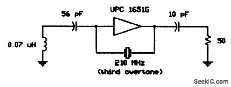
Using a 210-MHz third overtone crystal,this circuit operates directly at the crystal frequency,with210-MHz output and no multiplier stages. (View)
View full Circuit Diagram | Comments | Reading(664)
SIMPLE_FUNDAMENTAL_CRYSTAL_oscILLATOR
Published:2009/7/10 2:17:00 Author:May
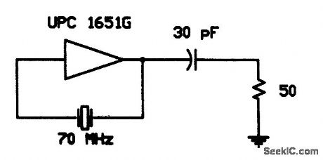
This simple fundamental oscillator uses a μPC1651G IC and two components. The crystal is funda-mental. (View)
View full Circuit Diagram | Comments | Reading(696)
SINGLE_CHIP_MELODY_GENERATOR
Published:2009/7/10 2:13:00 Author:May
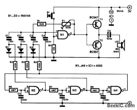
This melody generator, based on a 4093 CM0S Schmitt trigger, can be used in alarms, doorbells, and cars (audible reverse gear or lights-on indicator).Three of the four NAND gates in the 4093 are connected in series by RC networks. Oscillation is affected by feedback of the output signal of N4 to the input of N2. The logic-high levels produced by the cascaded gates in the oscillator circuit are used to bias one of associated diodes D1, D2, or D3). The relevant diode connects one of the frequency-determining capacitors (C1 through C3) to tone oscillator N1. The audio signal available when S1 is pressed is applied to complementary transistor pair (T1/T2) that drives the loudspeaker. The frequency of the emitted tone can be adjusted to individual taste with preset P1. (View)
View full Circuit Diagram | Comments | Reading(2520)
FIXED_GAIN_ANTENNAFIER
Published:2009/7/19 22:39:00 Author:Jessie
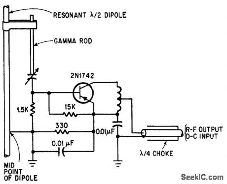
Transistorized dipole antennafier operates with fixed bias for maximum gain or minimum noise temperature. Gamma rod provides matching so transistor sees pure resistance.-J. F. Rippin, Making the Antenna an Active Partner, Electronics, 38:16, p 93-96. (View)
View full Circuit Diagram | Comments | Reading(778)
FOUR_TRANSISTOR_TRF
Published:2009/7/19 22:37:00 Author:Jessie
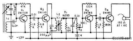
Single-channel receiver fits into one temple piece of eyeglass frame, with ferrite antenna in other piece, and separate miniature earphone.-H. F. Cooke, Transistor Eyeglass Radio, Electronics, 32:39, p 88. (View)
View full Circuit Diagram | Comments | Reading(912)
DOUBLECONVERSION_F_M_SUPERHETERO_DYNE
Published:2009/7/19 23:26:00 Author:Jessie
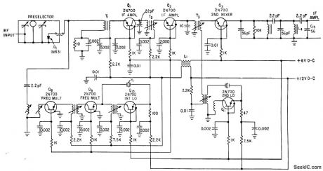
Common-base connections in local oscillators Q10 and Q11 give stability with minimum components in 20.channel Mercury spacecraft command receiver. Each frequency multiplier doubles frequency of first local oscillator. If output is 10.7 Mc.-R. Elliott, First Details on Mercury Spacecraft Command Receiver, Electronics, 36:5, p 32-35.
(View)
View full Circuit Diagram | Comments | Reading(1439)
| Pages:84/195 At 2081828384858687888990919293949596979899100Under 20 |
Circuit Categories
power supply circuit
Amplifier Circuit
Basic Circuit
LED and Light Circuit
Sensor Circuit
Signal Processing
Electrical Equipment Circuit
Control Circuit
Remote Control Circuit
A/D-D/A Converter Circuit
Audio Circuit
Measuring and Test Circuit
Communication Circuit
Computer-Related Circuit
555 Circuit
Automotive Circuit
Repairing Circuit