
Signal Processing
Index 98
Linear_voltage_controlled_oscillator
Published:2009/7/20 23:26:00 Author:Jessie
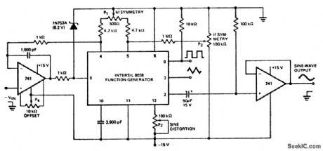
Linear voltage-controlled oscillator (courtesy Intersil, Inc.) (View)
View full Circuit Diagram | Comments | Reading(1582)
Frequency_modulated_52_MHz_oscillator
Published:2009/7/20 23:24:00 Author:Jessie
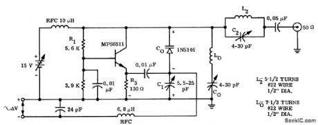
Frequency-modulated 52 MHz oscillator. The circuit uses an MPS6511 transistor especially designed for oscillators. The 1N5146 is a varactor diode rated at 33 pF for are verse bias of -4volts. L2 and L3 are used to tune out unwanted harmonics. Audio inputs should be limited to 200 mV or less (courtesy Motorola Semiconductor Products, Inc.). (View)
View full Circuit Diagram | Comments | Reading(813)
105_MHz_crystal_oscillator_operating_at_the_fifth_overtone
Published:2009/7/20 23:21:00 Author:Jessie
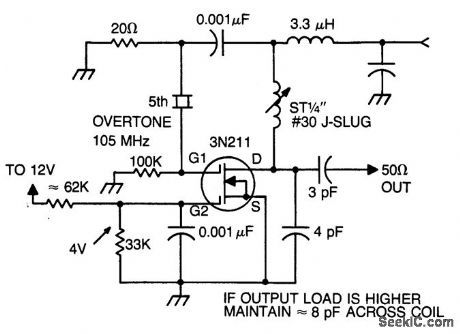
105 MHz crystal oscillator operating at the fifth overtone (courtesy Texas Instruments Incorporated). (View)
View full Circuit Diagram | Comments | Reading(883)
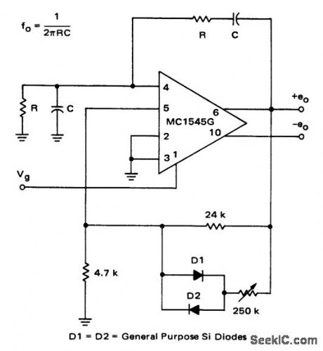
Gated_oscillator_using_an_MC1545G_video_amplifier_chip
Published:2009/7/20 23:19:00 Author:Jessie
Gated oscillator using an MC1545G video amplifier chip (courtesy Motorola Semiconductor Products Inc.). (View)
View full Circuit Diagram | Comments | Reading(567)
SINE_COSINE_OSCILLATOR
Published:2009/7/21 1:44:00 Author:Jessie
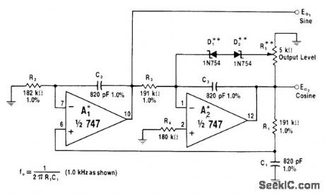
Two oscillators in cascade with positive feedback generate two sine waves in quadrature (differing in phase by 90°). Limiting network D1-D2-R5 is used around A2 to prevent oscillator from stabilizing at saturation limit of A2. R5 is used to set output at any level above zener limits of D1-D2. Frequency is 1 kHz for values shown.-W. G. Jung, IC Op-Amp Cookbook, Howard W. Sams, Indianapolis, IN, 1974, p 371-372. (View)
View full Circuit Diagram | Comments | Reading(1079)
BAND_EDGE_MARKER
Published:2009/7/21 1:41:00 Author:Jessie
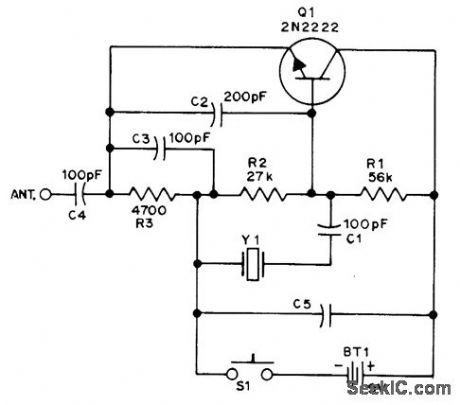
Series-tuned Colpitts crystal oscillator feeding 10-inch insulated-wire antenna provides sufficient signal radiation for pickup by nearby communication receiver. Used to provide band-edge marker for calibrating receiver tuning dial so receiver meets FCC rules for checking transmitter frequency when using VFO rather than crystal control for Novice transmitter in amateur bands. Crystal can be either for 40- or 80-meter band. Although band-edge frequency is convenient for warning when transmitter is going off frequency, calibration can be done with any frequency in or near band of interest. C5 is 0.25 μF.-K. Negoro, A Band-Edge Marker Generator, QST, April 1973, p 16-17. (View)
View full Circuit Diagram | Comments | Reading(1003)
LAB_GENERATOR_CALIBRATOR
Published:2009/7/21 1:39:00 Author:Jessie
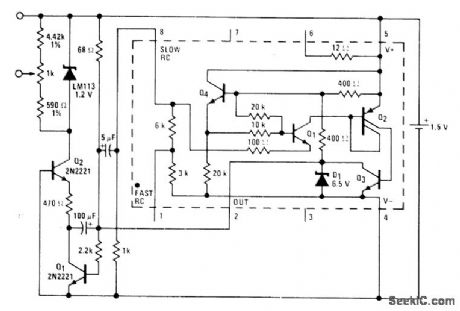
Portable design operating from single flashlight D cell uses National LM3909 flasher IC to produce clean rectangular wave that can be adjusted to exactly 1 V. Pulse width is 1.5 ms and OFF interval between pulses is 5.5 ms. Useful for calibrating oscilloscopes and adjusting their probes. Article describes operation of circuit in detail, Current drain is low enough to give 500 h of operation.-P. Lefferts, Power-Miser Flasher IC Has Many Novel Applications, EDN Magazine, March 20, 1976, p 59-66. (View)
View full Circuit Diagram | Comments | Reading(689)
UNIVERSAL_TEST_OSCILLATOR
Published:2009/7/21 1:38:00 Author:Jessie
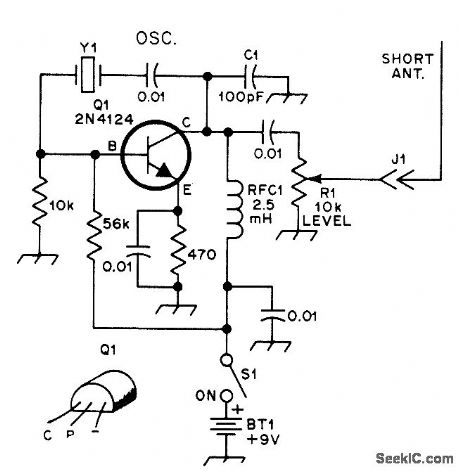
Crystal is in feedback path of Pierce oscillator, between base and collector of al, with 2.5-mH RF choke in place of tuned collector circuit. Oscillator works from 400 kHz to 20 MHz, depending on crystal. Designed for fundamental crystals; third overtone types will oscillate but at fun-damental. Value of 01 is for 1 MHz and higher; increase to 330 pF for lower frequencies. An-tenna can be 20-inch wire; increasing length increases signal radiation. Can be used as signal source for receiver alignment (with either radiated or probe-coupled signal), as marker generator, or in combination with station receiver as code-practice oscillator.-D. DeMaw, Build a UTO-1, QST, Oct. 1977, p 19-21. (View)
View full Circuit Diagram | Comments | Reading(2505)
455_kHz_FOR_IF_ALIGNMENT
Published:2009/7/21 1:37:00 Author:Jessie
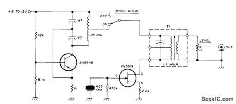
Simple crystal-controlled signal generator serves for aHgning IF strips. Amplitude modulator uses Colpitts 1-kHz oscillator circuit, with surplus 88-mH toroid in tank circuit; tie two adjacent leads together to provide center tap. T1 is 455-kHz IF transformer from AM transistor radio, used to tune drain circuit and obtain low output impedance. Current drain is about 7 mA with 12-V supply and 5 mA with 9-V battery.-C. Hall, 455-kHz 1-F Alignment Signal Generator, Ham Radio, Feb. 1974, p 50-52. (View)
View full Circuit Diagram | Comments | Reading(3495)
25_kHz_CALIBRATOR
Published:2009/7/21 1:36:00 Author:Jessie
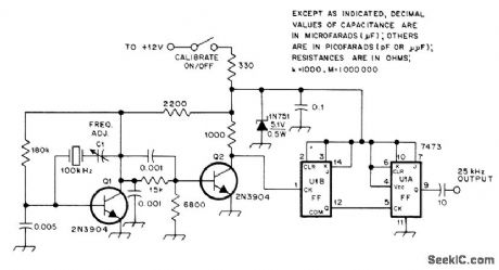
Addition of one 7473 dual JK flip-flop IC to circuit of Radio Shack 28-140 100-kHz calibrator kit provides conversion to 25 kHz for checking frequency settings of am-ateur receivers. Amplitude of output is 5 V P-P square wave with rich harmonic content. Originally designed for use with HW-8 Heathkit am ateur receiver. Output of calibrator is coupled to receive side of antenna relay through 10-pF capacitor. Article covers initial calibration.-D. Karpiej, A 25-kHz Calibrator for the HW-8, QST, Oct. 1978, p 20-21. (View)
View full Circuit Diagram | Comments | Reading(1838)
TRACKING_GENERATOR
Published:2009/7/21 1:34:00 Author:Jessie
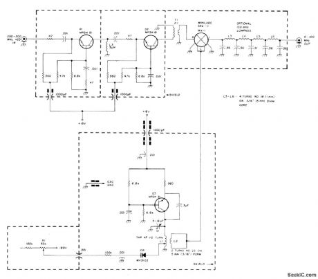
Used with spectrum analyzer to generate CW signal corresponding to frequency to which analyzer is tuned, for evaluation of filter response.Q1 and Q2 provide gain and isolation between 200-MHz oscillator, Q3 and first IF amplifier of analyzer. R1 provides fine tuning. MX1 mixes 200-MHz output with signal from 200-300 MHz first local oscillator to provide 100-kHz to 100-MHz tracking signal. Optional 130-MHz low-pass filter attenuates 400-500 MHz component generated by mixer in tracking generator-W, Ryder, Spectrum Analyzer Tracking Generator, Ham Radio, April 1978, p 30-32. (View)
View full Circuit Diagram | Comments | Reading(1510)
TRANSFORMER_COUPLED_COLLECTOR_MODU__LATED_TRANSMITTER
Published:2009/7/20 23:57:00 Author:Jessie
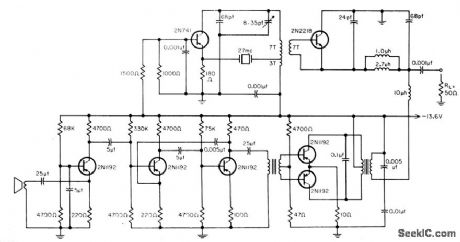
Widely used in a-m citizen's band (27-mc) transmitters. Modulation amplifier should be adjusted for dipping at 300-mw level, with passband from 300 to 3,000 cps. Input of 0.6 my will pro vide rated output of 780 mw at 70 db gain Large modulation transformer is required.- B. Rheinfelder, modulation Techniques for Transistorized A.M Transmitters, EEE, 11:7, p 54-57. (View)
View full Circuit Diagram | Comments | Reading(808)
PRECISION_45_MHz_FM_FOR_TV_IF
Published:2009/7/21 2:02:00 Author:Jessie


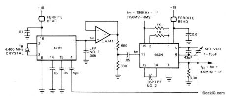
Translation loop made from Signetics 561N and 562N PLLs produces 4.5-MHz signal with deviation of ±25 kHz, using 4.400-MHz crystal to control reference frequency. Modulation frequency is 400Hz. - Signetics Analog Data Manual, Signetics.Sunnyvale ,CA,1977,p843-845. (View)
View full Circuit Diagram | Comments | Reading(668)
15_Hz_TO_40_kHz_IN_FOUR_RANGES
Published:2009/7/21 1:59:00 Author:Jessie
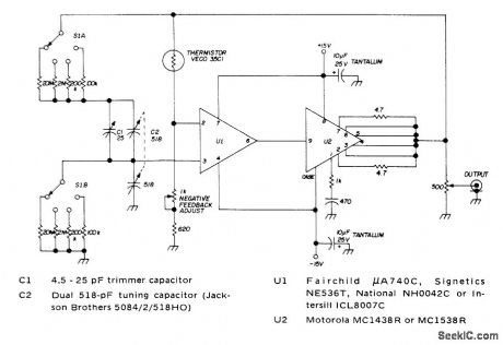
Tunable wide-range Wien-bridge audio oscillator is switched to cover 15-200 Hz, 150-2000 Hz, 1.5-20 kHz, and 3-40 kHz. U1 is high-input-impedance opamp in bridge circuit using thermistor as nonlinear feedback element. C1 is adjustable in series branch of bridge to compensate for capacitance (about 10pF) of ungrounded common terminal of dual tuning capacitor. Use ±15V dual regulated supply.-H. Olson, Integrated-Circuit Audio Oscillator, Ham Radio, Feb. 1973, p 50-54. (View)
View full Circuit Diagram | Comments | Reading(988)
100_kHz_CRYSTAL
Published:2009/7/21 1:56:00 Author:Jessie
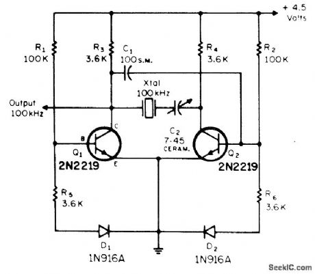
Drives JK or RS flip-flops to provide markers at 10-kHz or 20-kHz intervals for calibrating transmitter, receiver, or transceiver. D1 and D2, used to stabilize output, can be eliminated if desired; R5 and R6 are then grounded directly. Transistor and diode types are not critical.-G. F. Moynahan, An Improved Crystal Calibrator Using Solid-State Techniques, CQ, May 1972, p 18 and 20. (View)
View full Circuit Diagram | Comments | Reading(1464)
FREQUENCY_STANDARD
Published:2009/7/21 1:54:00 Author:Jessie
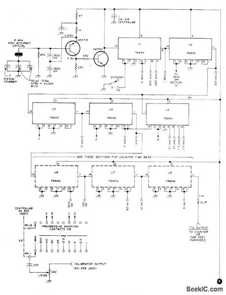
Uses high-performance TTL ICs operating from regulated 5-V supply furnishing 260 mA, connected to point X. Provides choice of 18 precision frequencies if all ICs are used, or 8 marker frequencies if only upper three ICs are used. Adjustable level control permits matching output of frequency calibrator to incoming signals such as from WWV, or turning full on for strong, clear markers.HEP715 oscillator transistor is coupled to TTL by HEP50 transistor. 7493 binary dividers U1 and U5 divide by factor of 2, with 7490 decade dividers making up remainder of logic. Reset pins 2 and 3 control operation of logic, either with S1 or with progressively shorted contacts of rotary switch S2. Crystal should be ordered for 0.0005% tolerance, F-700 or SP7.P holder, 32-pF load, and 4 MHz at room temperature.-B. Kelley, Universal Frequency Standard, Ham Radio, Feb. 1974, p 40-47. (View)
View full Circuit Diagram | Comments | Reading(914)
1_watt_noninverting_power_amplifier_for_split_power_supply_operation_using_an_MC1554
Published:2009/7/21 1:52:00 Author:Jessie
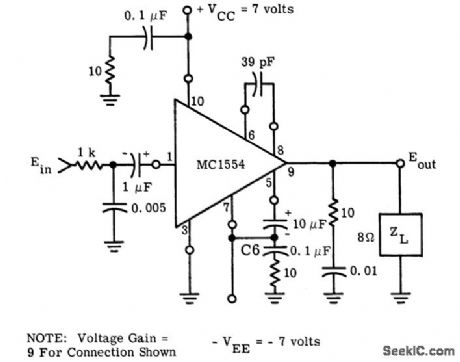
1-watt noninverting power amplifier for split power supply operation using an MC1554. As shown voltage gain is nine (courtesy Motorola Semiconductor Products Inc.). (View)
View full Circuit Diagram | Comments | Reading(621)
30_kHz_MARKERS_FOR_2_METER_FM
Published:2009/7/21 1:47:00 Author:Jessie
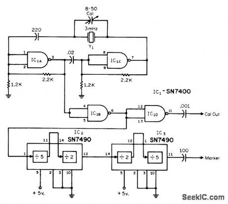
Crystal is placed in loop of standard TTL MVBR, Circuit is modified so 32-pF parallel-mode unit will work into effective load of 32 pF. Series 220-pF capacitor raises crystal frequency enough to permit accurate frequency adjustment by trimmer. Oscillator output is fed to two decade dividers; output of second decade IC3 is 30-kHz square wave with 20% duty factor, coinciding with standard 2-meter FM channels. Regulated sup-ply is 5 VDC at 110 mA.-G. E. Zook, Channel Marker Generator, CQ, April 1972, p 41-42. (View)
View full Circuit Diagram | Comments | Reading(733)
WAVEFORM_SYNTHESIZER
Published:2009/7/21 1:45:00 Author:Jessie
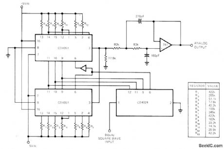
Values of weighting resistors connected to inputs of multiplexer chips determine waveform of analog output. CD4024 binary counter sequences multiplexers through all states at 16 times fundamental frequency of desired waveform. Active filter using 741 opamp removes components of sampling frequency. For near-approximation to sine wave, weighting resistors range from about 15Kto 425K.-J. R. Tracy, CMOS Circuits Generate Arbitrary Periodic Waveforms, EDN Magazine, Aug. 20, 1973, p 86-87. (View)
View full Circuit Diagram | Comments | Reading(1389)
32_kHz_DMOS_OSCILLATOR
Published:2009/7/21 2:31:00 Author:Jessie
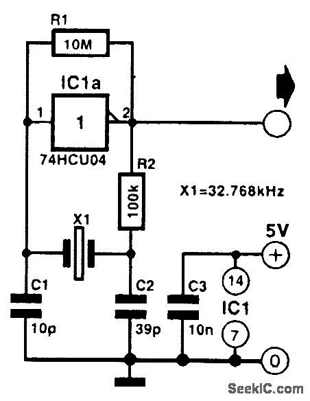
Capacitors C1 and C2 and the crystal form a π section that causes a phase shift of 180°. Circuit IC1 is an inverter, which also causes a phase shift of 180°. Thus the total phase shift is 360°, which is necessary if the oscillations are to be sustained. (View)
View full Circuit Diagram | Comments | Reading(707)
| Pages:98/195 At 2081828384858687888990919293949596979899100Under 20 |
Circuit Categories
power supply circuit
Amplifier Circuit
Basic Circuit
LED and Light Circuit
Sensor Circuit
Signal Processing
Electrical Equipment Circuit
Control Circuit
Remote Control Circuit
A/D-D/A Converter Circuit
Audio Circuit
Measuring and Test Circuit
Communication Circuit
Computer-Related Circuit
555 Circuit
Automotive Circuit
Repairing Circuit