
Signal Processing
Index 99
OPERATIONAL_TRANSCONDUCTANCE_AMPLIFIER_OSCILLATOR
Published:2009/7/21 2:30:00 Author:Jessie
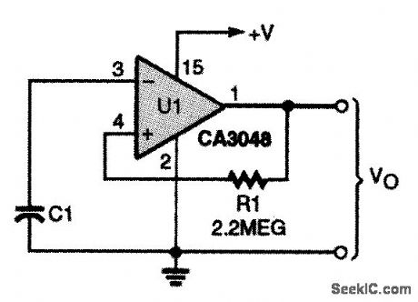
The only components in the simple circuit shown are a CA3048 OTA, a feedback resistor (R1), and a timing capacitor (C1). The output frequency is approximately given by:
ƒo≈1/(2πR1C1)
Timing resistor R1 should be from 1 to 3.9 MΩ .When R1 is of a greater value, the circuit some-Fig, 75-5 times stops oscillating, depending on the specific CA3048 used. (View)
View full Circuit Diagram | Comments | Reading(1187)
NE602_LOCAL_OSCILLATOR_CIRCUITS
Published:2009/7/21 2:27:00 Author:Jessie


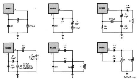
The local oscillator for the NE602 can take the form of either a crystal-controlled (a through d) or a resonant-tank circuit(e and ƒ). (View)
View full Circuit Diagram | Comments | Reading(3878)
SPARK_GAP_OSCILLATOR
Published:2009/7/21 2:25:00 Author:Jessie
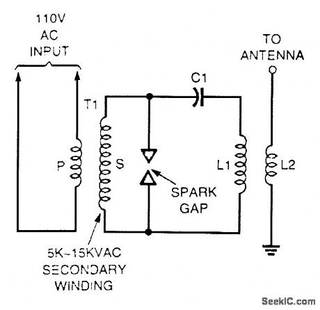
A high-voltage current-limiting transformer (T1) supplies power to the basic LC tuned circuit. As C1 charges to near the transformer's maximum output voltage, the spark gap's air space breaks down, completing the circuit between the inductor and capacitor, L1 and C1. The tremendous inductive kick in the circuit is caused by the inductive field collapse when the spark gap shorts out the LC series circuit. The LC tuned circuit oscillates in a very broadband manner. (View)
View full Circuit Diagram | Comments | Reading(1960)
MMIC_AMPLIFIER_OSCILLATOR
Published:2009/7/21 2:24:00 Author:Jessie
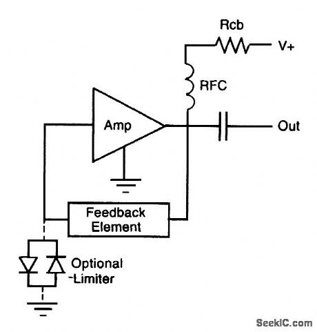
The figure shows a basic oscillator circuit using an MMIC amplifier. (View)
View full Circuit Diagram | Comments | Reading(707)
HIGH_STABILITY_OSCILLATORS
Published:2009/7/21 2:39:00 Author:Jessie


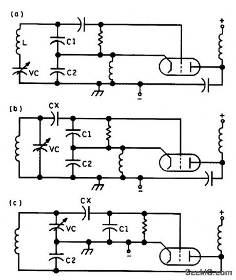
These three high-stability oscillator circuits show the minor, but significant, differences between them: (a) Gouriet-Clapp oscillator with series resonance; (b) Seller low-C Colpitts oscillator with parallel resonance; (c) the Vackar oscillator, in which the ratios C2.Vc and C1:Cx should both be about 1:6. (View)
View full Circuit Diagram | Comments | Reading(914)
1296_MHz
Published:2009/7/21 2:38:00 Author:Jessie
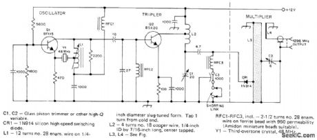
Can be used as signal source for receiver adjustment and antenna testing, or as minibeacon on 1296 MHz. 48-MHz oscillator and clipper feed 144 MHz to 1N914 diode which multiplies frequency by 9. Half-wavelength strip line tank L3-C2 rejects other harmonics. Shorting link below RFC3 is removed for measuring code Current.-A 1296-MHz Signal Source, QST, March 1977, p 26. (View)
View full Circuit Diagram | Comments | Reading(2674)
ACCURATE_RING_OSCILLATOR
Published:2009/7/21 2:37:00 Author:Jessie
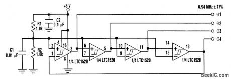


Four square-wave outputs can be produced with a single IC using this simple circuit setup. It takes advantage of the tightly controlled propagation delay of the LTC1520 quad line receiver to pro-duce a stable set of output waveforms. The circuit as shown uses all four comparator stages to de-liver quadrature output waveforms (90° phase increments). Because tPLH/tPLH skew (the difference between low-to-high and high-to-low propagation delays) is typically only 500 ps, the waveforms have duty factors that are very close to 50 percent. Channel-to-channel skew is usually only 400 ps, holding phase error between outputs to around 5°. An eight-phase oscillator (with 45° phase incre-ments) can be constructed by inverting φ 1 to φ (4 through another four LTC1520 comparators. It is also possible to build two-phase and three-phase ring oscillators by using two- and three-comparator sections, respectively. Just be sure that an odd number of inversions are around the loop, otherwise, the oscillator becomes a latch! Each LTC1520 input has a Thevenin input resistance of ±18 kΩ to 2/3 Vcc For a more accurate 50-percent duty factor, the dc threshold should be biased closer to 1/2 Vcc. This is easily done by connecting an external resistor divider to pull the switching threshold near 1/2 Vcc as is done with R1 and R2 in this figure. The measured temperature stability of the depicted oscillator is very good, normally varying less than 5 percent from 0° to 70℃ . (View)
View full Circuit Diagram | Comments | Reading(905)
Push_pull_monolithic_Darlington_amplifier
Published:2009/7/21 2:36:00 Author:Jessie
Push-pull monolithic Darlington amplifier (courtesy Motorola Semiconductor Products Inc.). (View)
View full Circuit Diagram | Comments | Reading(1310)
FM_SIGNAL_GENERATOR_OR_WOBBULATOR
Published:2009/7/21 2:36:00 Author:Jessie
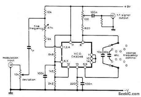
With sine-wave input, RCA CA3046 transistor array connected as VCO can be used as low-distortion FM signal generator. With sawtooth input, same arrangement serves as wobbulator. Increasing size of timing capacitor reduces op-erating frequency, permitting use down to audio frequencies as voltage-controlled oscillator in electronic organ.-J. L. Linsley Hood, Linear Voltage Controlled Oscillator, Wireless World, Nov, 1973, p 567-569. (View)
View full Circuit Diagram | Comments | Reading(2543)
ALIGNMENT_OSCILLATOR
Published:2009/7/21 2:35:00 Author:Jessie
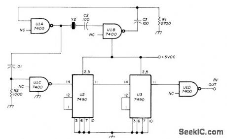
With 500-kHz crystal, output can be used as 5-kHz markers in sweep alignment procedure If SN7490P decade dividers are omitted and 455-kHz crystal is chosen, TTL circuit can be used to supply low IF value used by some receivers Circuit will oscillate up to several megahertz-J Carr, VHF FM Receiver Alignment Techniques, Ham Radio, Aug 1975,p14-22. (View)
View full Circuit Diagram | Comments | Reading(812)
GATE_DIP_OSCILLATOR
Published:2009/7/21 2:35:00 Author:Jessie
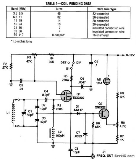
This dip oscillator, based on the classic vacuum-tube circuit, is very useful for checking tuned circuits and antennas, and is a valuable tool for the RF experimenter. Coil forms are 1/2-in diameter plastic tubing. (View)
View full Circuit Diagram | Comments | Reading(967)
NE602_AM_MODULATED_OSCILLATOR_CIRCUIT
Published:2009/7/21 2:32:00 Author:Jessie
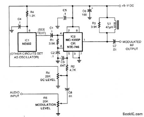
By using an MC-1350P modulator IC, the output of the NE602 can easily be amplitude -modulated. (View)
View full Circuit Diagram | Comments | Reading(2329)
Fixed_divide_by_ten_prescaler_using_an_MC1034,_MC1032,_MC1013_andMC1018
Published:2009/7/21 3:08:00 Author:Jessie
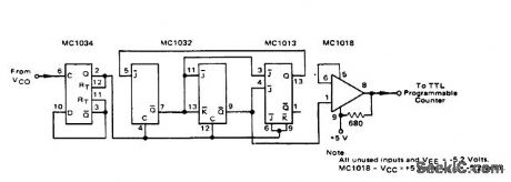
Fixed divide-by-ten prescaler using an MC1034, MC1032, MC1013 and MC1018(courtesy Motorola Semiconductor Products inc.). (View)
View full Circuit Diagram | Comments | Reading(667)
SQUARE_WAVE_GENERATOR
Published:2009/7/21 3:06:00 Author:Jessie
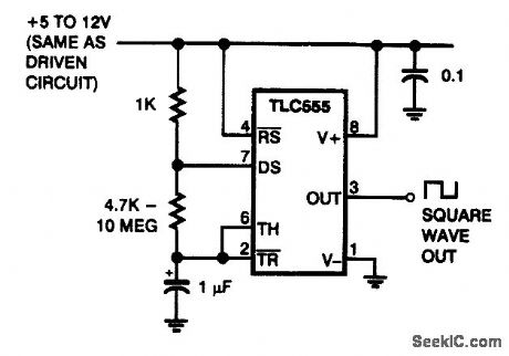
A square wave for driving a stepper motor driver can be obtained from this circuit, which uses a CMOS timer in an oscillator circuit. A potentiometer can be used to obtain variable-frequency output. (View)
View full Circuit Diagram | Comments | Reading(0)
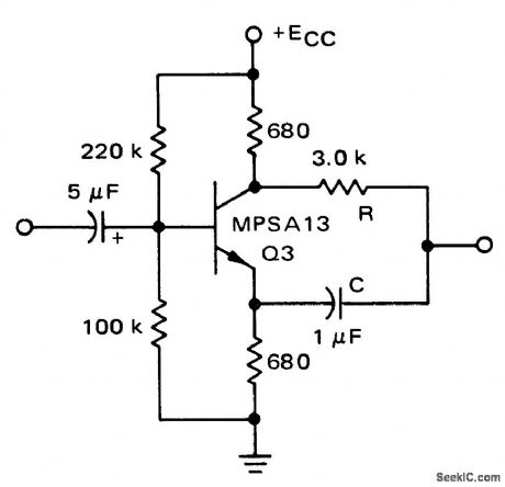
NEUTRALIZED_EMITTER_BOOSTS_H_F_GAIN
Published:2009/7/21 7:05:00 Author:Jessie
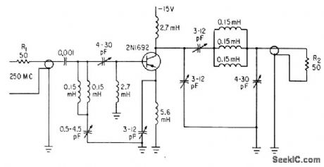
New operating mode increases h-f gain more thon 20 db, reduces interstage matching problems, improves selectivity and stability, and cuts cost. Based on neutralizing of emitter-circuit inductances with small variable capacitor from emitter to ground and r-f choke to provide d-c path from emitter to ground. Technique works best above 100 Mc.-Extend Transistor Frequency, Electronics, 34:44, p 25. (View)
View full Circuit Diagram | Comments | Reading(803)
1_W_AT_170_MC
Published:2009/7/21 7:04:00 Author:Jessie
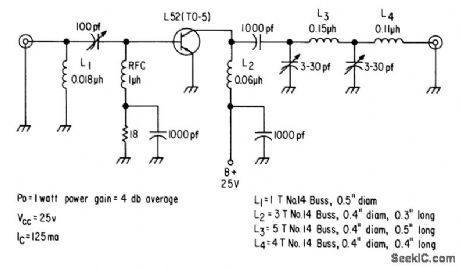
Single L52 feeds 1 w to 50-ohm antenna through pi-L network. Power gain is 4 db and efficiency is 30% for class C operation.-Texas Instruments Inc., Solid.State Communications, McGraw-Hill, N.Y., 1966, p 323. (View)
View full Circuit Diagram | Comments | Reading(572)
175_MC_F_M_MOBILE_AMPLIFIER
Published:2009/7/21 7:03:00 Author:Jessie
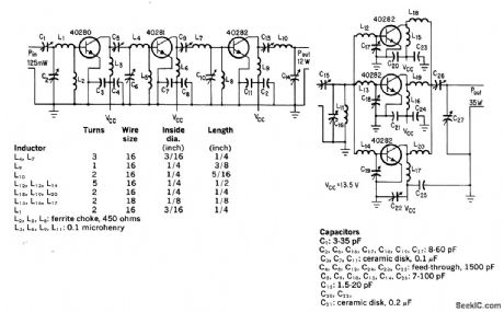
Overlay transistors operating directly from 13.5-v auto battery give 12 w from three stages and 35 w when output stage is added. Overall d-c to r-f efficiency of transmitter is about 60%.-D. J. Donahue and B. A. Jacoby, Putting the Overlay to Work at High Frequencies, Electronics, 38:17, p 78-81. (View)
View full Circuit Diagram | Comments | Reading(741)
100__140__180_watt_linear_amplifier_for_16_to_30_MHz_136_volt_mobile_operation_
Published:2009/7/21 6:09:00 Author:Jessie
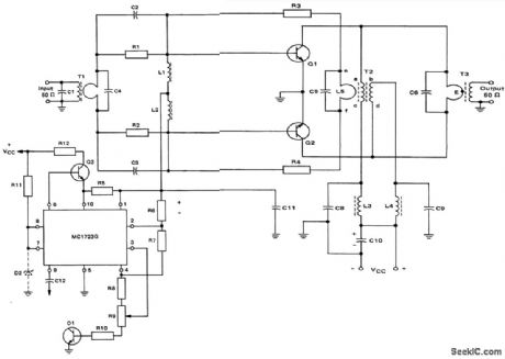
100-/140-/180-watt linear amplifier for 1.6 to 30 MHz 13.6-volt mobile operation (courtesy Motorola Semiconductor Products Inc.). (View)
View full Circuit Diagram | Comments | Reading(679)
6O0_kHz_TO_12_MHz
Published:2009/7/21 3:23:00 Author:Jessie
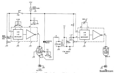
Uses Motorola MC4024P or HEP3805P dual voltage-controlled MVBR or VCO. 0ne half is used to produce rectangular RF output and other half to generate rectangular 1-kHz modulation frequency. RF output frequency is proportional to 11C, with 365-pF variable capacitor providing tuning over 20:1 range from 600 kHz to 12 MHz. Use large dial for calibration. Half of MC3029P line-driver NAND gate follows each of MVBRs in MC4024P to provide isolation and to drive 50-Ohm lines with either output. Output voltage is well over 1 V P-P. T1 is 88-mH toroid with 30 turns No. 26 enamel wound over it as secondary. Use regulated supply.-H. Olson, Wide Range RF Signal Generator, Ham Radio, Dec. 1973, p 18-21. (View)
View full Circuit Diagram | Comments | Reading(1040)
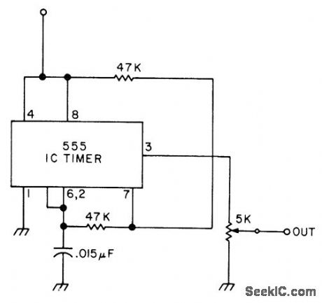
1_kHz_SQUARE_WAVE
Published:2009/7/21 3:20:00 Author:Jessie

Useful for signal-tracing from audio frequencies to several mega-hertz because 1000-Hz square-wave output of 555 timer is rich in harmonics. Use 5-V supply.Developed for checking audio, IF, and BF stages of amateur receiver operating on 160- to 40-m bands.-J. J. Carr, How to Become a Trouble-shooting Wizard, 73 Magazine, Jan, 1976, p 138-143. (View)
View full Circuit Diagram | Comments | Reading(715)
| Pages:99/195 At 2081828384858687888990919293949596979899100Under 20 |
Circuit Categories
power supply circuit
Amplifier Circuit
Basic Circuit
LED and Light Circuit
Sensor Circuit
Signal Processing
Electrical Equipment Circuit
Control Circuit
Remote Control Circuit
A/D-D/A Converter Circuit
Audio Circuit
Measuring and Test Circuit
Communication Circuit
Computer-Related Circuit
555 Circuit
Automotive Circuit
Repairing Circuit