
Signal Processing
Index 85
NR_DIODE_AS_R_F_OSCILLATOR
Published:2009/7/19 23:25:00 Author:Jessie
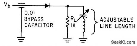
Simple negative-resistance diode circuit can develop several milliwatts at frequencies up to 300 Mc.-A. P. Schmid, Jr., Negative-Resistance Diode Handles High Power, Electronics, 34:34, p 44-46. (View)
View full Circuit Diagram | Comments | Reading(690)
CB_CRYSTAL_OSCILLATOR
Published:2009/7/19 23:24:00 Author:Jessie
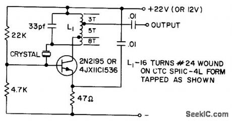
Uses low-cost crystal having high series resistance, up to 30 ohms. Provides adequate output to supply most master oscillator-power amplifier applications. Output tap is arranged to match directly a companion 2N2195 grounded-base amplifier. Crystal is 3rd overtone type.- Transistor Manual, Seventh Edition, General Electric Co., 1964, p 211. (View)
View full Circuit Diagram | Comments | Reading(962)
MILLIMETER_WAVE_DETECTOR
Published:2009/7/19 23:24:00 Author:Jessie
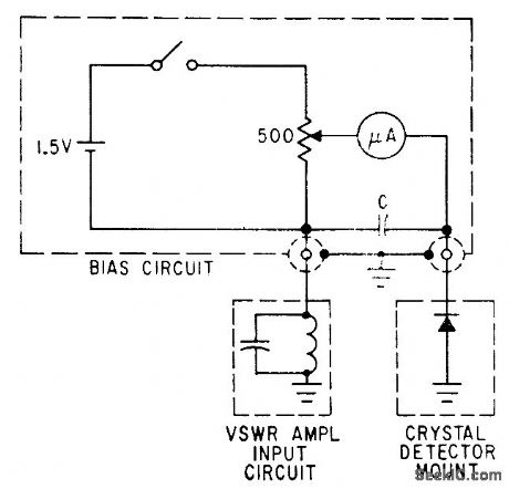
Biasing with 1N53 crystal detector increases gain 20 db at 73 Mc.-K. Ishii and A. L. Brault, Crystal Biasing Improves Millimeter-Wave Detector, Electronics, 34:24, p 65. (View)
View full Circuit Diagram | Comments | Reading(817)
_TWO_TRANSISTOR_REFLEX_RADIO
Published:2009/7/19 23:23:00 Author:Jessie
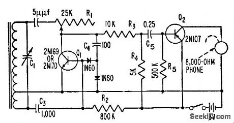
Q1 is used regeneratively as r-f amplifier and reflexively as first a-f amplifier, while Q2 serves as power amplifier.-S. A. Sullivan, Transistor Radio Uses Few Parts, Electronics, 31:1, p 90-92. (View)
View full Circuit Diagram | Comments | Reading(1611)
SATURABLE_REACTOR_OSCILLATOR
Published:2009/7/19 23:21:00 Author:Jessie
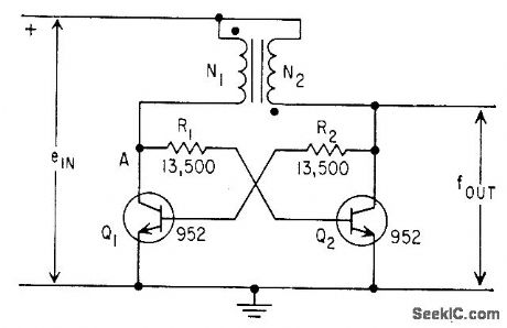
Timebase integration of a variable is performed by counting cycles of saturable-reactor oscillator whose frequency is proportional to the variable. linearity is within 1% of full scale.-L. W. Langley, Saturable-Core Oscillator Integrates Gas-Flow Data, Electronics, 32:4, p 42-43. (View)
View full Circuit Diagram | Comments | Reading(1207)
SUPER_SOUND_GENERATOR
Published:2009/7/10 1:47:00 Author:May
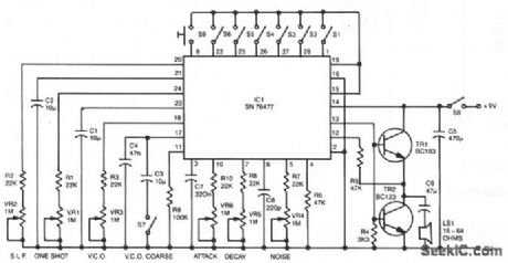
Six preset controls and seven selector switches enable a vast range of different sounds to be produced and altered at will. Such sounds as steam trains chuffing, helicopters flying, bird chirping, and machine guns firing are possible, as well as the usual police sirens, phaser suns, and bomb explosions. The circuit incorporates an amplifier giving 150-mW output into a small loudspeaker. Alternatively, a separate amplifier system can be used for disco effects, car alarms, etc. Continuous or one-shot sounds are possible. For one-shot sounds, a push-button switch is prodded, which can also be used to turn continuous sounds on and off. A single IC, SN76477, provides all of the sound generation circuits. (View)
View full Circuit Diagram | Comments | Reading(1974)
FREQUENCY_SYNTHESIZER
Published:2009/7/20 0:56:00 Author:Jessie
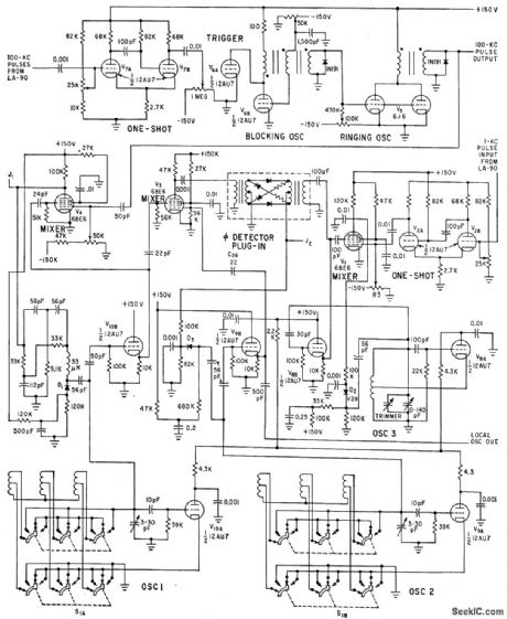
Three oscillators oscillator in synthesizer provide frequency increments of 1 kc from 2 to 30 mc, to replace local oscillator operation in double-conversion ssb receiver.-J. E. MacDowell, Stable Frequency Synthesizer Replaces Sideband Converter, Electronics, 35:25, p 41-43. (View)
View full Circuit Diagram | Comments | Reading(1093)
SIX_TRANSISTOR_9_V_BROADCAST
Published:2009/7/20 0:55:00 Author:Jessie
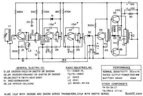
Nominal sensitivity is 20 microvolts per meter, rated power output 500 mw, and battery drain 10 ma.- Transistor Manual, Seventh Edition, General Electric Co., 1964, p 295. (View)
View full Circuit Diagram | Comments | Reading(912)
175_MC_R_F_STAGE
Published:2009/7/20 0:23:00 Author:Jessie
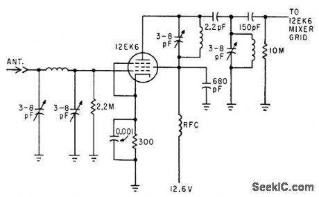
Pi network in grid circuit couples energy from antenna. Double-tuned capacitance-coupled transformer is used in plate circuit.-C. Gonzalez and R. J. Nelson, Design of Mobile Receivers with Low-Plate-Potential Tubes, Electronics, 33:34, p 62-65. (View)
View full Circuit Diagram | Comments | Reading(705)
HIGH_FREQUENCY_MOBILE_OSCILLATOR
Published:2009/7/20 0:20:00 Author:Jessie
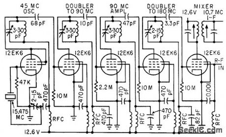
Uses third-overtone crystal oscillator with two doubler stages. To get adequate drive for doubler to 180 Mc, stage of straight-through amplification at 90 Mc is used.-C. Gonzalez and R. J. Nelson, Design of Mobile Receivers with Low-Plate-Potential Tubes, Electronics, 33:34, p 62-65. (View)
View full Circuit Diagram | Comments | Reading(692)
COLPITTS_CRYSTAL
Published:2009/7/20 0:18:00 Author:Jessie
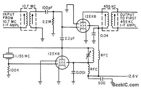
Oscillator uses 11.155-Mc tuned plate circuit for operation at crystal fundamental frequency. Other 12EK6 has no cathode bias and provides conversion gain of 10.-C. Gonzalez and R. J. Nelson, Design of Mobile Receivers with Low-Plate-Potential Tubes, Electronics, 33:34, p 62-65. (View)
View full Circuit Diagram | Comments | Reading(710)
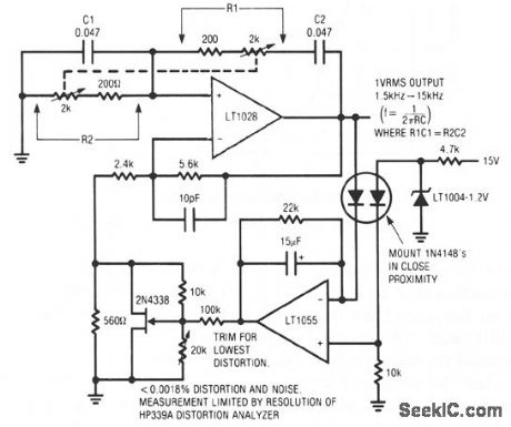
SUPER_LOW_DISTORTION_VARIABLE_SINE_WAVE_OSCILLATOR
Published:2009/7/10 1:35:00 Author:May
View full Circuit Diagram | Comments | Reading(847)
SINGLE_SUPPLY_WIEN_BRIDGE_OSCILLATOR
Published:2009/7/10 1:33:00 Author:May
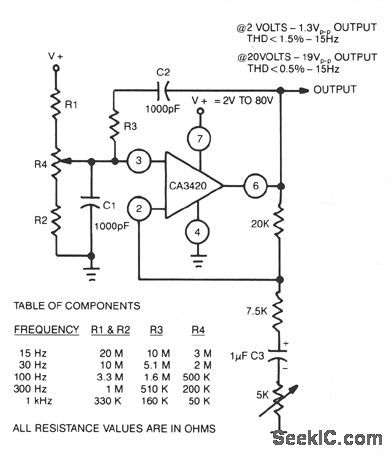
The adjustment of R4 contributes to the comparatively symmetrical output transfer characteristic of the CA3420 BiMOS op amp. To extend the lower operating frequency, remove C3 and use a dual supply. (View)
View full Circuit Diagram | Comments | Reading(1031)
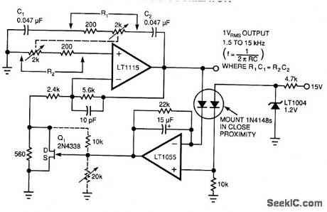
LOW_DISTORTION_THERMALLY_STABILIZED_WIEN_BRIDGE_OSCILLATOR
Published:2009/7/10 1:32:00 Author:May
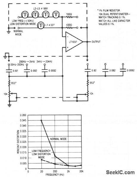
A variable Wien bridge provides frequency tuning from 20 Hz to 20 kHz. Gain control comes from the positive temperature coefficient of the lamp. When power is applied, the lamp is at a low resistance value, the gain is high, and oscillation amplitude builds. The lamp's gain-regulating behavior is flat within 0.25 dB over the 20 Hz-20 kHz range of the circuit. Distortion is below 0.003%. At low frequencies, the thermal time constant of the small normal-mode lamp begins to introduce distortion levels about 0.01%. This is because of hunting when the oscillator's frequency approaches the lamp's thermal time constant. This effect can be eliminated, at the expense of reduced output amplitude and longer amplitude settling time, by switching to the low-frequency, low-distortion mode. The four large lamps give a longer thermal time constant, and distortion is reduced. (View)
View full Circuit Diagram | Comments | Reading(844)
SINE_AND_SQUARE_WAVE_TTL_OSCILLATOR
Published:2009/7/10 1:32:00 Author:May
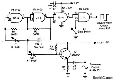
Using a Quad NAND Gate, the TTL oscillator can use fundamental crystals between 1 and 10 MHz. The sine-wave output is taken directly from the crystal, which acts as its ovrn filter, and yields a fairly clean sine wave. Adjust C1 and C2 for the best sine wave and also to set the crystal frequency. TTL square wave can be taken from U1D. The gate switch can be replaced with a Iogic gate to electronically control the output. (View)
View full Circuit Diagram | Comments | Reading(7035)
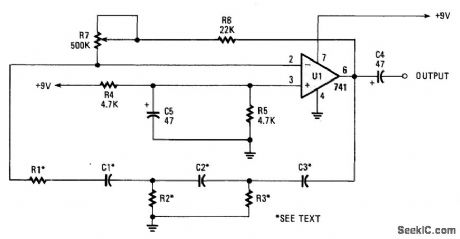
LOW_FREQUENCY_SINE_WAVE_GENERATOR
Published:2009/7/10 1:30:00 Author:May
Using a Wien-bridge oscillator, this circuit generates switch-selected frequencies from 1 to 20 Hz. A 741 op amp is used as the active element. (View)
View full Circuit Diagram | Comments | Reading(1915)
WIEN_BRIDGE_OSCILLATOR_1
Published:2009/7/10 1:29:00 Author:May
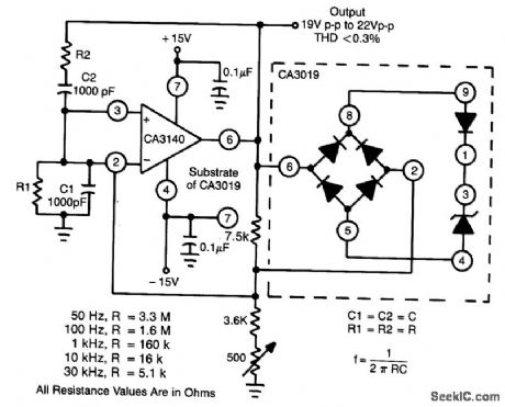
This circuit makes excellent use of high input impedance, high slew rate, ties of CA3140 BiMOS op amp, in combination with CA3019 diode array. (View)
View full Circuit Diagram | Comments | Reading(0)
WIEN_BRIDGE_OSCILLATOR
Published:2009/7/10 1:28:00 Author:May
This complex oscillator circuit uses a photocell and common-mode-suppression circuitry to achievedistortion of 0.0003%。 (View)
View full Circuit Diagram | Comments | Reading(0)
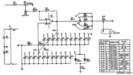
THREE_DECADE_15_Hz_TO_15_kHz_WIEN_BRIDGE_OSCILLATOR
Published:2009/7/10 1:26:00 Author:May
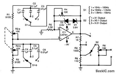
In this circuit, an LM741 op amp drives a Wien-bridge network using two zener diodes as an ampli-tude limiter. Range selection is done 'oy switch selecting the capacitors (C1 through C6) and tuning is done via a ganged pot. The output is about 8 Vpp max., depending on the setting of S2 and R6. R4 is set for maximum distortion consistent with stable output. (View)
View full Circuit Diagram | Comments | Reading(1789)
LOW_FREQUENCY_LO_OSCILLATOR
Published:2009/7/10 1:25:00 Author:May
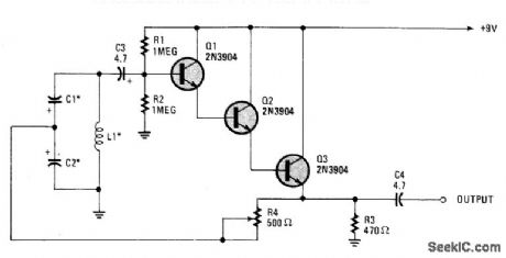
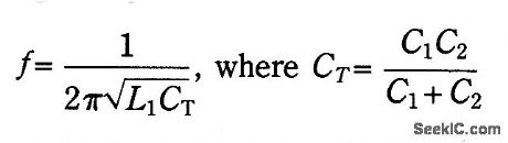
Basically a Hartley oscillator using a triple-emitter follower, this oscillator can be used at audio and low radio frequencies. The frequency is given by:At 1 kHz, typically C would be 4.7 μF tantalums, but this is only a guide as to convenient values to use. (View)
View full Circuit Diagram | Comments | Reading(991)
| Pages:85/195 At 2081828384858687888990919293949596979899100Under 20 |
Circuit Categories
power supply circuit
Amplifier Circuit
Basic Circuit
LED and Light Circuit
Sensor Circuit
Signal Processing
Electrical Equipment Circuit
Control Circuit
Remote Control Circuit
A/D-D/A Converter Circuit
Audio Circuit
Measuring and Test Circuit
Communication Circuit
Computer-Related Circuit
555 Circuit
Automotive Circuit
Repairing Circuit