
Signal Processing
Index 89
AM_radio_receiver_with_a_maximum_sensitivity_of_362_dB_m_at_1000_kHz
Published:2009/7/20 3:22:00 Author:Jessie
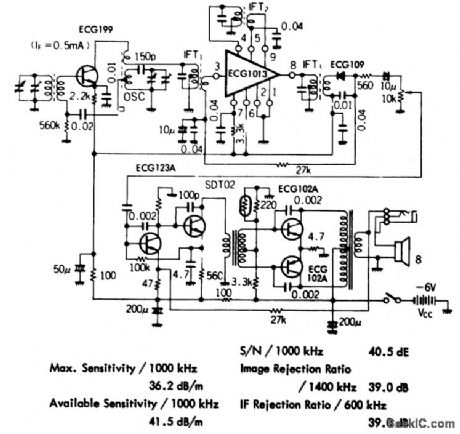
AM radio receiver with a maximum sensitivity of 36.2 dB/m at 1000 kHz.Available sensitivity is 41.5 dB/m at 1000 kHz.Sign alto noise ratio is 40.5 dB.Image rejection ratio is 39.0 dB at 1400 kHz.IF rejection ratio at 600 kHz is 39 dB.IF transformers and audio transformers are standard and can be purchased at Radio Shack,The same is true for the tuning capacitor(courtesy GTE Sylvania Incorporated). (View)
View full Circuit Diagram | Comments | Reading(809)
FM_stereo_demodulator_with_stereo_monaural_switch_and_audio_muting
Published:2009/7/20 3:18:00 Author:Jessie
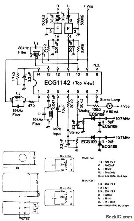
FM stereo demodulator with stereo-monaural switch and audio muting. Recommended supply voltage is 9 volts. Standby current is 10 mA. Input impedance is 20K. Audio muting is on at 0.85 volt and off at 1.08 volts. Stereo indicator is on at input voltage of 12 mV RMS and off at input voltage of 8.4mV RMS. Stereo-monaural switching occurs at 1.13 volts for stereo and 0.82 volt for monaural. Component F is a 38 kHz band eliminate filter (courtesy GTE Sylvania Incorporated). (View)
View full Circuit Diagram | Comments | Reading(680)
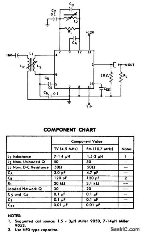
FM_detector_and_limiter_stage_for_45_MHz_or_107_MHz
Published:2009/7/20 3:17:00 Author:Jessie
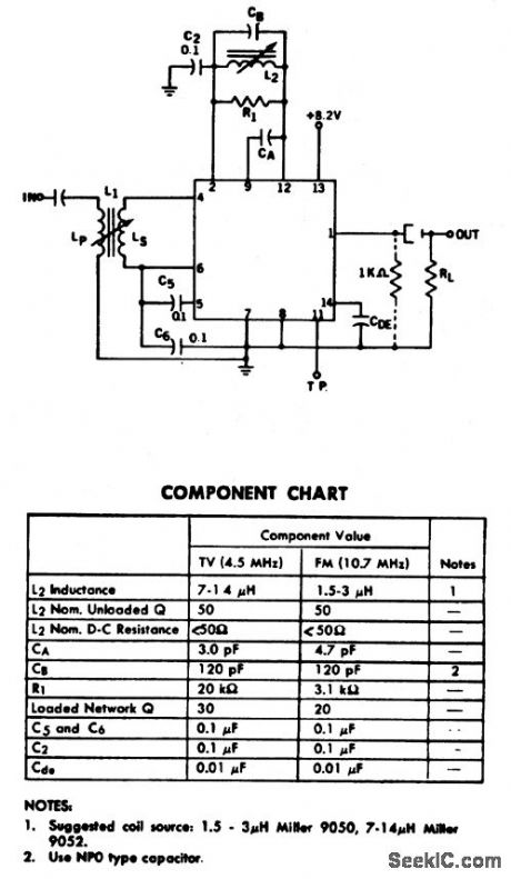
FM detector and limiter stage for 4.5 MHz or 10.7 MHz.using one ECG709. See component chart for appropriate frequency. Designed for use with an 8-volt supply, the ECG709 is a three-stage limiter with a balanced product detector. There are 19 transistors, 6 diodes, and 18 resistors inside the chip. Only one screw driver adjustment is necessary to tune the circuit (courtesy of GTE Sylvania Incorporated). (View)
View full Circuit Diagram | Comments | Reading(792)
The warping machine auto control energy-saver
Published:2011/7/22 20:38:00 Author:qqtang | Keyword: warping machine, auto control, energy-saver
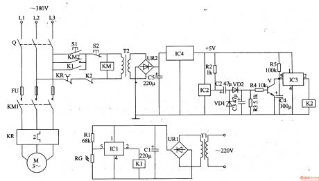
The working principle of the circuitThe warping machine auto control energy-saver consists of the light control circuit, magnetic control circuit, +5V power supply circuit and motor main control circuit, see as figure 8-134.
The light control circuit consists of the resistor RG, resistor R1, electric switch integrated circuit IC1, relay K1, filtering capacitor CI, rectifier bridge pile UR1 and power supply transformer T1. (View)
View full Circuit Diagram | Comments | Reading(1584)
FM_detector_stage_using_one_ECG708_IC
Published:2009/7/20 3:06:00 Author:Jessie
FM detector stage using one ECG708 IC. The output can be employed to directly drive a transistor power output stage. Either a 4.5 MHz IF or a 10.7 MHz IF can be detected(see component chart). An output of 0.6 volt can be obtained with less than 1% distortion. The output of the three-stage amplifier at the input is brought out to pin 10 so that the chip can be used as a wide-band 60 dB amplifier (courtesy GTE Sylvania Incorporated). (View)
View full Circuit Diagram | Comments | Reading(713)
FM_stereo_demodulator_with_indicator_lamp_using_an_ECG1106_16_pin_DIP
Published:2009/7/20 3:05:00 Author:Jessie
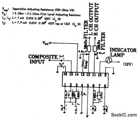
FM stereo demodulator with indicator lamp using an ECG1106 16-pin DIP.Input impedance is 20K,The indicator lamp operates at a 19 kHz input level of 5 mV RMS. Audio muting on voltage is 0.75 volt and off voltage is 1.0 volt(courtesy GTE Sylvania Incorporated). (View)
View full Circuit Diagram | Comments | Reading(647)
AM_FM_F_amplifier_with_AF_amplifier
Published:2009/7/20 3:03:00 Author:Jessie
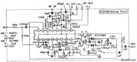
AM/FM F amplifier with AF amplifier.Note in the diagram that the AF amplifier is not connected to the detector output.To use the AF amplifier connect the detector output to the AF input.The AF output with 1 kHz at 1 mV input is 0.47 volt typically(courtesy GTE Sylvania Incorporated). (View)
View full Circuit Diagram | Comments | Reading(681)
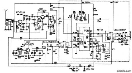
AM_receiver_front_end_with_AM_FM_IF_amplifier_detector_circuit
Published:2009/7/20 3:01:00 Author:Jessie
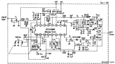
AM receiver front end with AM/FM IF amplifier-detector circuit. FM IF is 10.7 MHz,and the AM IF is 455 kHz.Detector output in FM is between 17 and 76 mV;for AM it is between 14.5 and 42 mV.All coils,transformers,variable capacitor and ceramic filters are standard and can be purchased at Radio Shack(courtesy GTE Sylvania Incorporated). (View)
View full Circuit Diagram | Comments | Reading(4524)
Complete_167_MHz_IF_strip_for_an_FM_tuner_using_four_ECG703A_chips
Published:2009/7/20 2:53:00 Author:Jessie
Complete 16.7 MHz IF strip for an FM tuner using four ECG703A chips(courtesy GTE Sylvania Incorporated). (View)
View full Circuit Diagram | Comments | Reading(634)
FM_IF_amplifier_for_107_MHz
Published:2009/7/20 2:51:00 Author:Jessie
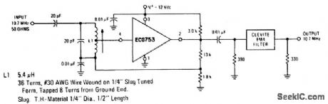
FM IF amplifier for 10.7 MHz (courtesy GTE Sylvania Incorporated). (View)
View full Circuit Diagram | Comments | Reading(649)
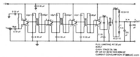
FM_limiting_amplifier_and_Foster_Seeley_discriminator_designed_for_a_107_MHz_IF
Published:2009/7/20 2:51:00 Author:Jessie
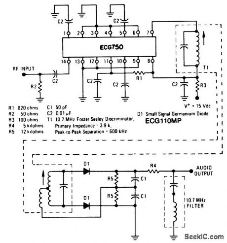
FM limiting amplifier and Foster-Seeley discriminator designed for a 10.7 MHz IF(courtesy GTE Sylvania Incorporated). (View)
View full Circuit Diagram | Comments | Reading(1075)
AM_FM_radio_receiver_without_AF_amplifier_using_an_ECG1003_AM_FM_IF_amplifier
Published:2009/7/20 2:49:00 Author:Jessie


AM/FM radio receiver without AF amplifier using an ECG1003 AM/FM IF amplifier.AM specifications at 1000 kHz are:max sensitivity,26 dB/m;available sensitivity,44.5 dB/m;selectivity,+10 kHz 23 dB,-10 kHz 24 dB.FM specifications at 83 MHz are:max sensitivity,-1 dB PμV;available sensitivity,4.0 dB/μV;-3dB limiting sensitivity,12 dB/m;HFM availdable sensitivity,20dB/μV;3 dB bandwidth,200 kHz;demodulated output,60 mV(courtesy GTE Sylvania Incorporated). (View)
View full Circuit Diagram | Comments | Reading(2913)
ACCURATE_RAMP_GENERATOR
Published:2009/7/9 21:57:00 Author:May
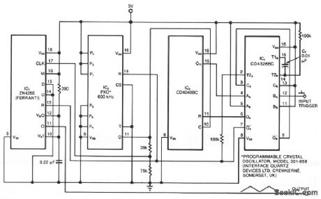
The ramp generator, an inexpensive alternative to commercial function generators, provides a more linear and repeatable output than conventional analog integrators. The circuit provides a triangle waveform in burst mode; in this case, two cycles of 10.24 ms each per input trigger pulse. IC4 is a dual monostable multi ibrator (one shot) in which the A side is configured as a latch (see Multivibrator IC performs extra tasks, EDN, September 6, 1984, p. 232). The rising edge of each input pulse triggers the B side, producing at pin 9 an output pulse whose duration depends on the timing capacitor's, CT, value-A 0.01-μF value gives a 500 μs pulse. This output provides a reset to the A side latch. While the latch is reset withQA, high, QA low, the other three ICs are active. The P1 through P6 connections, as shown, set oscillator IC2's frequency to 50 kHz at pin 11.Counter IC3 counts upward. The output at pin 11 of multifunction converter IC1 ramps up to fullscale, reverses, ramps down to zero, and then repeats this sequence of events. As this output completes its second cycle, IC3 reaches a count of 1024, causing the Q11 output to become high and toggle the IC4 latch. The resulting change of state on QA and QA resets the other three ICs, terminating further activity until the arrival of the next input trigger pulse. IC2 is included for its synchronous-reset capability, and it therefore drives the internal clock of IC1, which cannot be synchronously reset. Still IC2 can be omitted in some applications. The circuit operates from a 5-V supply. You can modify the output by changing IC2's frequency and IC3's output connection. (View)
View full Circuit Diagram | Comments | Reading(1122)
VERY_LOW_DUTY_CYCLE_PULSE_GENERATOR
Published:2009/7/9 21:45:00 Author:May
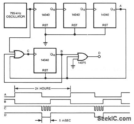
Using a precision oscillator and a few CMOS counters, you can build a precise, very low duty-cycle pulse generator. You can add as many counters as you desire to make the period as long as you wish. The circuit will generate a pulse about 5 ms long every 24 hours-one 5.9 -6% duty cycle (View)
View full Circuit Diagram | Comments | Reading(861)
300_V_PULSE_GENERATOR
Published:2009/7/9 21:44:00 Author:May
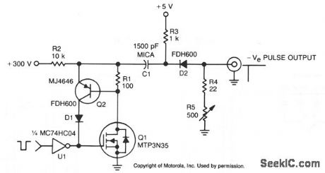
In this TMOS pulser, a negative-going pulse is applied to U1, a high-speed CMOS buffer, which directly drives the gate of Q1, an MTP3N35. If only a 100-V pulse is required, the MTA6N10 can be used.The pulse output across R2 is differentiated by R3/C1 and appears as a negative-going spike at the output terminal. (View)
View full Circuit Diagram | Comments | Reading(702)
WIEN_BRIDGE_OSCILLATOR_CIRCUIT
Published:2009/7/20 4:22:00 Author:Jessie

A 741 op amp is connected to a Wien-bridge, audio-sine-wave oscillator configuration, with C1, C2, R1, and R2 determining the circuit's operating frequency. With the use of NPO capacitors and metal-film resistors, the oscillator's frequency is stable enough for use in tone-control applications. The fixed-frequency oscillator shown can easily be converted into a tunable oscillator by substituting a dual-gang linear potentiometer for R1 and R2. Different frequency ranges can be covered by using other matched values for C1 and C2. Larger values produce lower frequencies, and vice versa for small values. (View)
View full Circuit Diagram | Comments | Reading(0)
THREE_FREQUENCY_AUDIO_OSCILLATOR
Published:2009/7/20 4:20:00 Author:Jessie
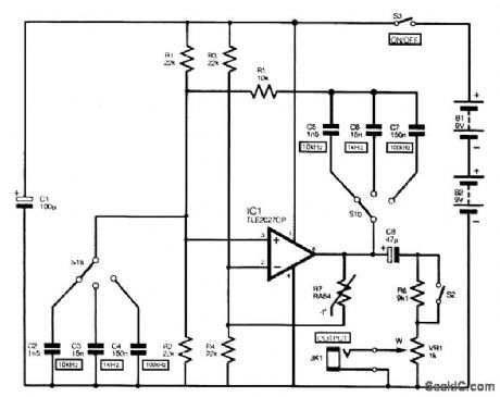
The full circuit diagram for the audio sine-wave generator is shown. Resistors R1 and R2 bias the noninverting (pin 3) input of IC1, and their parallel resistance forms one element of the Wien net-work. They are the equivalent of R1 in Fig. 1. The other resistor in the Wien network is R5. Three switched pairs of capacitors (C2 to C7) provide the unit with its three different output frequencies. Resistors R3 and R4 bias the inverting (pin 2) input of IC1, and their parallel resistance also acts as one element of the negative-feedback network. Thermistor R7 is the other section of the negative-feedback circuit. An RA53 thermistor is the normal choice for this application, but because of its lower cost, an RA54 is used in this circuit. Potentiometer VR1 is the variable-output attenuator. Opening switch S2 introduces losses through resistor R6 that reduce the output by about 20 dB. Use a value of 100 kΩ for R6 if a reduction by about 40 dB is preferred. (View)
View full Circuit Diagram | Comments | Reading(2657)
THREE_TONE_OSCILLATOR
Published:2009/7/20 4:18:00 Author:Jessie
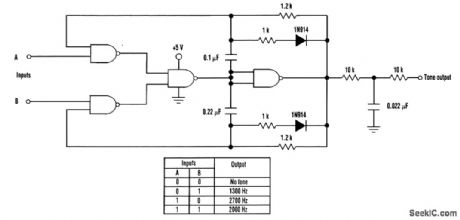
This TTL tone oscillator can generate one of three tones. The tone generation depends on the status of the two input control lines. The design consists of two standard TTL audio tone oscillators merged together using one 7400 TTL chip. Two input lines control the output status. With both inputs low, no output is generated. When input A is high, the high-tone oscillator is gated on. When input B is high, the low-tone oscillator is gated on. With both A and B high, both oscillators are gated on and the output tone generated is midway between the high and low tones. The 1N914 diode in series with a 1-kΩ resistor imposes a 50-percent duty cycle on the waveform. A low-pass filter on the output removes harmonics and mellows the output tone. (View)
View full Circuit Diagram | Comments | Reading(1889)
AUDIO_GENERATOR_CIRCUIT
Published:2009/7/20 4:17:00 Author:Jessie
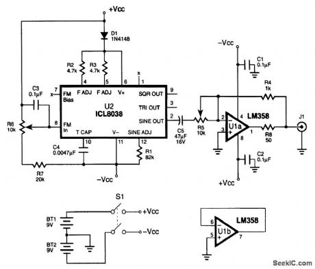
A very compact audio signal generator can be constructed using a precision waveform generator IC (ICL8038) made by Harris Semiconductor. This IC is unique in that it will generate three wave-forms: sine, triangle, and square waves. The frequency output is adjustable between 0.01 Hz and 300 kHz, and the sine-wave output distortion is less than 1 percent. The schematic diagram illustrates the application of the ICL8038 IC to construct a battery-powered mini-audio-signal generator that will provide 500 Hz to 1.5 kHz with adjustable-amplitude output. The output frequency of the generator is set by the combination of R2, R3, and (View)
View full Circuit Diagram | Comments | Reading(7113)
LOW_BATTERY_DETECTOR
Published:2009/7/9 20:55:00 Author:May
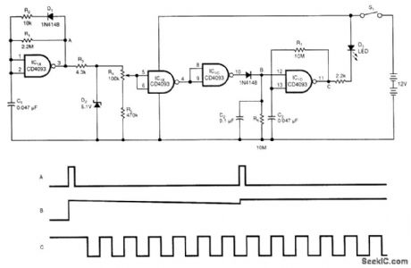
The battery low-voltage detector uses a CD4093 Schmitt trigger and a capacitor that acts as a 1-bit dynamic RAM. The circuit conserves power by using a periodic test method. IC1A, C1, R1, R2, and D1 generate a narrow, positive pulse at point A.
D2, R4, and R5 regulate and divide the signal at A. Thus, the input of IC1B is independent of the power supply. Because the threshold voltage of the Schmitt trigger depends on the power supply, the threshold voltage will drop if the power-supply voltage drops. When the threshold voltage is lower than the input voltage, IC1B will become low, and IC1C's output will become high.
Capacitor C2 stores the results of the periodic test. The time constant C2 and R6 set is 1 s, and the test period is approximately 0.1 s. When point B is high, which implies that the battery is low, IC1D, C3, and R7 generate a square waveform, which lights D3. You can adjust the detected voltage level by adjusting R4. You can test different battery voltages by changing the voltage level of D2. (View)
View full Circuit Diagram | Comments | Reading(0)
| Pages:89/195 At 2081828384858687888990919293949596979899100Under 20 |
Circuit Categories
power supply circuit
Amplifier Circuit
Basic Circuit
LED and Light Circuit
Sensor Circuit
Signal Processing
Electrical Equipment Circuit
Control Circuit
Remote Control Circuit
A/D-D/A Converter Circuit
Audio Circuit
Measuring and Test Circuit
Communication Circuit
Computer-Related Circuit
555 Circuit
Automotive Circuit
Repairing Circuit