
A/D-D/A Converter Circuit
Index 2
HV4205E Single Chip Voltage Converter
Published:2013/10/14 20:04:00 Author:lynne | Keyword: HV4205E Single Chip Voltage Converter
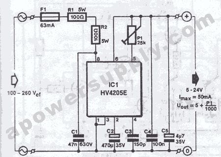
With HV4205E you can build a simple single chip voltage converter. With IC and a few external components connected like in the schematic you can obtain dc stabilized voltages between 5 to 24V directly from main power source (100 to 260V ac). The maximum output current is 50mA.The main chip contains a preregulator which ensure C2 charging voltage (a large capacitance). The charging process continues untill the capacitor voltage has reached a level of approximately the desired voltage + 6V.When this stage is reached, C2 delivers the required voltage to the regulator, the output of this regulator can be adjusted between 5V and 24V with P1 and is available at IC pin 6.
Voltage converter schematic
(View)
View full Circuit Diagram | Comments | Reading(1180)
Trailer Stop & Turn Signal Converter
Published:2013/8/29 1:22:00 Author:lynne | Keyword: Trailer Stop & Turn Signal Converter
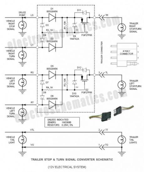
If you ever wondered why your trailer Stop/Turn signal lamps are so dim you are not alone. The answer is simply that the typical Stop & Turn Signal Converter/adapter drops a whopping 2.5V! This is VERY significant on a 12V electrical system. This DIY project provides the information you need build a simple, inexpensive converter that reduces this drop to a mere 0.5V @ 2A, and even has sufficient guts to power a 7.5A load. While this documents the most common 4 way (4 wire) system, it may be easily incorporated into more complex systems.
Most automobiles manufactured today have separate Stop and Turn signals — the stop signals are Red, while the Turn signals are Amber. Unfortunately, most trailers do not include the luxury of amber Turn signals, but use the Stop signal also as a Turn signal. The converter takes both input signals and generates one output signal for the trailer. The logic for accomplishing this is simple, but tricky—check out the following truth table. Curiously, when the Stop and Turn signals are simultaneously applied, the trailer Turn signal is “inverted” so that when the vehicle Turn signal is On, the trailer Turn signal is Off, and vise versa.
(View)
View full Circuit Diagram | Comments | Reading(1364)
12V to 6V Converter with 7805 or LM309
Published:2013/8/19 0:51:00 Author:lynne | Keyword: 12V to 6V Converter with 7805 or LM309
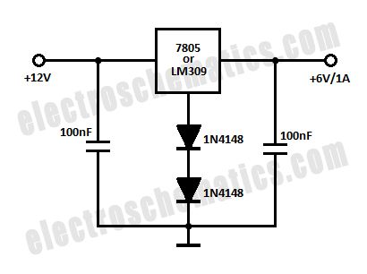
In this schematic is presented a simple 12 Volts to 6 volts converter circuit that is built with the well-known 7805 voltage regulator or the LM309 IC. You can use 7806 as well, but this circuit comes in handy when you do not have a spare 7806.
You can get out a different voltage, for example 7.5V and in this case you have to use 3 or 4 diodes at the GND pin of the IC. The maximum output current will be 1 amp and you need to use a good heatsink.
The actual voltage might be different, for example using 2 diodes as shown in the schematic can give an output voltage of 6.5V and using one diode will result in a 6V output. It is better to assemble the circuit on a protoboard (breadboard) and test.
(View)
View full Circuit Diagram | Comments | Reading(3088)
26V-to-5000V DC-DC Converter circuit
Published:2013/3/29 4:34:00 Author:Ecco | Keyword: 26V-to-5000V, DC-DC Converter
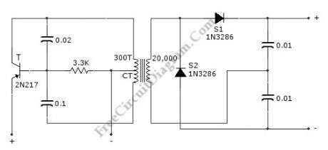
This circuit can provide 5,000 VDC from 26 VDC. This circuit has ripple of under 0.01% due to Voltage-doubling capacitors. As sinusoidal oscillator, a 2N217 transistor is used. The diode and the capacitors at the output stage should be of high voltage type. Here is the schematic diagram of the circuit:
(View)
View full Circuit Diagram | Comments | Reading(2184)
12-bit A / D conversion system circuit of AD585
Published:2013/1/30 1:43:00 Author:Ecco | Keyword: 12-bit , A / D conversion system
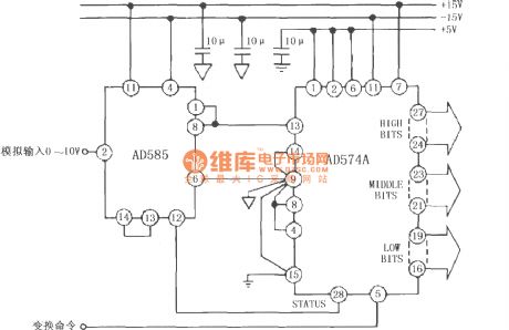
AD585 has a fast sampling time, therefore it can be applied to multi-channel data acquisition system, and it can complete the A / D conversion with high-frequency signal and high passing rate.
(View)
View full Circuit Diagram | Comments | Reading(1635)
AD7543 12 - bit D / A converter
Published:2013/1/25 1:01:00 Author:Ecco | Keyword: 12 - bit D / A converter
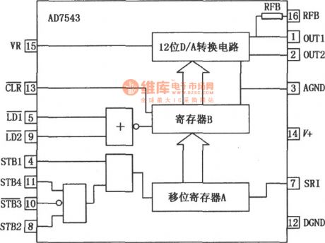
AD7543 has serial input and slower number passing, but the desired signal wiring is less, and it is convenient for optocoupler isolation, it is suitable for telecommunication applications, therefore, it is easily connected with the microcontroller. Similar model: MP7543, and its reference voltage is supplied by an external voltage. AD7543's pinout and internal block diagram is shown as figure:
(View)
View full Circuit Diagram | Comments | Reading(1092)
Two channel A-to-D converter
Published:2013/1/25 1:19:00 Author:muriel | Keyword: Two channel, A-to-D converter
View full Circuit Diagram | Comments | Reading(1065)
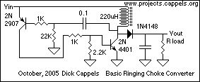
basic converter
Published:2013/1/22 21:21:00 Author:muriel | Keyword: basic converter
View full Circuit Diagram | Comments | Reading(1388)
5 volt to +24V flyback output DC to DC Converter
Published:2013/1/22 21:21:00 Author:muriel | Keyword: 5 volt to +24V , flyback output, DC to DC Converter
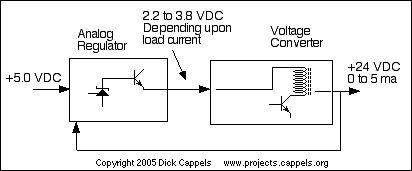
View full Circuit Diagram | Comments | Reading(1279)
Synchronous Demodulator and A-to-D Converter
Published:2013/1/22 21:12:00 Author:muriel | Keyword: Synchronous Demodulator, A-to-D Converter
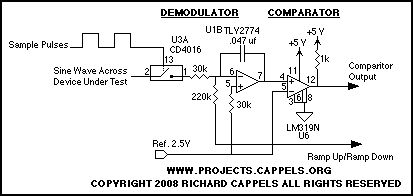
View full Circuit Diagram | Comments | Reading(3257)
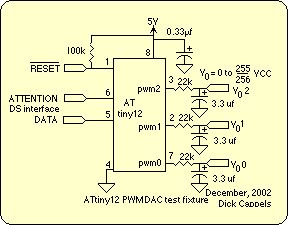
three-channel DAC
Published:2013/1/22 20:59:00 Author:muriel | Keyword: three-channel, DAC
View full Circuit Diagram | Comments | Reading(943)
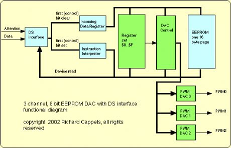
3 channel, 8 bit EEPROM DAC
Published:2013/1/22 20:58:00 Author:muriel | Keyword: 3 channel, 8 bit, EEPROM DAC
View full Circuit Diagram | Comments | Reading(1086)
HDAC7542 12 - bit parallel port D / A converter
Published:2013/1/22 2:48:00 Author:Ecco | Keyword: 12 - bit, parallel port, D / A converter

HDAC7542 can be directly matched with CPU, and it is a low-power, high-speed, high - gain 12-bit multiplying D / A converter. The digital signal is divided into 3 groups which is input tp memory by 4 bytes, and its internal data is written to the D / A converter after passing cache twice, then the D / A converter output is updated for four-quadrant multiplication. Its typical application circuit is shown as figure. Figure (A) shows the unipolar 2-quadrant multiplying connection.
(View)
View full Circuit Diagram | Comments | Reading(1252)
The voltage DAC0800 conversion circuit from current output D/A
Published:2012/11/29 0:28:00 Author:Ecco | Keyword: voltage, conversion , current output D/A
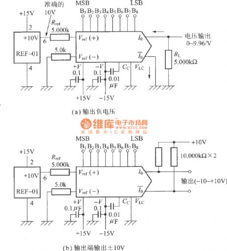
Figure a outputs negative voltage; The output end ofthe circuit shown inFigure b outputs ±10V.
(View)
View full Circuit Diagram | Comments | Reading(3004)
The directly driving capacitive input A / D converter circuit diagram with INA321/322
Published:2012/11/9 19:36:00 Author:Ecco | Keyword: directly driving , capacitive input , A / D converter
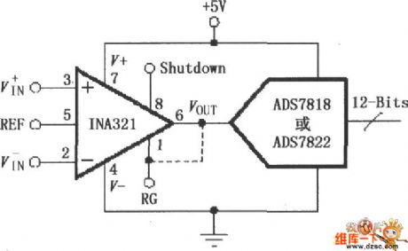
Due the INA321/322 output is in low in resistance, the high-frequency work can directly drive capacitive loads. Input voltage is amplified and output by INA321/322, then it is sent to the 12 - bit high - speed low-power sampling A / D converter ADS7818 or ADS7822. ADS7818 or ADS7822 internal input terminal is the capacitor array (CDAC) digital-analog converter, that is a capacitive input, A / D converter converts the input analog signal to 12-bit digital signal output.
(View)
View full Circuit Diagram | Comments | Reading(1014)
3V to 9V DC Converters
Published:2012/9/18 21:30:00 Author:Ecco | Keyword: 3V to 9V, DC Converter
Here are some 3V to 9V DC converter circuits that were requested by some of our visitors. It may be helpful to have one of this converters when no 9V battery is available or if you consider that they are too expensive. The first circuit is very simple, it uses the TL496 power supply controller, a coil and a electrolytic capacitor.TL496 3 to 9 volt converter circuit
The maximum output voltage is actually 8.6V and current is around 80mA.The input current (the current drawn from the batteries) is 405mA at the maximum output current. Without load the current consumption is 125µA and the batteries life is around 166 days.
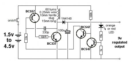
Here is another 1.5… 4.5V to 9V converter
3 volt to 9 volt with LMC555This dc converter is built with the CMOS version of 555 timer. You can get 12V too if you change the zener diode to a 12V version.
Probably there are more 3 to 9 volt dc converters but for the moment those are the only ones presented in this article.
2 Responses to “3V to 9V DC Converters”
(View)
View full Circuit Diagram | Comments | Reading(3654)
Light to Frequency Converter TSL220
Published:2012/9/12 21:04:00 Author:Ecco | Keyword: Light to Frequency, Converter
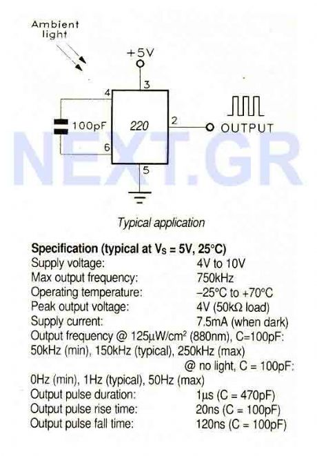
A large area photodiode and current to frequency converter combined in a clear plastic 8-pin DIL package. The output is a pulse train whose frequency is directly proportional to the light intensity. The output is CMOS compatible (use a 3k3 pulldown resistor to drive LS TTL) and the frequency can be measured by pulse counting, period timing or integration techniques. The photodiode has a wide dynamic range, high sensitivity and high noise immunity.
Source: NEXT.GR (View)
View full Circuit Diagram | Comments | Reading(1151)
Video speed 6-bit Flash A/D converter
Published:2012/9/12 21:00:00 Author:Ecco | Keyword: Video speed , 6-bit, Flash, A/D converter
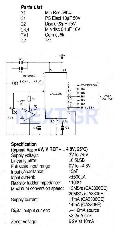
This circuit use the CA3306 a family of CMOS parallel (flash) analogue to digital converters designed for low power, high speed applications. The CA3306CE operates at sampling rates up to 10 million samples per second and the CA3306E up to 15 million samples per second permitting analogue signals with bandwidths up to 5MHz or 7.5MHz to be fully digitised to 6-bit accuracy.
Source: NEXT.GR (View)
View full Circuit Diagram | Comments | Reading(1374)
2 to 4 wire audio converter
Published:2012/9/11 21:24:00 Author:Ecco | Keyword: 2 to 4 wire, audio converter
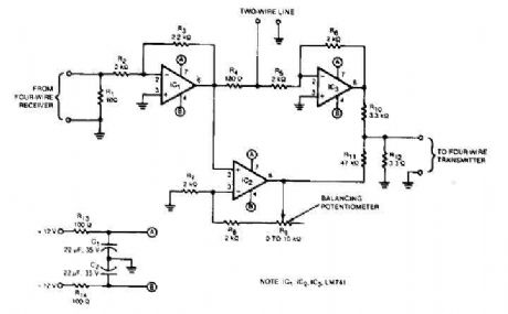
This audio converter circuit maintains 40 dB of isolation between the two halves of entry and exit of a four-line son, while allowing a line connecting two son. A balancing potentiometer, R, adjusts the gain of zero lC2to crossing the inlet to the outlet. (View)
View full Circuit Diagram | Comments | Reading(0)
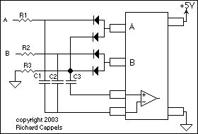
Analogue to digital converter circuit
Published:2012/9/11 21:19:00 Author:Ecco | Keyword: Analogue to digital, converter
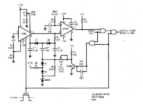
That simple 4 digits converter circuit has OUTPUT COUNT = 1 according to my f-IMHz to 10.000. All diodes are IN4146 POLYSTYRENE NPO. (View)
View full Circuit Diagram | Comments | Reading(3848)
| Pages:2/24 1234567891011121314151617181920Under 20 |
Circuit Categories
power supply circuit
Amplifier Circuit
Basic Circuit
LED and Light Circuit
Sensor Circuit
Signal Processing
Electrical Equipment Circuit
Control Circuit
Remote Control Circuit
A/D-D/A Converter Circuit
Audio Circuit
Measuring and Test Circuit
Communication Circuit
Computer-Related Circuit
555 Circuit
Automotive Circuit
Repairing Circuit