
A/D-D/A Converter Circuit
Index 7
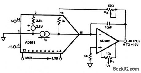
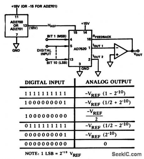
10_bit_D_A_converter_connected_for_four_quadrant_multiplication_
Published:2009/7/20 4:17:00 Author:Jessie
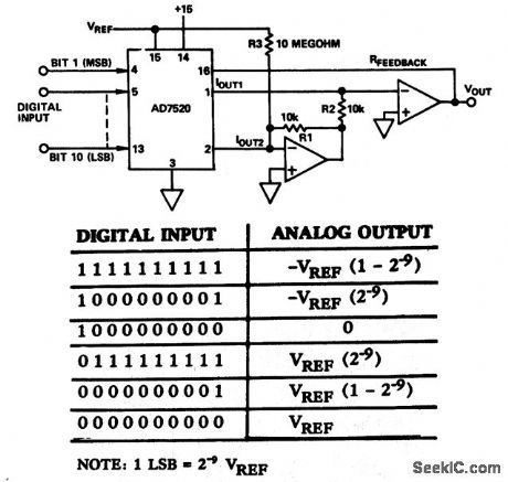
10-bit D/A converter connected for four-quadrant multiplication (courtesy Analog Devices, Inc.). (View)
View full Circuit Diagram | Comments | Reading(863)
12_bit_successive_approximation_A_D_converter_for_unipolar_0_to__10_volt_input_range_with_buffer_follower
Published:2009/7/20 4:16:00 Author:Jessie

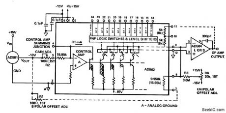
12-bit successive approximation A/D converter for unipolar 0 to +10-volt input range with buffer follower. A/D chip is the AD572 (courtesy Analog Devices, Inc.). (View)
View full Circuit Diagram | Comments | Reading(933)
V_F_converter_with_20_kHz_full_scale_output
Published:2009/7/20 4:15:00 Author:Jessie
V/F converter with 20 kHz full scale output (courtesy Analog Devices, Inc.). (View)
View full Circuit Diagram | Comments | Reading(951)
A_D_converter_with_sample_and_hold_circuit_for_bipolar_operation±5_volts
Published:2009/7/20 4:14:00 Author:Jessie
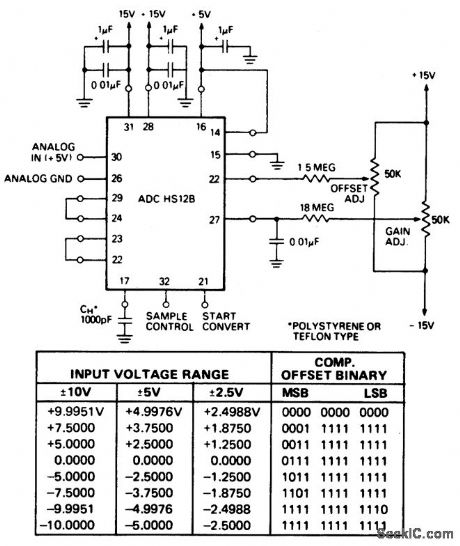
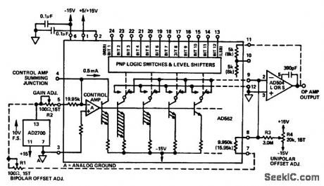
A/D converter with sample-and-hold circuit for bipolar operation,±5 volts. For ±2.5-volt operation jumper pins 22 and 25 with the connections shown. For ±10-volt operation change the jumper at pin 29 from pin 24 to pin 25 and leave all otters as shown (courtesy Datel Systems, Inc.). (View)
View full Circuit Diagram | Comments | Reading(943)
10_bit_and_sign_multiplying_D_A_converter_
Published:2009/7/20 4:13:00 Author:Jessie
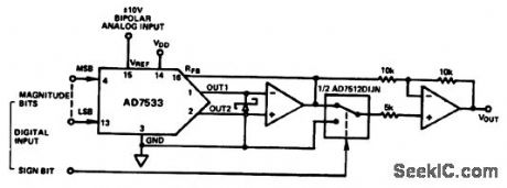
10-bit and sign multiplying D/A converter (courtesy Analog Devices, Inc.). (View)
View full Circuit Diagram | Comments | Reading(843)
10_bit_D_A_converter_with_0_to__10_volt_unipolar_output
Published:2009/7/20 4:12:00 Author:Jessie
10-bit D/A converter with 0 to +10-volt unipolar output (courtesy Analog Devices, Inc.). (View)
View full Circuit Diagram | Comments | Reading(953)
Digital_gain_control_of_a_12_bit_successive_approximation_A_D_convener_using_an_AD559_8_bit_D_A_converter
Published:2009/7/20 4:05:00 Author:Jessie

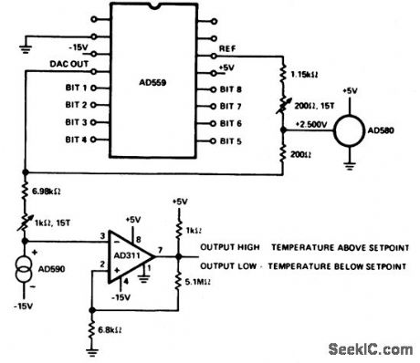
Digital gain control of a 12-bit successive approximation A/D convener (AD572) using an AD559 8-bit D/A converter (courtesy Analog Devices, Inc.). (View)
View full Circuit Diagram | Comments | Reading(886)
CMOS_A_D_converter_with__10_volt_reference
Published:2009/7/20 4:04:00 Author:Jessie
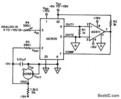
CMOS A/D converter with -10 volt reference (courtesy Analog Devices, Inc.). (View)
View full Circuit Diagram | Comments | Reading(1017)
8_bit_D_A_convertor_with_unipolar_output
Published:2009/7/20 4:03:00 Author:Jessie
8-bit D/A convertor with unipolar output (courtesy Analog Devices, Inc.). (View)
View full Circuit Diagram | Comments | Reading(915)
10_bit_D_A_converter_with_precision_low_noise_reference
Published:2009/7/20 4:03:00 Author:Jessie
10-bit D/A converter with precision low-noise reference (courtesy Analog Devices, Inc.). (View)
View full Circuit Diagram | Comments | Reading(908)
12_bit_D_A_converter_with_precision_10_volt_reference
Published:2009/7/20 4:02:00 Author:Jessie
12-bit D/A converter with precision 10-volt reference (courtesy Analog Devices, Inc.). (View)
View full Circuit Diagram | Comments | Reading(907)
Precision_12_bit_D_A_converter
Published:2009/7/20 4:01:00 Author:Jessie
Precision 12-bit D/A-converter (courtesy Analog Devices, Inc.). (View)
View full Circuit Diagram | Comments | Reading(0)
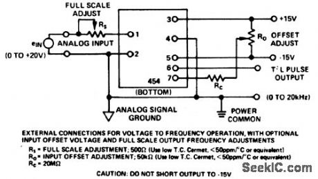
Voltage_to_frequency_converter_for_bipolar_operation
Published:2009/7/20 3:58:00 Author:Jessie

Voltage-to-frequency converter for bipolar operation. Full scale output is 20 kHz.Chip used is the Datel VFQ-1 14-pin DIP.outputs at fo and fo/2 are possible(courtesy Datel Systems, Inc.). (View)
View full Circuit Diagram | Comments | Reading(962)
8_bit_D_A_convertor_with_digitally_controlled_set_point
Published:2009/7/20 3:57:00 Author:Jessie
8-bit D/A convertor with digitally controlled set point(courtesy Analog Devices, Inc.). (View)
View full Circuit Diagram | Comments | Reading(1146)
Temperature_to_frequency_convener_using_a_Datel_VFQ_1_14_pin_DIP_
Published:2009/7/20 3:56:00 Author:Jessie
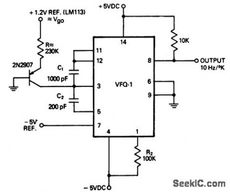
Temperature-to-frequency convener using a Datel VFQ-1 14-pin DIP (courtesy Datel Systems, Inc.). (View)
View full Circuit Diagram | Comments | Reading(975)
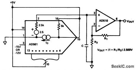
D_A_converter_with_10_volt_reference
Published:2009/7/20 3:55:00 Author:Jessie
D/A converter with 10-volt reference (courtesy Analog Dodoes, Inc.). (View)
View full Circuit Diagram | Comments | Reading(930)
10_bit_D_A_converter_connected_for_two_quadrant_multiplication_
Published:2009/7/20 3:54:00 Author:Jessie
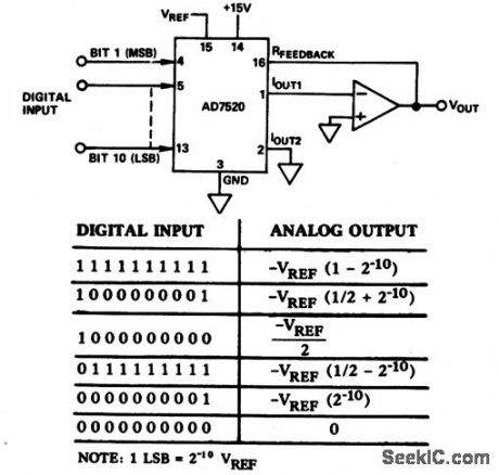
10-bit D/A converter connected for two-quadrant multiplication (courtesy Analog Devices, Inc.). (View)
View full Circuit Diagram | Comments | Reading(839)
A_D_converter
Published:2009/7/20 3:54:00 Author:Jessie
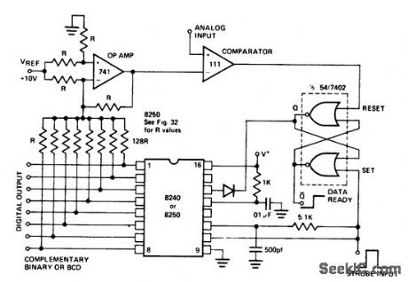
A/D converter.The circuit shown is an 8-bit binary A/D converter when using the 8240 or a 2-digit BCD A/D converter when using the 8250.The input strobe first resets then triggers the 8240/8250 and set the flip-flop,which enables the counter. The stair case from the op amp counts down until reaches the analog input, at which time the comparator resets the flip-flop and stops the count,The digital word at the eight outputs is the complementary binary or BCD equivalent of the analog input.As shown the maximum conversion time is 2.6 ms,determined by R and c at pin 14 of the counter.The not-Q output of the flip-flop is convenient to use as a data ready flag since it is high when conversion is complete(courtesy Intersil, Inc.). (View)
View full Circuit Diagram | Comments | Reading(0)
Celsius_temperature_to_frequency_converter
Published:2009/7/20 3:52:00 Author:Jessie
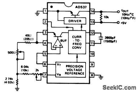
Celsius (Fahrenheit) temperature-to-frequency converter. No sensor is required since the AD537 has an internal VTEMP output. The converter output tracks the temperature at a rate of 10 hertz per degree Celsius or Fahrenheit, depending on the resistor-capacitor values chosen. All values in parentheses are for Fahrenheit. To calibrate measure the room temperature in Kelvin. Measure the temperature output at pin 6 at that temperature. Calculate the offset adjustment by dividing the VTEMP at pin 6 in milli volts by the room temperature in Kelvin, then multiplying by 273.2 The offset voltage will be in milli volts. Then disconnect the 49-ohm resistor and adjust the 2K pot for the offset voltage at pin 7. Connect the 49dm resistor. Then adjust the 500-ohm slope trimmer for room temperature, or 25℃, which results in 250 hertz (courtesy Analog Devices, Inc.). (View)
View full Circuit Diagram | Comments | Reading(1062)
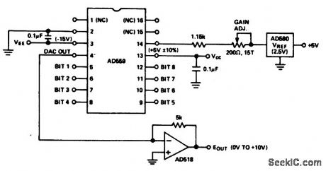
Digital_4_to_20_mA_or_1_to_5_volt_converter_
Published:2009/7/20 3:51:00 Author:Jessie
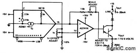
Digital 4-to-20 mA or 1-to-5 volt converter (courtesy Analog Devices, Inc.). (View)
View full Circuit Diagram | Comments | Reading(879)
| Pages:7/24 1234567891011121314151617181920Under 20 |
Circuit Categories
power supply circuit
Amplifier Circuit
Basic Circuit
LED and Light Circuit
Sensor Circuit
Signal Processing
Electrical Equipment Circuit
Control Circuit
Remote Control Circuit
A/D-D/A Converter Circuit
Audio Circuit
Measuring and Test Circuit
Communication Circuit
Computer-Related Circuit
555 Circuit
Automotive Circuit
Repairing Circuit