
A/D-D/A Converter Circuit
Index 10
D_A_convener_with_fast_bipolar_output_using_the_Datel_DAC_IC_10BC_and_AM_452
Published:2009/7/20 5:26:00 Author:Jessie
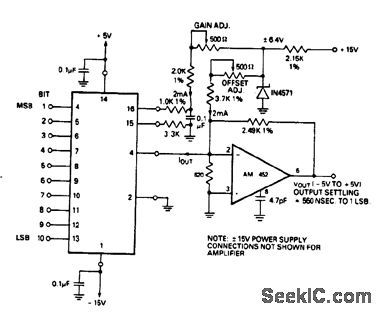
D/A convener with fast bipolar output using the Datel DAC-IC 10BC and AM-452.See coding table(courtesy Datel Systems, Inc.). (View)
View full Circuit Diagram | Comments | Reading(1050)
D_A_convertner_in_bipolar_operation
Published:2009/7/20 5:25:00 Author:Jessie
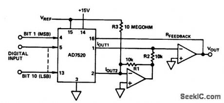
D/A convertner in bipolar operation (courtesy Analog Devices, Inc.). (View)
View full Circuit Diagram | Comments | Reading(893)
D_A_converer_With_fast_unipolar_output_using_the_AM_452
Published:2009/7/20 5:24:00 Author:Jessie
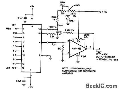
D/A converer With fast unipolar output using the AM-452(courtesy Datel Systems, Inc.). (View)
View full Circuit Diagram | Comments | Reading(935)
A_D_divider_using_an_AD7520_10_bit_multiplying_D_A_converter
Published:2009/7/20 5:24:00 Author:Jessie
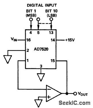
A/D divider using an AD7520 10-bit multiplying D/A converter (courtesy Analog Devices, Inc.). (View)
View full Circuit Diagram | Comments | Reading(845)
8_bit_buffered_multiplying_CMOS_D_A_convener_in_unipolar_binary_operation_
Published:2009/7/20 5:23:00 Author:Jessie
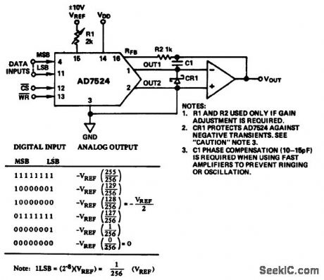
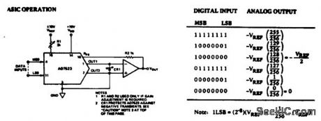
8-bit buffered multiplying CMOS D/A convener in unipolar binary operation (courtesy Analog Devices, Inc.). (View)
View full Circuit Diagram | Comments | Reading(850)
10_bit_multiplying_D_A_converter_in_unipolar_operation
Published:2009/7/20 5:23:00 Author:Jessie
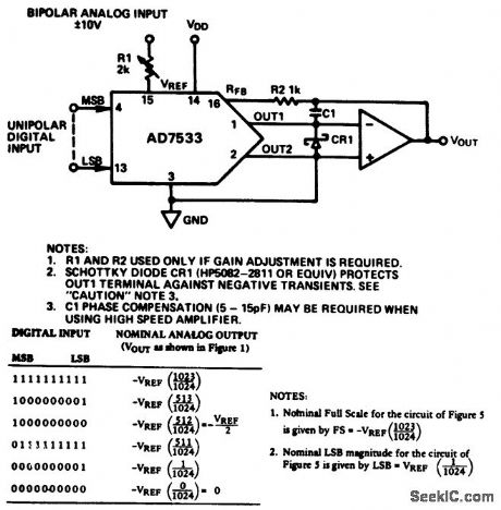
10-bit multiplying D/A converter in unipolar operation(courtesy Analog Devices, Inc.). (View)
View full Circuit Diagram | Comments | Reading(857)
10_bit_CMOS_A_D_converter_in_bipolar_operation
Published:2009/7/20 5:22:00 Author:Jessie
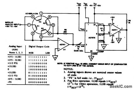
10-bit CMOS A/D converter in bipolar (offset binary) operation. This is a modified 2s complement operation (courtesy Analog Devices, Inc.). (View)
View full Circuit Diagram | Comments | Reading(860)
8_bit_multiplying_D_A_convener_in_unipolar_binary_operation_below
Published:2009/7/20 5:21:00 Author:Jessie
8-bit multiplying D/A convener in unipolar binary operation below (courtesy Analog Devices, Inc.). (View)
View full Circuit Diagram | Comments | Reading(788)
Serial_gray_to_binary_converter_above
Published:2009/7/20 5:20:00 Author:Jessie
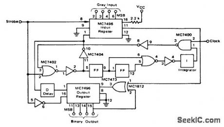
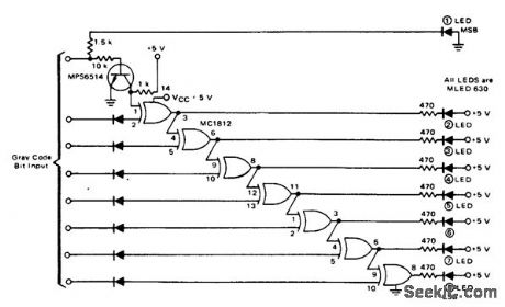
Serial gray-to-binary converter above (courtesy Motorola Semiconductor Products Inc.). (View)
View full Circuit Diagram | Comments | Reading(1010)
8_bit_A_D_converter_using_an_ADC_MC8B_16_pin_DIP
Published:2009/7/20 5:18:00 Author:Jessie
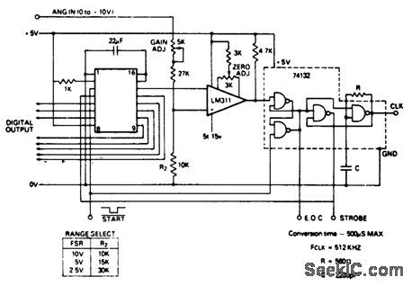
8-bit A/D converter using an ADC-MC8B 16-pin DIP. Pin functions of the Datel ADC-MC8B chip are as follows: pin 1, ground; pin 2, logic select; pin 3, reset; pin 4, strobe; pin5, bit8 (LSB); pin6, bit7; pin7, bit6;pin8, +VCC; pin 9, bit 5; pin 10, bit4; pin 11, bit3; pin 12, bit2; pin 13, bit 1(MSB); pin 14, analog out; pin 15,VREF input; pin 16, VREF output. To calibrate, apply continous start commands to the start input. For the zero adjustment ground the analog input and vary the zero adjust pot until the LSB flickers between one and zero with all other inputs at logic zero. For the gain adjustment apply FS-1/2 LSB to the analog input and vary the gain adjust pot until LSB flickers between one and zero with all other bits at logic one (courtesy Datel Systems, Inc.). (View)
View full Circuit Diagram | Comments | Reading(1361)
8_bit_successive_approximation_A_D_converter
Published:2009/7/20 5:17:00 Author:Jessie
8-bit successive-approximation A/D converter (courtesy Motorola Semiconductor Products Inc.). (View)
View full Circuit Diagram | Comments | Reading(2638)
High_speed_8_bit_successive_approximation_A_D_convener
Published:2009/7/20 5:16:00 Author:Jessie
High-speed 8-bit successive-approximation A/D convener (courtesy Motorola Semiconductor Products Inc.). (View)
View full Circuit Diagram | Comments | Reading(890)
D_A_convener_with_output_buffer
Published:2009/7/20 5:14:00 Author:Jessie
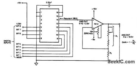
D/A convener with output buffer. VOUT is directly proportional to the digital input.R2 should be less than or equal to 650K to assure good temperature compensation. Metal film 1% resistors and 100 PPM/℃ trimmers are recommended. For fast settling time use a Datel AM-452 buffer. To calibrate apply continuous start commands to the start input (pin 3). Set all bits to logic zero and vary the zero adjust pot until VOUT is zero. Set all bits to logic one and vary the gain adjust pot until VOUT is equal to the nominal FS-1 LSB, where LSB is equal to FSR/256 (courtesy Datel Systems, Inc.). (View)
View full Circuit Diagram | Comments | Reading(889)
Cyclic_converter
Published:2009/7/20 5:13:00 Author:Jessie

Cyclic converter (courtesy Motorola Semiconductor Products Inc.). (View)
View full Circuit Diagram | Comments | Reading(0)
4_1_2_digit_2000_volt_A_D_converter_with_LED_readout_using_the_8052A_7103A_digital_pair
Published:2009/7/20 5:12:00 Author:Jessie
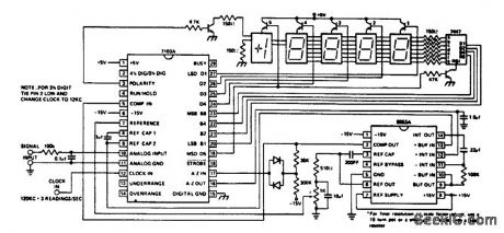
4 1/2-digit (2.000-volt) A/D converter with LED readout using the 8052A/7103A digital pair (courtesy Intersil, Inc.). (View)
View full Circuit Diagram | Comments | Reading(1168)
Parallel_gray_to_binary_converter
Published:2009/7/20 5:10:00 Author:Jessie
Parallel gray-to-binary converter(courtesy Motorola Semiconductor Products Inc.). (View)
View full Circuit Diagram | Comments | Reading(1639)
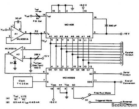
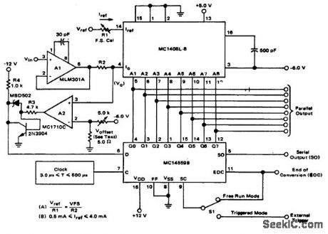
8_bit_multiplying_D_A__converter_In_bipolar_operation
Published:2009/7/20 5:09:00 Author:Jessie
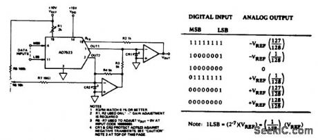
8-bit multiplying D/A converter In bipolar operation(courtesy Analog Devices, Inc.). (View)
View full Circuit Diagram | Comments | Reading(844)
Twelve_10_bit_CMOS_A_D_converters_onto_a_data_bus
Published:2009/7/20 5:09:00 Author:Jessie
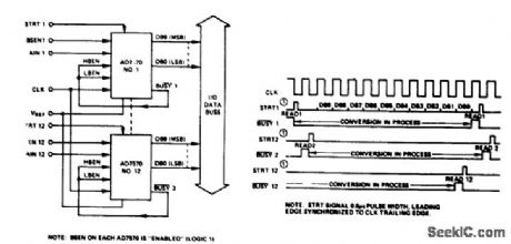
Twelve 10-bit CMOS A/D converters onto a data bus (courtesy Analog Devices, Inc.). (View)
View full Circuit Diagram | Comments | Reading(834)
10_bit_CMOS_A_D_converter_in_unipolar_binary_operation_
Published:2009/7/20 5:08:00 Author:Jessie
10-bit CMOS A/D converter in unipolar binary operation (courtesy Analog Devices, Inc.). (View)
View full Circuit Diagram | Comments | Reading(958)
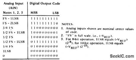
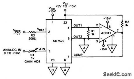
IF_POSITIVE_VSUBREF_SUB_IS_USED
Published:2009/7/20 5:06:00 Author:Jessie

IF POSITIVE VREF IS USED.THE ANALOG INPUT RANGE IA 0 TO-VREF,AND THE COMPARTOR'S㈠ INPUT SHOULD BE CONNECTED TO OUT1(PIN 4) OF THE AD7570. (View)
View full Circuit Diagram | Comments | Reading(936)
| Pages:10/24 1234567891011121314151617181920Under 20 |
Circuit Categories
power supply circuit
Amplifier Circuit
Basic Circuit
LED and Light Circuit
Sensor Circuit
Signal Processing
Electrical Equipment Circuit
Control Circuit
Remote Control Circuit
A/D-D/A Converter Circuit
Audio Circuit
Measuring and Test Circuit
Communication Circuit
Computer-Related Circuit
555 Circuit
Automotive Circuit
Repairing Circuit