
Index 149
5_V_SUPPLY_INCLUDING_STABILIZED_MOMENTARY_BACKUP
Published:2009/7/2 2:50:00 Author:May
Circuit Notes
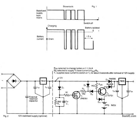
This circuit protects microprocessor systems from“brownouts”without the expense of an uninterruptible power supply. Designed around a small 9-V nickel cadmium battery the circuit continues to provide a constant 5-V output during brownouts of up to a few seconds, Load currents of up to 500 mA may be drawn using the components shown.With this mains-derived supply present, D5 is forward biased so that the stabilized sup-ply powers the 5-V regulator and hence the circuitry to be protected. FET Ty is held on by D1, its drain current being provided from the dc supply via Rb and D2. Diode D3 is reverse-biased so that T2 is off, and the battery is isolated from D6. RCH and D4 serve to trickle charge the battery with approximately 1.2 mA.When the 12-V supply is removed, RI and C1 initially keep T1 switched on. D3 is now forward biased, so that T1 drain current is drawn via Rb, D3 and T2 from the battery. This switches T2 on, allowing the load circuitry to draw current from the battery via D6 and the 5-V regulator. After a few seconds C1 has discharged (via RI) such that Vgs falls below thq threshold value for the FET, and T1 switches off. There is then no path for T2 base current, so that it also switches off, isolating the battery. (View)
View full Circuit Diagram | Comments | Reading(670)
Flash_memory_programming_supply_30_mA
Published:2009/7/24 2:38:00 Author:Jessie
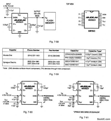
Figure 7-58 shows a MAX662A connected to provide a +12-V, 30-mA output for programming byte-wide flash memories. Figure 7-59 shows component suppliers. Figures 7-60 and 7-61 show connections for programming commercial-temperature range, and extended /military-range applications, respectively. Quiescent current is 185 μA, with 0.5-μA shutdown current. The IC has a logic-controlled shutdown pin that allows direct microprocessor control. MAXIM NEW RELEASES DATA BOOk, 1995, P. 4-75, 4-79. (View)
View full Circuit Diagram | Comments | Reading(703)
Battery_level_indicator_with_a_regulated_LED_current
Published:2009/7/24 2:36:00 Author:Jessie
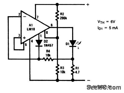
This circuit also regulates current through the LED so that adequate current is available at minimum voltage, but excessive current is not drawn at maximum voltage. Minimum threshold voltage is limited by LED bias (typically 1.7 V for red, 2 V for green and 2.5 V for yellow). With a red LED, the threshold can be reduced to about 2 V. The threshold voltage is 6 V for the resistor values shown. (View)
View full Circuit Diagram | Comments | Reading(716)
_5_V__12_V__15_V_high_efficiency_inverter
Published:2009/7/24 2:46:00 Author:Jessie


Figure 7-64 shows the NlAX764/65/66 connected to provide inverter operationwith fixed. utput voltages.Figure 7-65 shows component suppliers. MAXIM NEWRELEASES DATA Book, 1995,P. 4-121 4-123. (View)
View full Circuit Diagram | Comments | Reading(736)
UNINTERRUPTIBLE_POWER_SUPPLY_FOR_PERSONAL_COMPUTERS
Published:2009/7/2 2:05:00 Author:May
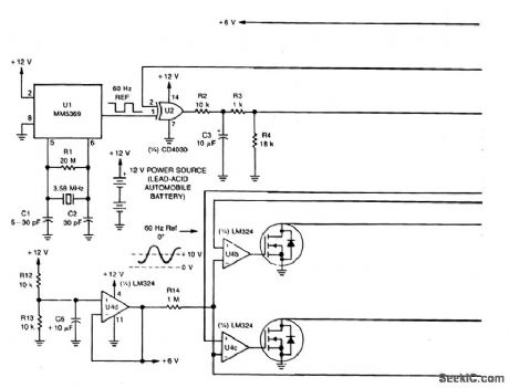
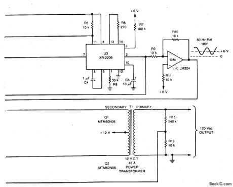
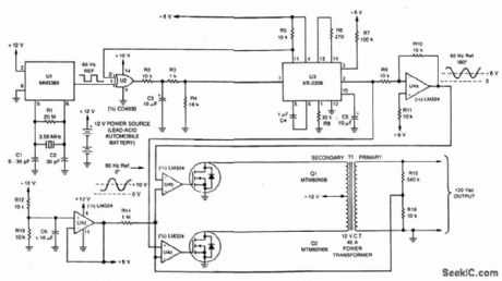
Circuit NotesThe UPS is basically an ac inverter that is powered by a 12-V, lead-acid automobile battery. During power outages, it can supply several minutes of power for an average personal computer. It incorporates a crystal-controlled 60 Hz time base, so that a computer with a real time clock can maintain its accuracy. It isolates the ac line from the computer, so it can be used to operate sensitive electronic equipment on noisy power sources.Two MTM60N06 Power FETs (Q1 and Q2) alternately switch current through a center-tapped 120-V to 12-V filament transformer (T1) with its primary and secondary reversed. The 120-V output is compared with a 60 Hz reference in a closed-loop configuration that maintains a constant output at optimum efficiency.A 60 Hz reference frequency is derived from a crystal oscillator and divider circuit, UI. An inexpensive 3.58 MHz color burst crystal provides the time base that can be accurately adjusted by C1. The 60 Hz output from U1 is applied to the exclusive-OR gate, U2, and then to the XR-2206 function generator (U3) that converts the square wave into a she wave. U2 and U3 form a phase-locked loop that synchronizes the sine wave output o f U3 with the 60 Hz square wave reference of U1. The she wave is then inverted by op amp U4a, so that two signals 180 out of phase can be applied to U4b and U4c that drive Q1 and Q2. Due to the closed-loop configuration of the drive circuits, Q1 and Q2 conduct only during the upper half of the sine wave. Therefore, one TMOS device conducts during the first half of the sine wave and the other conducts during the second half. (View)
View full Circuit Diagram | Comments | Reading(5068)
8_AMP_REGULATED_POWER_SUPPLY_FOR_OPERATING_MOBILE_EQUIPMENT
Published:2009/7/2 1:45:00 Author:May
Circuit Notes
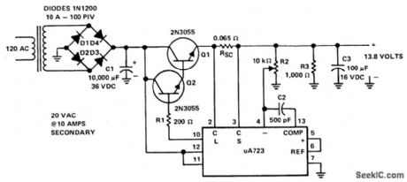
This supply is powered by a transformer operating from 120 Vac on the primary and providing approximately 20 Vac on the primary, and providing approximately 20 Vac on the secondary. Four 10-A diodes with a 100 PIV rating are used in a full-wave bridge rectifier. A 10,000 μF/36 Vdc capacitor completes the filtering, providing 28 Vdc. The dc voltage is fed to the collectors of the Darlington connected 2N3055's, Base drive for the pass tfansistors is from pin 10 of the μA723 through a 200 ohm current limiting resistor, R1. The reference terminal (pin 6) is tied directly to the noninverting input of the error amplifter (pin 5), providing 7.15 V for comparison.
The inverting input to the error amplifier(pin 4) is fed from the center arm of a 10 k ohm potentiometer connected across the output of the supply. This control is set for the desired output voltage of 13.8 V. Compensation of the error amplifier is accom-plished with a 500 pF capacitor connected from pin 13 to pin zL. If the power supply should exceed 8 A or develop a short circuit, the μA723 regulator will bias the transistors to cutoff and the output voltage will drop to near zero until the short circuit condition is corrected.
(View)
View full Circuit Diagram | Comments | Reading(916)
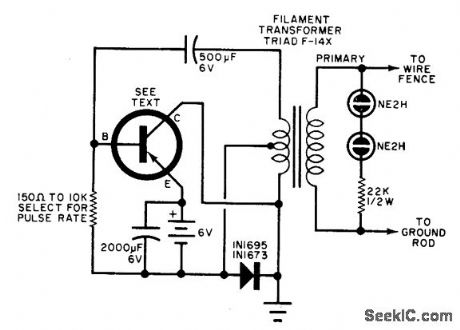
SOLID_STATE_ELECTRIC_FENCE_CHARGER
Published:2009/7/1 23:29:00 Author:May
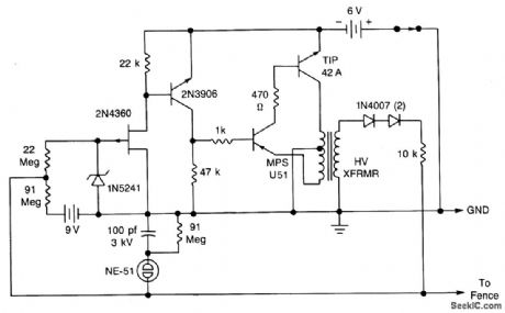
A touch-sensing circuit keeps the high-voltage generator cut off until something touches the fence wire. Contact with the fence sensing circuit wire starts the high-voltage generator which applies a series of 500 microsecond puises at approximately 300 volts to the fence wire. Pulse repetition rate is determined by the intruder's resistance to earth ground. The lower the resistance, the higher the pulse rate. A ground rod is inserted several inches into the ground near the fence wire. In the sensing mode the neon lamp should not flicker or light. If it does, it indicates leakage between the fence wire and ground. If sensitivity is too great, it can be reduced by changing the 91 Meg resistor to 47 or 22 Meg as required. (View)
View full Circuit Diagram | Comments | Reading(5357)
ELECTRIC_FENCE_CHARGER
Published:2009/7/1 23:25:00 Author:May
Any good power transistor can be used in this circuit. The base resistor should be adjusted to obtain a pulse rate of about 50 pulses per minute. The range of values shown can go from 10 pulses to 100 pulses per minute. The single fence wire must be insulated at each supporting pole and should be mounted low enough to prevent an animal from crawling under the wire.The two neon lamps indicate when the unit is operating. (View)
View full Circuit Diagram | Comments | Reading(11314)
BATTERY_POWERED_FENCE_CHARGER
Published:2009/7/1 23:22:00 Author:May

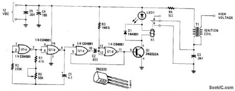

In essence, the circuit is nothing more than an auto ignition coil and a set of points which accomplishes the same thing. A pulsing circuit made from a single CMOS NOR integrated circuit (U1), opens and closes the relay contacts to simulate the action of the original breaker points. The relay pulser is divided into two clocking functions. The first circuit is a free-running squarewave generator that determines the rate or frequency of the pulses that activate the relay. It is essentially a pair of NOR gates connected as inverters and placed in a feedback loop, they are U1-b. The oscillating period of the feedback loop is determined by timing components C1, R1, and variable resistor R5. (View)
View full Circuit Diagram | Comments | Reading(1549)
Single_cell_meter_amplifier
Published:2009/7/24 3:01:00 Author:Jessie
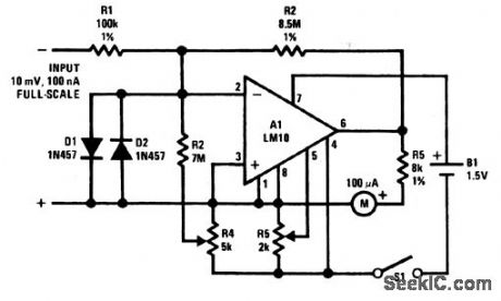
Accuracy for this meter amplifier can be maintained over a 15°C to 55°C range for a full-scale sensitivity of 10 mV to 100 mA. Offset-voltage error is nulled with R5, and bias current is balanced out with R4. Both offset and bias are operated from the reference, and are generally unaffected by changes in battery voltage, so frequency adjustments should not be necessary. Total current drain is under 0.5 mA, giving an approximate life of 3 to 6 months with an AA cell, or over one year with a D cell. (View)
View full Circuit Diagram | Comments | Reading(655)
Single_cell_electronic_thermometer
Published:2009/7/24 3:04:00 Author:Jessie
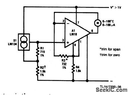
This circuit is useful in the range from -55°C to 150°C. Sensor S1 develops a current that is proportional to absolute temperature so that the readout could be in °F, rather than in °C, by trimming R2 and R3. With the values shown, readout is from 0° to 100°C. Refer to chapter 13 for information on temperature scales and absolute temperature. (View)
View full Circuit Diagram | Comments | Reading(711)
Portable_light_level_meter_with_five_decade_dynamic_range
Published:2009/7/24 3:02:00 Author:Jessie
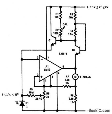
This circuit operates from a single cell and is calibrated at midrange with appropriate illumination by adjusting R2 so that output equals the reference, and the meter is 'at center scale. In practical terms, adjust R6 and R2 so the output meter follows a standard light meter. Note that the log slope is not temperature compensated, so there might be error at the scale extremes. Also, silicon photodiodes (D1) are sensitive to near-infrared light, but ordinary film is not. So, an infrared-stop filter is recommended. A blue-enhanced photodiode for D1 or an appropriate correction filter will also produce excellent results. (View)
View full Circuit Diagram | Comments | Reading(679)
12_V_preset_output_high_efficiency_controller_boot_strapped
Published:2009/7/24 3:12:00 Author:Jessie
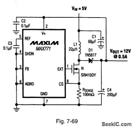
Figure 7-69 shows a MAX771 connected to provide 12-V output at 0.5 A, with a 5-V input.See Fig.7-68 for component suppliers. MAXIM NEW RELEASES DATA Book 1995, P.4-150. (View)
View full Circuit Diagram | Comments | Reading(676)
Single_cell_noninverting_20_dB_amplifier
Published:2009/7/24 3:12:00 Author:Jessie
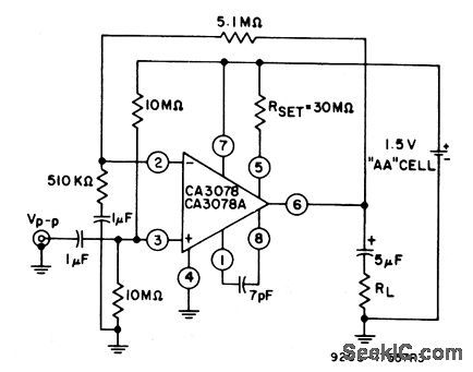
This circuit is identical to that of Fig. 8-33, except that the output is noninverting. (View)
View full Circuit Diagram | Comments | Reading(676)
Single_cell_inverting_20_dB_amplifier
Published:2009/7/24 3:11:00 Author:Jessie
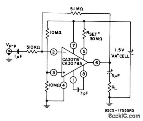
Total power consumption for this circuit is about 675 nA. The output voltage swing is 300 mVPP, with a 20-kΩ load. (View)
View full Circuit Diagram | Comments | Reading(725)
5_V_prese_output-efficiency_controller
Published:2009/7/24 3:11:00 Author:Jessie
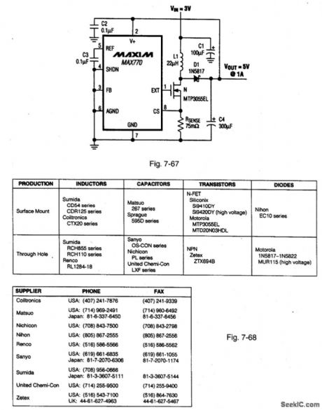
Figure 7-67 shows a MAX770 connected to provide 5-V output at 1 A with a 3-Vinput Figure 7-68 shows component suppliers. MAXIM NEW RELEASES DATA Book 1995 P. 4-150.4-149. (View)
View full Circuit Diagram | Comments | Reading(691)
OFF_LINE_24_V_100_W_DC_SUPPLY_
Published:2009/7/24 3:48:00 Author:Jessie
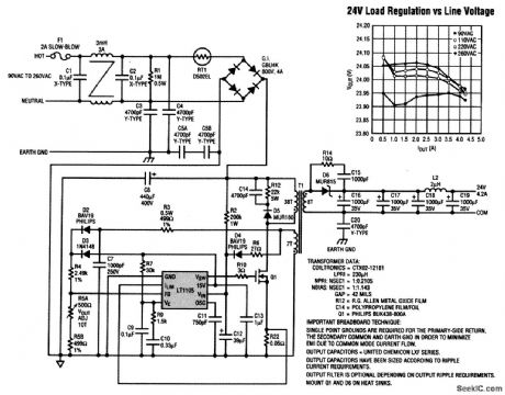
Today's electronic systems often rely on distributed power to support a myriad of control functions. This contrasts with historical approaches, which provided a regulated dc voltage to each of the subsystems with an off-line converter, often an expensive off-the-shelf box with less-than-optimal reliability. Shown here is a discrete approach that simplifies the task of distributed power design, saving time and money during system design. The LT1105 current-mode PWM control IC makes a simple, low-cost, yet highly reliable distributed power supply with the added advantage of a customizable footprint. The 24-V output is regulated to better than ±1 percent over a line range of 90 to 260 Vac and an 8:1 dynamic load range. A maximum output current of 4.2 A is available for a total of 100 W. All components, including the transformer, are specified in this design. The trans-former meets international safety standards UL 1950 and IEC950. This transformer and others that provide 36 or 48 V at 100 W are available off the shelf. The LT1105 uses unique design techniques, eliminating the optocoupler feedback normally found in off-line supplies, yet enabling the regulator to provide tight line and load regulation. A totem-pole output drives the gate of an external high-voltage FET (Q1), and switch current is monitored by sense resistor R22. Short-circuit protection is provided by burp mode operation, whereby the LT1105 will continuously shut down and restart during the fault condition. (View)
View full Circuit Diagram | Comments | Reading(1616)
Micropower_high_input_impedance_amplifier
Published:2009/7/24 3:22:00 Author:Jessie
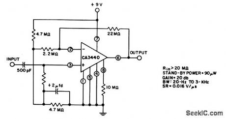
As shown by the table, standby power is 90 μW, with a 20-MΩ input impedance. (View)
View full Circuit Diagram | Comments | Reading(744)
24_V_preset_output_controller
Published:2009/7/24 3:22:00 Author:Jessie
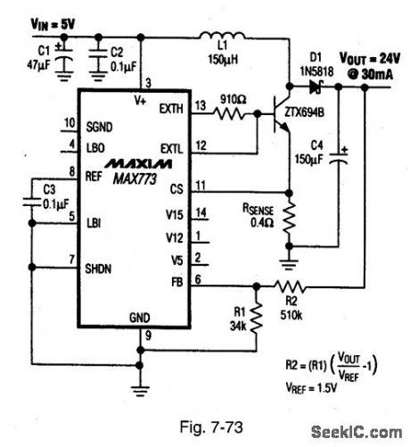
Figure 7-73 shows a MAX773 connected to provide 24-V output at 30 mA, with a 5-V input. See Fig. 7-69 for component suppliers. MAXIM NEW RELEASES DATA Book, 1995, P. 4-151. (View)
View full Circuit Diagram | Comments | Reading(696)
_5_V_low_dropout_voltage_regulator
Published:2009/7/24 3:43:00 Author:Jessie
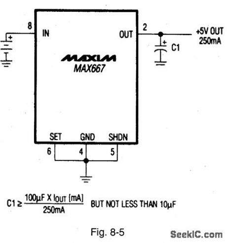
Figure 8-5 shows a MAX667 connected to provide a fixed +5-V output with minimum components and an input from +3.5 V to +16.5 V. Normal-mode quiescent current is a typica 120 μA, with 0.2-μA shutdown quiescent. MAXIM NEW RELEASES DATA Book, 1992, P. 4-137.
(View)
View full Circuit Diagram | Comments | Reading(662)
| Pages:149/291 At 20141142143144145146147148149150151152153154155156157158159160Under 20 |
Circuit Categories
power supply circuit
Amplifier Circuit
Basic Circuit
LED and Light Circuit
Sensor Circuit
Signal Processing
Electrical Equipment Circuit
Control Circuit
Remote Control Circuit
A/D-D/A Converter Circuit
Audio Circuit
Measuring and Test Circuit
Communication Circuit
Computer-Related Circuit
555 Circuit
Automotive Circuit
Repairing Circuit