
Index 145
Square_root_V_F_converter
Published:2009/7/24 1:39:00 Author:Jessie
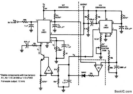
Fig, 12-27 This circuit generates an output frequency proportional to the square root of the input voltage. IC1 serves as a divider and V/F converter. The IC1 output goes back to the denominator input through IC2 (connected as a F/V converter) to make the circuit output equal to the input square root. The 5-kΩ scale-factor trim is adjusted for a full-scale output of 10 kHz. National Semiconductor Linear Applications Handbook 1991 p 1309. (View)
View full Circuit Diagram | Comments | Reading(627)
PULSE_PEAK_METER
Published:2009/7/24 1:39:00 Author:Jessie
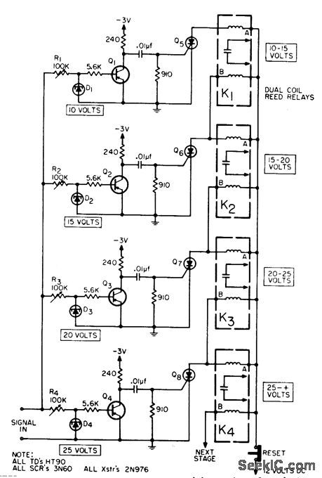
Indicates peak of fast voltage pulse to within one of several pre determined voltage ranges established by tunnel-diode level-sensing circuit and indicated by series of exclusive-or dual-coil reed relays.-J. C. Rich, Pulse-Peak Indicator, EEE,13:2, p 61. (View)
View full Circuit Diagram | Comments | Reading(647)
BRIDGE_BALANCER
Published:2009/7/24 1:38:00 Author:Jessie
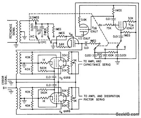
Reference signal from capacitance bridge is transformer-coupled into phase-shifting circuit to compensate for phase shifts in bridge and amplifier used for automatic measurement of dielectric proper ties. Sheet beam tubes V3 and V4 provide gating action for rebalancing servos.-P. G. Frischmann, Measuring Dielectric Properties Automatically, Electronics, 33:32, p 56-57. (View)
View full Circuit Diagram | Comments | Reading(667)
Product_V_F_convertermultiplier
Published:2009/7/24 1:37:00 Author:Jessie
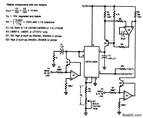
Fig.2-26 This circuit converts the product of two voltages to an equivalent frequency. The 5-kΩ scale-factor trim is adjusted so that the frequency output equals the ratio of V1/V2, as shown by the equations. (View)
View full Circuit Diagram | Comments | Reading(634)
POWER_FREQUENCY_HARMONIC_METER
Published:2009/7/24 1:37:00 Author:Jessie
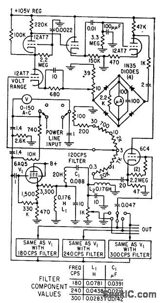
Has four bandpass filters, tuned to first four harmonics of 60 cps, and vtvm that measures voltage at each filter output, in five ranges covering from 0.3 to 30 v full scale.-. S. Brown, Tuned Voltmeter Reads Harmonic Amplitude, Electronics, 32:3, p 68. (View)
View full Circuit Diagram | Comments | Reading(678)
Regulator_with_output_shutdown_on_dropout_battery_low
Published:2009/7/24 2:28:00 Author:Jessie
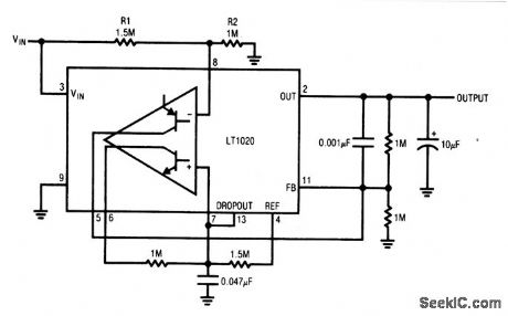
With this circuit, power is turned completely off when dropout begins (battery low). The circuit will not turn on until (VIN×R2)/( R1+ R2)=2.5 V. This prevents battery creep back from causing oscillation. In some cases, battery voltage will rise temporarily after going low. (View)
View full Circuit Diagram | Comments | Reading(615)
_48_V_input_to_5_V_output_zoithout_transformer
Published:2009/7/24 2:28:00 Author:Jessie
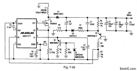
Figure 7-56 shows the MAX1771 connected to provide a 5-V output at 300 mA, with a -48-V input. No transformer is required. The conversion efficiency is typically 82%. See Fig. 7-51 for component suppliers. MAXIM NEW RELEASES DATA Book, 1995, P. 4-27. (View)
View full Circuit Diagram | Comments | Reading(799)
12-V_high-efficiency_controller_boot-strapped
Published:2009/7/24 2:09:00 Author:Jessie
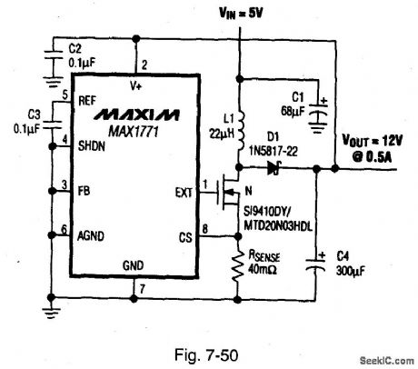
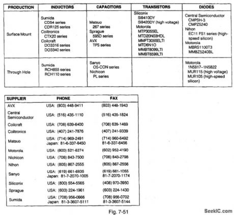
Figure 7-50 shows a MAX1771 connected to provide 12-V output at 0.5 A. vith a 5-V input. Figure 7-51 shows component suppliers. MAXIM NEW RELEASES DATABook. 1995 P.4-20.
(View)
View full Circuit Diagram | Comments | Reading(761)
SELF_INDICATING_REGISTER
Published:2009/7/24 1:52:00 Author:Jessie
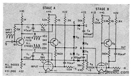
Combines two self-indicating flip-flops with phase splitter that converts single-polarity shift pulses to positive and negative-going pulses for all stages. Indicator triodes are Amperex 6977.-H. Rodriques de Miranda and I. Rudich, Indicator Triode for Direct Data Readout, Electronics, 33:6, p 52-54. (View)
View full Circuit Diagram | Comments | Reading(623)
Basic_F_V_converter_1
Published:2009/7/24 1:51:00 Author:Jessie
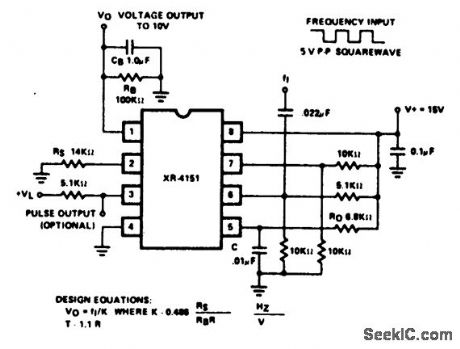
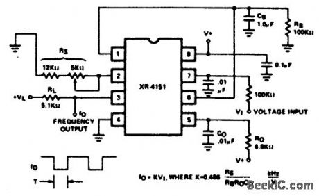
Fig. 12-33 This circuit uses an XR4151 and a few external components to form a basic F/V converter. Using the values shown, the input frequency is from 0 to 10 kHz, and output voltage is from 0 to 10 V. It might be necessary to square up the input signals. Also, the values for the input differentiator can be altered to accommodate square-wave inputs of different amplitudes and frequencies. EXAR Corporation Databook, 1990.p. 5 124. (View)
View full Circuit Diagram | Comments | Reading(1944)
1_PPS_CLOCK_GENERATOR
Published:2009/7/24 1:51:00 Author:Jessie
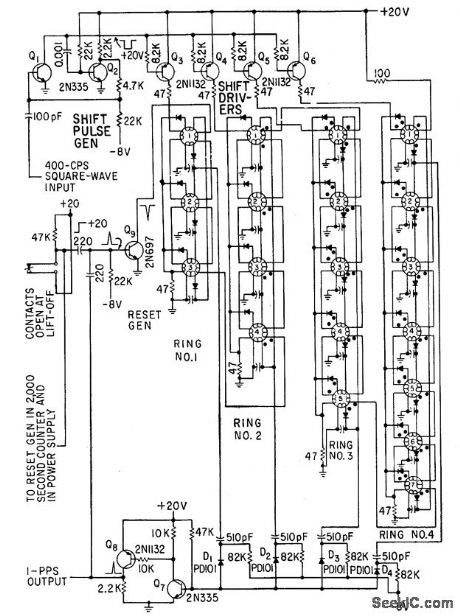
Uses unique magnetic shift register in which elements are connected in rings, with output of first element connected to input of first. Each ring has own driver, all operated from same 400-cps pulse generator.-J. H. Porter, Miniaturized Autopilot System for Missiles, Electronics, 33:43, p 60-64. (View)
View full Circuit Diagram | Comments | Reading(1321)
Precision_V_F_converter
Published:2009/7/24 1:50:00 Author:Jessie
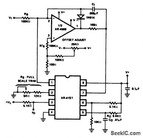
Fig. 12-32 This circuit is similar to that of Fig. 12-31, except that the additional op amp permits the circuit to retain linearity over the full range of input voltage, all the way to 0 V. Trim the full-scale adjust pot so that a 10-V input produces a 10-kHz output. Then, set the offset-adjust pot for 10 Hz with an input of 10 mV. EXAR Corporation Databook, 1990, p 5-124 (View)
View full Circuit Diagram | Comments | Reading(764)
SIMPLE_FET_VOLTMETERS
Published:2009/7/24 1:50:00 Author:Jessie
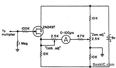
Uses single active device to indicate full scale at 1 v input, for sensitivity of 1 meg per volt. Bias is at 300 microamp drain current, approximately point of zero drift.-L. J. Sevin, Jr., Field-Effect Transistors, McGraw-Hill, N.Y., 1965, p 109. (View)
View full Circuit Diagram | Comments | Reading(705)
2000_SEC_COUNTER
Published:2009/7/24 1:50:00 Author:Jessie
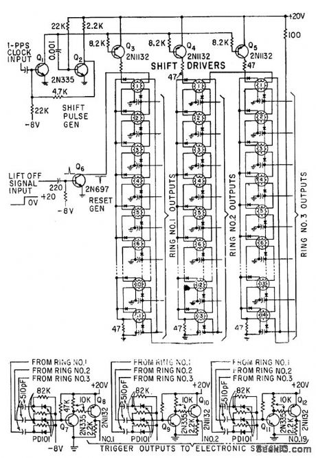
Up to 20 and gate in-puts can be supplied by each closed ring element. 1-pps clock triggers operate 2,000-sec counter pulse generator using unique magnetic shift register elements.-J. H. Porter, Miniaturized Autopilot System for Missiles, Electronics, 33:43, p 60-64. (View)
View full Circuit Diagram | Comments | Reading(601)
PRECISION_A_C_VOLTMETER
Published:2009/7/24 1:49:00 Author:Jessie
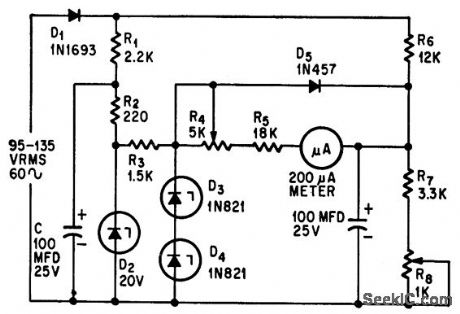
Measures a-c voltages between 95 and 135 v with 0.6% accuracy while using ordinary 2% accuracy meter. Zener diodes provide reference voltage.-D. S. Belanger, Simple Circuit Increases Measurement Accuracy, Electronics, 38:22, p 69. (View)
View full Circuit Diagram | Comments | Reading(685)
Basic_V_F_converter
Published:2009/7/24 1:48:00 Author:Jessie
Pig. 12-31 This circuit uses an XR4151 and a few external components to form a basic V/F converter. Using the values shown, input voltage is from 0 to + 10V, and output frequency is from 0 to 10 kHz. Full-scale frequency is trimmed by RS. EXAR Corporation Databook 1990 p 5-123.
(View)
View full Circuit Diagram | Comments | Reading(2437)
Step_down_P_channel_controllers
Published:2009/7/24 1:48:00 Author:Jessie
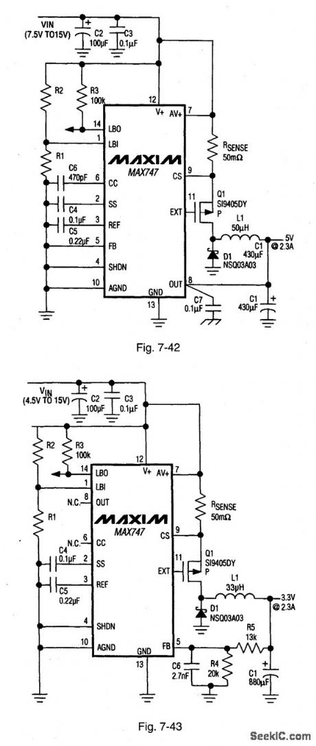
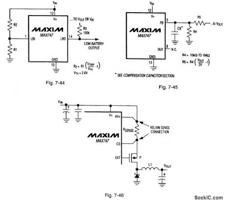
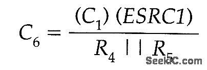
Figure 7-42 shows the MAX747 connected to provide +5 V at 2.3 A with a 7.5-V to 15-V input. Figure 7-43 shows the MAX747 connected to provide +3.3 V at 2.3 A with a 4.5-V to 15-V input. Figure 7-44 shows the calculations required for the low-battery detector circuit. LBO goes low when V+ is equal to or less than VTRIP. LBO is high impedance in the shutdown mode. Figure 7-45 shows the calculations required to adjust the output from 2 V to 14 V. The value of C6 is calculated using:where C1 is the value of C1 in μF, and ESRC1 (effective series resistance of C1 at 100 kHz) is in ohms. Figure 7-46 shows the recommended Kelvin connections for the current-sense resistor. MAXIM NEW RELEASES DATA Book, 1994, P. 4-140, 4-143, 4-145.
(View)
View full Circuit Diagram | Comments | Reading(732)
Micropower_V_F_converter_1_MHz
Published:2009/7/24 1:47:00 Author:Jessie
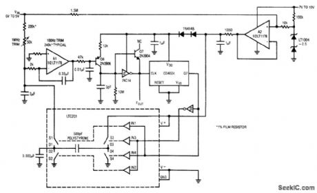
Fig. 12-30 In this circuit, a 0- to 5-V input produces a 100-Hz to 1-MHz output with a linearity of 0.02%. Drift is about 50 ppm/℃. Maximum current consumption (at 1 MHz) is about 360μA. To trim, apply 500μV and select a value (typically 240 kΩ) at the A1noninverting input for a 100-Hz output. Then, apply 5 V and adjust the 50-kΩ trim for a 1-MHz output. Then, apply 5 V and adjust the 50-kΩ trim for a 1-MHz output. Linear Technology. Linear Applications Handbook 1990 p AN23-13. (View)
View full Circuit Diagram | Comments | Reading(742)
FET_D_C_MILLIVOLTMETER_1
Published:2009/7/24 1:47:00 Author:Jessie
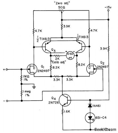
Consists of two circuits much like bootstrapped source-follower, differentially connected and fed by active current source. Input of 50 my produces full-scale defection, making sensitivity 20 meg/v.-L. J. Sevin, Jr., Field-Effect Transistors, McGraw-Hill, N.Y., 1965, p 110. (View)
View full Circuit Diagram | Comments | Reading(729)
Single_cell_voltage_up_converter
Published:2009/7/24 1:46:00 Author:Jessie
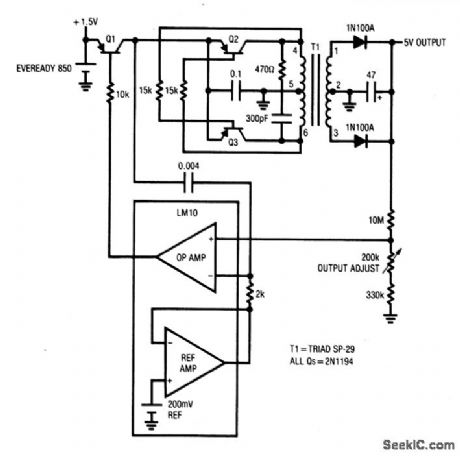
This circuit will supply a 5-V 150-μA load (about 25 CMOS SSI ICs, for example) for 3000 hours from a single 1.5-V D-cell battery. (View)
View full Circuit Diagram | Comments | Reading(625)
| Pages:145/291 At 20141142143144145146147148149150151152153154155156157158159160Under 20 |
Circuit Categories
power supply circuit
Amplifier Circuit
Basic Circuit
LED and Light Circuit
Sensor Circuit
Signal Processing
Electrical Equipment Circuit
Control Circuit
Remote Control Circuit
A/D-D/A Converter Circuit
Audio Circuit
Measuring and Test Circuit
Communication Circuit
Computer-Related Circuit
555 Circuit
Automotive Circuit
Repairing Circuit