
power supply circuit
Index 160
Dc_stabilization_using_differential_sensing
Published:2009/7/24 20:44:00 Author:Jessie
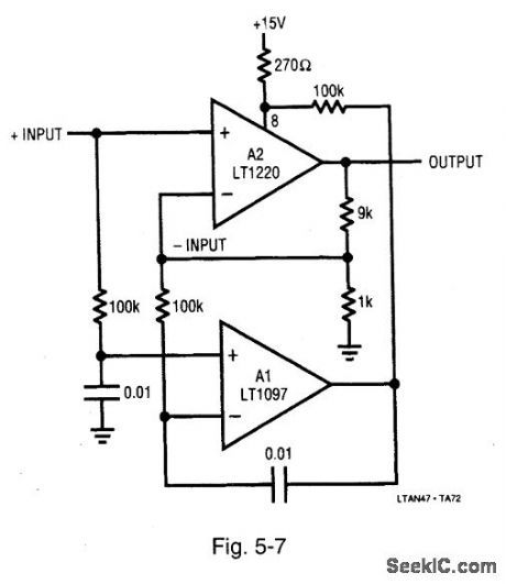
Figure 5-7 is similar to Fig. 5-6, except that the sensing is done differentially, preserving access to both fast amplifier inputs. The combined characteristics of these amplifiers yields the following performance: 50-μV offset voltage, 1-μV/℃ offset drift, 250-V/μs slew rate, and 45-MHz gain bandwidth. LINEAR TECHNOLOGY, APPLICATION NOTE 47, P. 34. (View)
View full Circuit Diagram | Comments | Reading(694)
Wideband_fast_settling_op_amp_with_multplex_input
Published:2009/7/24 21:45:00 Author:Jessie
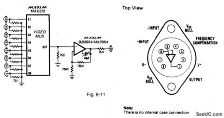
Figure 6-11 shows a BB3554/MX3554 used with a MAX310 to provide eight channels of video signal to a single cable. The op amp slews at 1000 V/μs and provides up to ±100 mA output with±10-V supplies. MAXIM NEW RELEASES DATA BOOK, 1993, P. 3-43. (View)
View full Circuit Diagram | Comments | Reading(709)
Ultra_fast_ECL_output_comparator
Published:2009/7/24 21:43:00 Author:Jessie
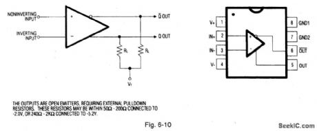
Figure 6-10 is similar to Fig. 6-9, but without the latch-enable function. Propagation delay is 1.3 ns. MAXIM NEW RELEASES DATA BOOK, 1993, P. 3-41. (View)
View full Circuit Diagram | Comments | Reading(731)
Ultra_fast_ECL_output_comparator_with_latch_enable
Published:2009/7/24 21:42:00 Author:Jessie
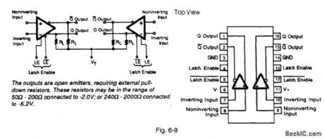


Figure 6-9 shows a MAX9687 connected as a fast (600 MHz) output comparator under latch control. The latch-enable inputs can be driven from a standard ECL gate. When LE is high and LE is low, the comparator function is normal. When LE is low and LE is high, the comparator outputs are locked in the logic states determined by the input conditions at the time of the latch transition. If the latch-enable function is not used, connect LE to ground and leave LE open. The propagation delay is 1.4 ns, the latch setup time is 0.5 ns, the latch-enable pulse width is 2.0 ns, and the power supplies are +5 V and -5.2 V. MAXIM NEW RELEASES DATA BOOK, 1993, P. 3-39. (View)
View full Circuit Diagram | Comments | Reading(1190)
GELLED_ELECTROLYTE_BATTERIES
Published:2009/6/29 23:05:00 Author:May
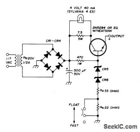
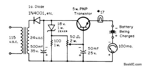
Constant-voltage charger for Globe-Union 12-V gelled-electrolyte storage batteries can provide either fast or float charging. Constant voltage is maintained by series power transistor and series-connected zeners. Output voltage is 13.8 V for float charging and 14.4 V for fast charging.-E. Noll, Storage-Battery QRP Power, Ham Radio, Oct. 1974, p 56-61. (View)
View full Circuit Diagram | Comments | Reading(2447)
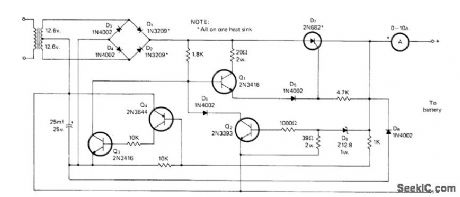
12_V_FOR_GELLED_ELECTROLYTE
Published:2009/6/29 23:02:00 Author:May
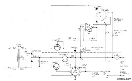
Designed to charge 12-V 3-Ah gelled-electrolyte battery such as Elpower EP1230A at maximum of 0.45 A until battery reaches 14 V, then at constant voltage until charge current drops to 0.04 A. Charger is then automatically switched to float status that maintains 2.2 V per cell or 13.2 V for battery. Circuit is constant-voltage regulator with current limiting as designed around National LM305H, with PNP/NPN transistor pair to increase current capability. Circuit above dashed line is added to standard regulator to meet special charging requirement. Article covers operation and use of circuit in detail.-H.Olson, Battery Chargers Exposed, 73 Magazine Nov.1976, p 98-100 and 102-104. (View)
View full Circuit Diagram | Comments | Reading(868)
SOLAR_ENERGY_CHARGER
Published:2009/6/29 23:00:00 Author:May
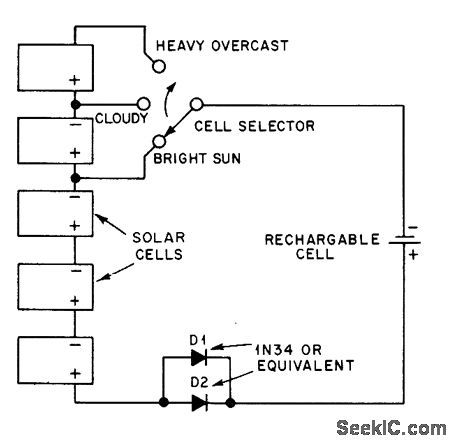
Single solar cell on bright day delivers 0.5 V at 50 mA, so three cells are used in bright sun to recharge secondary cell. Switch permits use of additional solar cells on cloudy days. Solar cells can be Radio Shack 276-128.-J. Rice, Charging Batteries with Solar Energy, OST, Sept. 1978, p 37. (View)
View full Circuit Diagram | Comments | Reading(1260)
NICAD_CHARGER_3
Published:2009/6/29 22:59:00 Author:May
Regulated charger circuit will handle variable load from 1 to 18 nicad cells. Current-limiting action holds charging current within 1 to 2 mA of optimum value (about one-tenth of rated ampere-hour capacity) from 0 to 24 V. Q1 should have power rating equal to twice supply voltage mu ltiplied by current-limit value, lf charging 450-mAh penlight cells, charge current is 45 mA and transistor should be 2W.-A. G. Evans, Regulated Nicad Charger, 73 Magazine, June 1977, p 117. (View)
View full Circuit Diagram | Comments | Reading(1027)
CONSTANT_CURRENT_NICAD_CHARGER
Published:2009/6/29 22:56:00 Author:May
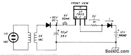
Constant current is obtained from voltage regulator by floating common line and connecting R1 from output to common terminal, Regulator then tries to furnish fixed voltage across R1. Input voltage must be greater than full-charge battery voltage plus 5 V (for 5-V regulator) plus 2 V (overhead voltage). Changing R1 varies charging curent. If R1 is 50 ohms and V is 5 V, constant current is 50 mA through nicad being charged.-G. Hinkle, Constant-Current Battery Charger for Portable Operation, Ham Radio, April 1978, p 34-36. (View)
View full Circuit Diagram | Comments | Reading(808)
FLASHING_LED_FOR_LOW_BATTERY
Published:2009/6/29 22:54:00 Author:May
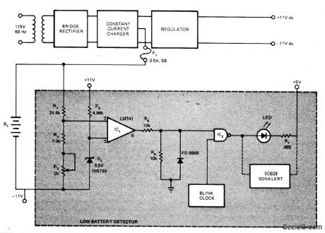
Developed for use in portable battery-operated test instrument to provide visual indication that depletion level has been reached for series arrangement of 24 nickel-cadmium cells providing 32.5 VDC for regulator of bipolar 11-V supply. Instrument must then be plugged into AC line for recharging of batteries. Voltage across B1 (nominally 32.5 V) is sensed by R1-R4 and D1. When level drops 24.1 V, opamp comparator output goes positive and enables gate IC2, so blink clock (such as low-frequency TTL-Level oscillator) makes LED flash. Audible alarm is optional.-R. T. Wamer, Monitor NiCad's with This Low-Battery Detector, EDN Magazine, April 20, 1976, p 112 and 114. (View)
View full Circuit Diagram | Comments | Reading(958)
UJT_CHARGER_FOR_12_V
Published:2009/6/29 22:46:00 Author:May
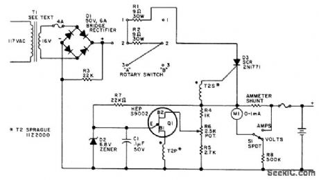
Keeps 12-V auto storage battery fully charged, for immediate standby use when AC power fails. Power trans-former secondary can be 14 to 24 V, rated at about 3 A. Two-gang rotary switch gives choice of three charging rates. Pulse transformer 72 is small audio transformer rewound to have 1:1 turns ratio and about 20 ohms resistance, or can be regular SCR trigger transformer. UJT relaxation oscillator stops when upper voltage limit for battery is reached, as set by pot R6. If oscillator fails to start, reverse one of pulse trans-former windings.-F. J. Piraino, Failsafe Super Charger, 73 Magazine, Holiday issue 1976, p 49. (View)
View full Circuit Diagram | Comments | Reading(741)
12_V_CHARGER
Published:2009/6/29 22:45:00 Author:May
Heath GP-21 charger uses SCR as switch to connect and disconnect battery at 120-Hz rate. Voltage at anode of SCR D7 goes positive each half-cycle, putting forward bias on base of Q1 through 1.8K resistor so Q1 passes current through D5 to gate of D7 to turn it on for part of half-cycle and charge battery. D7 stays on until voltage across it drops to zero. When battery has eharged to 13.4 V, charging stops automatically. Rest of circuit protects against battery polarity reversal and accidental shorting of output leads. Special 12.8-V zener can be replaced by selected 1N4742 and forward-biased 1N4002.-H. Olson, We Don't Charge Nothin' but Batteriesl, CQ, Feb. 1976, p 25-28 and 69. (View)
View full Circuit Diagram | Comments | Reading(1336)
NICAD_CHARGER_2
Published:2009/6/29 22:43:00 Author:May
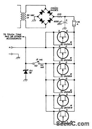
Developed for recharging small nickel-cadmium batteries used in handheld FM transceivers. Field-effect transistors serve as constant-current sources when gate is shorted to source. Practically any N-channel JFET having drain-to-source cument of 8-15 mA will work. FETs shown were measured individually and grouped to give desired choice of 15- or 50-mA charging currents.-G. K Shubert, FET-Controlled Charger for Small Nicad Batteries, Ham Radio, Aug. 1975, p 46-47. (View)
View full Circuit Diagram | Comments | Reading(762)
NICAD_CHARGER_1
Published:2009/6/29 22:42:00 Author:May
Pot is adjusted to provide 10% above rated voltage (normal full-charge voltage) while keeping charging current below 25% of maximum,For 10-V 1-Ah battery,set voltage at 11 V and current below 250 mA.-G.E.Zook, F.M., CQ,Feb. 1973, p 35-37. (View)
View full Circuit Diagram | Comments | Reading(664)
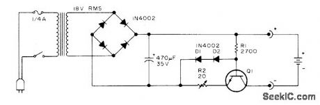
BASIC_12_V_CHARGER
Published:2009/6/29 22:05:00 Author:May

Uses 200-W lamp as current-limiting resistor in transformer primary circuit. Serves in place of older types of chargers using copper-oxide or tungar-bulb rectifiers.-H.Olson, Battery Chargers Exposed, 73 Magazine, Nov.1976, p 98-100 and 102-104. (View)
View full Circuit Diagram | Comments | Reading(1294)
SOLAR_POWER_OVERCHARGE_PROTECTION
Published:2009/6/29 22:02:00 Author:May
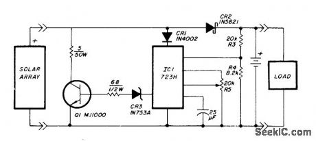
Voltage regulator is connected across solar-cell away as shown to prevent damage to storage battery by overcharging. Series diode prevents array from discharging battery during hours of darkness. Regulator does not draw power from battery, except for very low current used for voltage sampling. Battery can be lead-calcium, gelled-electrolyte, or telephone-type wet cells, For repeater application described, two Globe Union GC12200 40-Ah gelled-electrolyte batteries were used to provide transmit current of 1.07 A and idle current of 12 mA.-T. Handel and P. Beauchamp, Solar-Powered Repeater Design, Ham Radio, Dec. 1978, p 28-33. (View)
View full Circuit Diagram | Comments | Reading(3070)
Power_booster
Published:2009/7/24 21:08:00 Author:Jessie
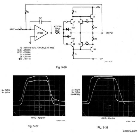
Figure 5-36 shows a 200-mA power booster used with an LT1220 amplifier. Figure 5-37 shows booster performance with the LT1220 removed. The input pulse (trace A) is applied to the booster input, with the output (trace B) taken at the indicated point. The total delay is about 1 ns. Figure 5-38 shows pulse response with the LT1220 installed and a 50-Ω load. The input (trace A) produces a slew-limited output (trace B). LINEAR TECHNOLOGY, APPLICATION NOTE 47, P. 46. (View)
View full Circuit Diagram | Comments | Reading(1)
Cable_driver_with_minimum_phase_distortion
Published:2009/7/24 21:36:00 Author:Jessie
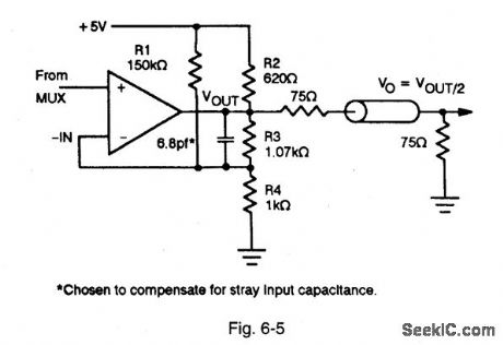
Figure 6-5 shows how the circuits of Figs. 6-3 and 6-4 can be connected to provide minimum phase distortion. MAXIM NEW RELEASES DATA Book, 1993, P. 3-20. (View)
View full Circuit Diagram | Comments | Reading(739)
Op_amp_Wien_bridge_sine_wave_oscillator
Published:2009/7/24 21:35:00 Author:Jessie
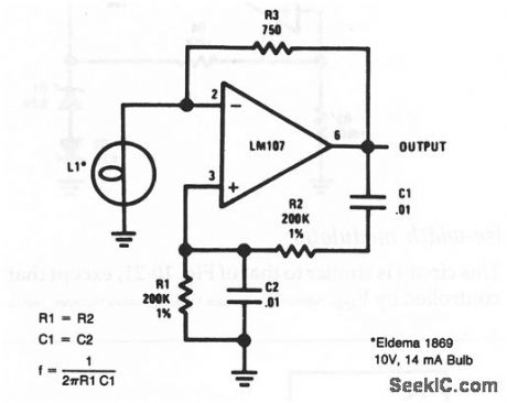
This drcuit is the op-amp version of the dassic Wien-bridge oscillator (chapter 5) using the negative-resistance characteristics of a lamp to stabilize operation. (View)
View full Circuit Diagram | Comments | Reading(1119)
Threshold_detector_for_rphotodiodes
Published:2009/7/24 21:31:00 Author:Jessie
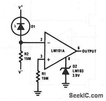
This circuit converts small input currents produced by D1 into levels suitable to drive DTL/TTL loads. Different values of R1/R2 can be selected to set different on/off levels. (View)
View full Circuit Diagram | Comments | Reading(650)
| Pages:160/291 At 20141142143144145146147148149150151152153154155156157158159160Under 20 |
Circuit Categories
power supply circuit
Amplifier Circuit
Basic Circuit
LED and Light Circuit
Sensor Circuit
Signal Processing
Electrical Equipment Circuit
Control Circuit
Remote Control Circuit
A/D-D/A Converter Circuit
Audio Circuit
Measuring and Test Circuit
Communication Circuit
Computer-Related Circuit
555 Circuit
Automotive Circuit
Repairing Circuit