
power supply circuit
Index 146
POWER_ON_RESET
Published:2009/7/2 20:13:00 Author:May
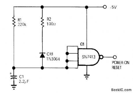
One Schmitt trigger and three discrete components ensure correct initial state of logic circuits when power is applied.During charge time of C1, output of gate G1 is high. When C1 reaches 1.5V, gate output goes low and terminates power-on reset.-R. C. Snyder, Single-Voltage Circuit Generates Power-On Reset Pulse, EDNIEEE Magazine, Jan. 1, 1972, p 72. (View)
View full Circuit Diagram | Comments | Reading(0)
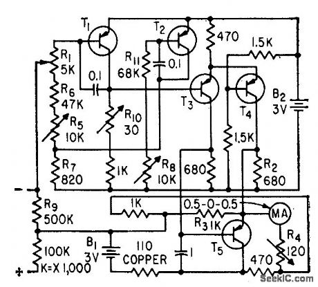
HYBRID_VIVM
Published:2009/7/24 2:00:00 Author:Jessie
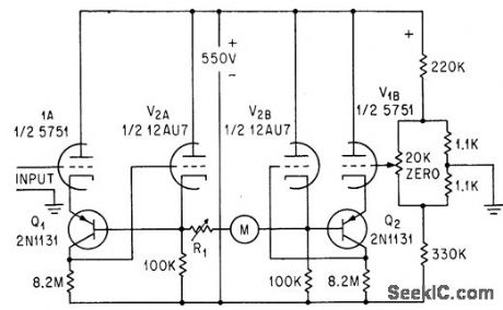
Transistor in each side of balanced vtvm reduces output impedance to fraction of ohm, making meter reading independent of aging of tubes.-J. J. Faran Jr., Hybrid Voltmeter Avoids Aging Errors, Electronics, 36:38, p 41. (View)
View full Circuit Diagram | Comments | Reading(963)
REGISTER_DRIVER
Published:2009/7/24 2:00:00 Author:Jessie
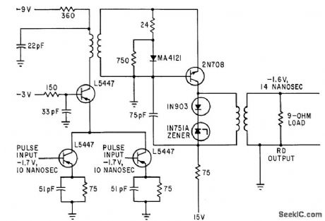
Handles 10-nsee pulses for 50-megapulse computer. Can drive eight 75-ohm lines.-K. H. Konkle and J. E. Laynor, Key to Faster Computers: Ten-Nanosecond Amplifier, Electronics, 35:50, p 39-41. (View)
View full Circuit Diagram | Comments | Reading(885)
Sine_wave_output_converter
Published:2009/7/24 1:59:00 Author:Jessie
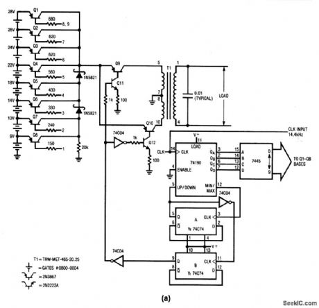
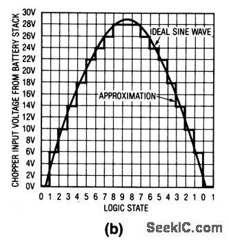
This circuit produces a sine-wave output by sequentially switching segments of a 28-V battery stack into a fixed gain, step-up voltage chopper, under digital control. The circuit requires a 14.4-kHz clock. Figure 8-12B shows the voltage presented to the chopper as a function of the sequencing. T1 receives the alternating drive and steps up the voltage. With the values shown, the output is 115 V, 400 Hz, with a power capability of about 20 W. (View)
View full Circuit Diagram | Comments | Reading(881)
DIFFERENTIAL_FET_VOLTMETER
Published:2009/7/24 1:59:00 Author:Jessie
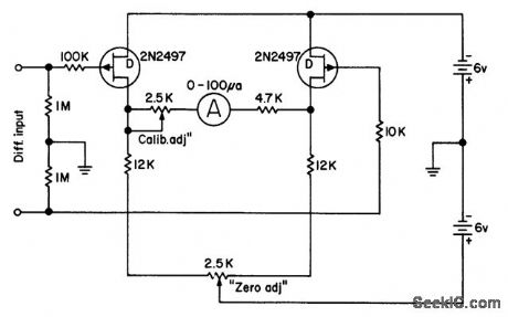
Two singleended circuits connected back to back give sensitivity of 1 meg/v-L.J. Sevin, Jr., Field-Effect Transistors, McGraw-Hill,N.Y.,1965,p 110. (View)
View full Circuit Diagram | Comments | Reading(866)
TUNNEL_DIODE_SHIFT_REGISTER
Published:2009/7/24 1:59:00 Author:Jessie
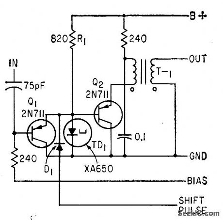
Incorporates tunnel-diode steering by Q1 and D1. T1 provides necessary phase reversal.-W. V.Harrison and R. S. Foote, Tunnel Diodes Increase Digital-Circuit Switching Speeds, Electronics, 34:32, p 154-156. (View)
View full Circuit Diagram | Comments | Reading(738)
PEAK_VOLTMETER
Published:2009/7/24 1:58:00 Author:Jessie
Auxiliary flip-flop compares input pulse with voltage already on integrating capacitor. Flip-flop then automatically adjusts capacitor charge to match peak voltage of input. Q2 is integrcaor, controlled by flip-flop Q1-Q2.-R. P. MacKenzie, Novel Design Peak Voltmeter, Electronics, 33:25, p 57. (View)
View full Circuit Diagram | Comments | Reading(955)
SHIFT_REGISTER_DRIVER
Published:2009/7/24 1:58:00 Author:Jessie
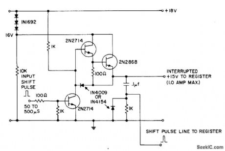
Shift pulse input saturates 2N2714, depriving Darlington combination of base drive. Resulting negative pulse generated on 15-V line is differentiated lo produce positive trigger pulse at its trailing edge.- Transistor Manual, Seventh Edition, General Electric Co., 1964, p 432. (View)
View full Circuit Diagram | Comments | Reading(2252)
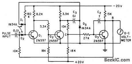
TRANSISTOR_VOLTMETER
Published:2009/7/24 1:57:00 Author:Jessie
Has input impedance of 1 megohm per volt. D-c amplifier provides gain of 100,000.-W. Mosinski, Transistor Voltmeter is Accurate, Linear, Electronics, 32;4, p 56-57. (View)
View full Circuit Diagram | Comments | Reading(2517)
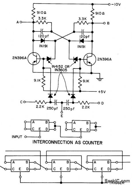
BASIC_BISTABLE_MODULE
Published:2009/7/24 1:57:00 Author:Jessie
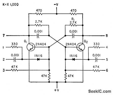
Can be used as flip-flop by connecting 1 to 7 and 4 to 8, than using 2 and 5 as inputs and 7 and 8 as outputs. Becomes binary counter stage when 2 and 5 are tied together for same arrangement. Other combinations of connections give one-shot mvbr, pulse generator, shift register, square-wave generator, or flip-flop.-A. I. Perlin, Selective Calling for Data Link Systems, Electronics, 33:18, p 108-110. (View)
View full Circuit Diagram | Comments | Reading(1124)
PEAK_VOLTAGE_MEMORY
Published:2009/7/24 1:57:00 Author:Jessie

When properly balanced, will measure voltages in range from 0 to 10 cps with average error of 0.5%. Used with conventional digital voltmeter. Stores low-frequency positive and negative peak-voltage excursions in memory capacitor whose linear charge characteristic is controlled by operational-amplifier limit circuit. Used for measuring low-frequency voltages in servo systems.-W. V. Weiss, Peak-Voltage Memory Measures Low. Frequency Voltages Accurately, EEE, 10:7, p 50-55. (View)
View full Circuit Diagram | Comments | Reading(1068)
BASIC_SHIFT_REGISTER_STAGE
Published:2009/7/24 1:56:00 Author:Jessie
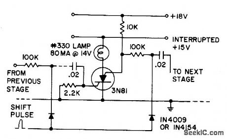
If silicon controlled switch stage is off, shift pulse (less than 15 V) will not be coupled to next stage. Anode supply is interrupted just before shift pulse, to turn off all stages. Stored capacitor charge then determines which stages will be retriggered.- Transistor Manual, Seventh Edition, General Electric Co., 1964, p 432. (View)
View full Circuit Diagram | Comments | Reading(841)
D_C_PREAMP_FOR_VTVM
Published:2009/7/24 1:55:00 Author:Jessie
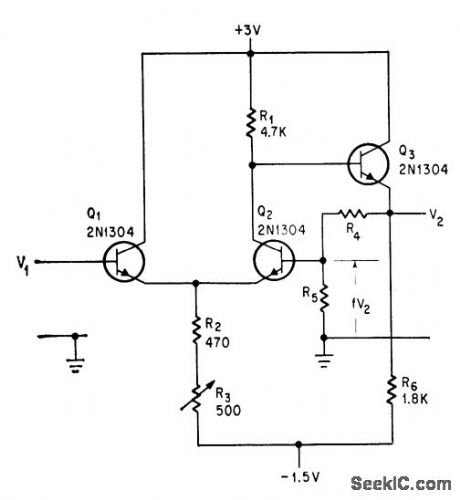
Prevents damage to transistors when making measurements with 1.5-v or 3-v range in semiconductor circuits. Feedback from Q3 to Q2 gives stability and linearity. Circuit can extend range of 1.5-v vtvm down to 500 or 150 mv full scale, but is sensitive to supply voltage variations and has open-circuit gain of only about 50.-A. K. Scidmore, Low-Cost Emitter-Follower Extends Voltmeter's Range, Electronics, 39:3, p 87. (View)
View full Circuit Diagram | Comments | Reading(812)
±15_V_converter
Published:2009/7/24 1:55:00 Author:Jessie
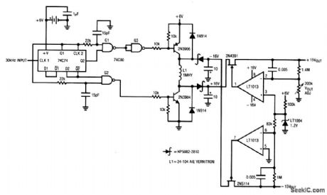
This circuit provides both +15-V and -15-V outputs at 30 mA, from a 6-V battery. However, a 30-kHz clock signal is required to drive a square-wave generator. (View)
View full Circuit Diagram | Comments | Reading(854)
5_A_steyo_down_PWM_regulator
Published:2009/7/24 1:55:00 Author:Jessie

Figure 7-47 shows the MAX787 connected to provide an output of +5 V at 5 A, with an input of 10 V to 40 V. The MAX787/88/89 provide 5-A outputs at 5 V, 3.3 V, and 3 V, respectively. Quiescent current is 8.5 mA. The ICs are also available in TO-3 packages. MAXIM NEW RELEASES DATA Book, 1994, P. 4-245. (View)
View full Circuit Diagram | Comments | Reading(713)
500_KC_SHIFT_REGISTER
Published:2009/7/24 1:54:00 Author:Jessie
Basic nonsaturated flip-flop, using 52-step design procedure given, serves as building block for 500-kc counter and shift register.- Transistor Manual, Seventh Edition, General Electric Co., 1964, p 190. (View)
View full Circuit Diagram | Comments | Reading(939)
Precision_F_V_converter
Published:2009/7/24 1:53:00 Author:Jessie
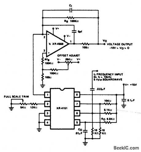
Fig. 12-34 This circuit is similar to that of Fig. 12-33, except that the additional op amp permits the circuit to retain linearity over the full range of input frequencies. Trim the full-scale adjust pot so that a 10-kHz input produces a -10-V output. Then, set the offset-adjust pot for a -10-mV output with an input of 10 Hz. EXAR Corporation Databook 1990 p 5-124. (View)
View full Circuit Diagram | Comments | Reading(1228)
100_V_A_C_REFERENCE
Published:2009/7/24 1:52:00 Author:Jessie
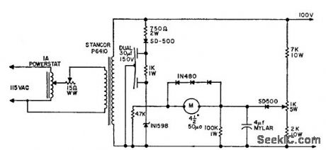
Accurate 100-v rms source is used as reference voltage for divider to correlate vacuum-tube voltmeters. Meter is altered to zero-center, with new settle scale indicaing voltages up to 1.825 v on each side of 100-v center value. D-c voltage on one side of meter is held constant by zener diode, and is compared with positive voltage applied to other meter terminal by divider action without stabilization. Initial standardization is done by adjusting input controls for 100-v output as determined by reference standard. Output potentiometer is then adjusted to make meter tor respond (center of scale). Three diodes protect meter when unit is turned on.-Standardized AC Voltage Reference Source, Electronic Circuit Design Handbook, Mactier Pub. Corp., N.Y., 1965, p 151. (View)
View full Circuit Diagram | Comments | Reading(798)
Regulated_15_V_converter
Published:2009/7/24 1:52:00 Author:Jessie
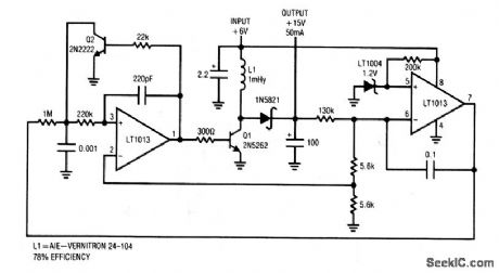
This circuit delivers a 15-V output to a 50 mA load from a 6-V battery. Efficiency is 78%. Regulation is within 0.05% over a wide range of output loads, with a typical temperature coefficient of 50 ppm/°C. (View)
View full Circuit Diagram | Comments | Reading(832)
VOLTAGE_DIP_COUNTER
Published:2009/7/24 2:04:00 Author:Jessie
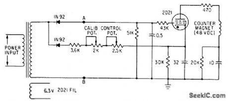
Each time a-c line voltage drops below adjustable threshold level, thyratron fires and operates electromagnetic counter. Used to count dips that might affect computer operation.-T. D. Koranye, Thyratron Monitors Line-Voltage Dips, Electronics, 34;1, p 126. (View)
View full Circuit Diagram | Comments | Reading(692)
| Pages:146/291 At 20141142143144145146147148149150151152153154155156157158159160Under 20 |
Circuit Categories
power supply circuit
Amplifier Circuit
Basic Circuit
LED and Light Circuit
Sensor Circuit
Signal Processing
Electrical Equipment Circuit
Control Circuit
Remote Control Circuit
A/D-D/A Converter Circuit
Audio Circuit
Measuring and Test Circuit
Communication Circuit
Computer-Related Circuit
555 Circuit
Automotive Circuit
Repairing Circuit