
Circuit Diagram
Index 1510
TEANA A33-EL Door Mirror Circuit One
Published:2011/7/15 2:27:00 Author:Joyce | Keyword: TEANA , Door Mirror
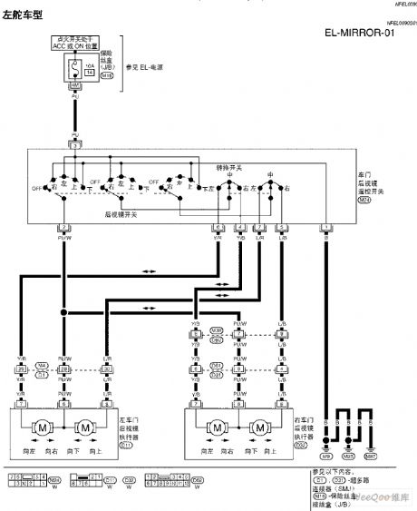
TEANA A33-EL Door Mirror Circuit (View)
View full Circuit Diagram | Comments | Reading(962)
TEANA A33-EL Trunk Lid and Refuel Coupling Door Circuit
Published:2011/7/15 2:34:00 Author:Joyce | Keyword: TEANA, Trunk Lid , Refuel Coupling Door
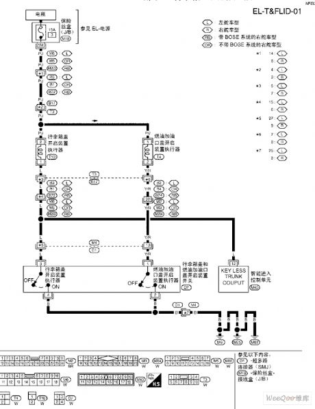
TEANA A33-EL Trunk Lid and Refuel Coupling Door Circuit (View)
View full Circuit Diagram | Comments | Reading(794)
Short Circuit or Input Back Protected Circuit Operating Only When Input Voltaged is Provided
Published:2011/7/19 2:04:00 Author:Joyce | Keyword: Short Circuit , Input Back , Protected, Input Voltaged , Provided
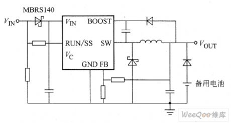
The circuit is protected from short circuit and input back. If the inductance value chosen will not be supersaturated, reducing voltage stabilizer LT3481 is able to withstand short cut of the output. But here’s another condition in the system to consider, that is when LT3481 has no input, the output will still maintain a high level. When the battery is charging or in battery backup systems, it may happen if the battery or any other power supply is connected with LT3481 by diode or (OR). If the end FIN is allowed to float, and end RUN / SS is connected with end VIN by a logic signal while keeping high level, the static current in internal circuit of LT3481 will be drawn through the end SW.
(View)
View full Circuit Diagram | Comments | Reading(541)
TEANA A33-EL Multifunctional Remote Control System Circuit Three
Published:2011/7/15 2:13:00 Author:Joyce | Keyword: TEANA , Multifunctional, Remote Control System
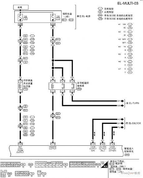
TEANA A33-EL Multifunctional Remote Control System Circuit (View)
View full Circuit Diagram | Comments | Reading(793)
TEANA A33-EL Multifunctional Remote Control System Circuit Four
Published:2011/7/15 2:14:00 Author:Joyce | Keyword: TEANA, Multifunctional , Remote Control System
TEANA A33-EL Multifunctional Remote Control System Circuit (View)
View full Circuit Diagram | Comments | Reading(762)
Operational Amplifier Used as SRS Effector Circuit
Published:2011/7/19 2:31:00 Author:Joyce | Keyword: Operational Amplifier, SRS Effector
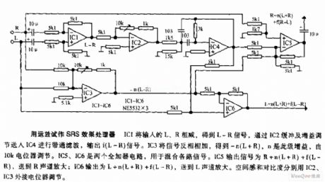
Operational Amplifier Used as SRS Effect Processor: R will be subtracted from L by IC1 to get a L-R signal. It will be sent into IC4 to be band-pass filtered to output f (L-R) signal after it is buffered and gain adjusted by IC2. IC3 will add the signal inversely to get -n(L+R), in which n is the gain in this stage regulated by 10k potentiometer. IC5 and IC6 are two full adder circuits, which are used to mix all kinds of signals. The output signal of IC5 is R+n(L+R)+f(L-R),which will be sent to track R to be amplified, and that of IC6 is L+n(L+R)+f(L-R),which will be sent to track L to be amplified. Extensity and contrast ratio will be regulated by potentiometer which will be connected externally by IC2 and IC3 respectively. (View)
View full Circuit Diagram | Comments | Reading(1376)
TEANA A33-EL NATS(Nissan Anti-theft System) Circuit
Published:2011/7/15 2:25:00 Author:Joyce | Keyword: TEANA , NATS
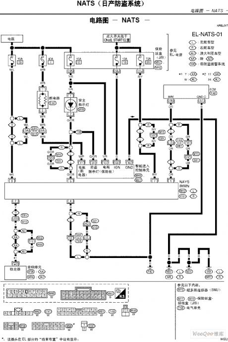
TEANA A33-EL NATS(Nissan Anti-theft System) Circuit (View)
View full Circuit Diagram | Comments | Reading(5039)
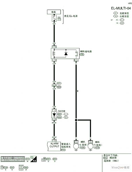
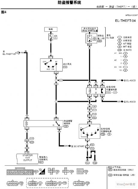
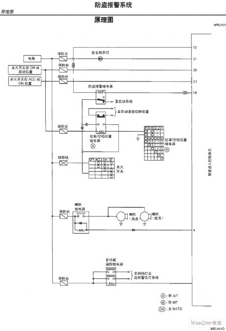
TEANA A33-EL Anti-theft Alarm System Circuit and Schematic Diagram Seven
Published:2011/7/15 2:23:00 Author:Joyce | Keyword: TEANA , Anti-theft , Alarm, Schematic Diagram
TEANA A33-EL Anti-theft Alarm System Circuit and Schematic Diagram (View)
View full Circuit Diagram | Comments | Reading(876)
TEANA A33-EL Anti-theft Alarm System Circuit and Schematic Diagram Six
Published:2011/7/15 2:22:00 Author:Joyce | Keyword: TEANA , Anti-theft, Alarm , Schematic Diagram
TEANA A33-EL Anti-theft Alarm System Circuit and Schematic Diagram (View)
View full Circuit Diagram | Comments | Reading(1013)
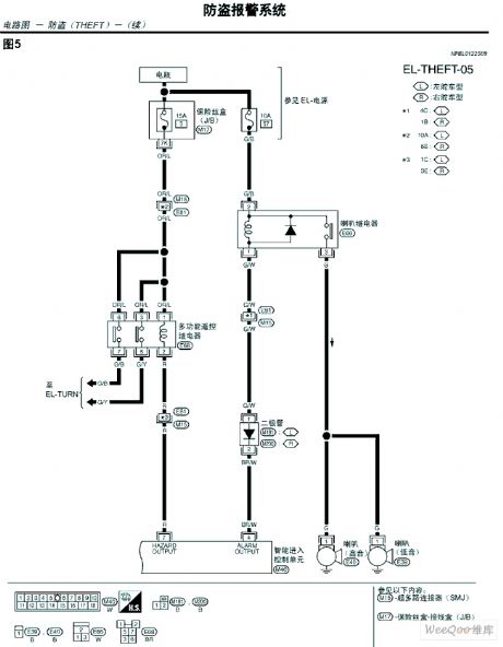
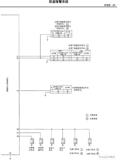
TEANA A33-EL Anti-theft Alarm System Circuit and Schematic Diagram Five
Published:2011/7/15 2:21:00 Author:Joyce | Keyword: TEANA , Anti-theft , Alarm , Schematic Diagram
TEANA A33-EL Anti-theft Alarm System Circuit and Schematic Diagram (View)
View full Circuit Diagram | Comments | Reading(828)
TEANA A33-EL Anti-theft Alarm System Circuit and Schematic Diagram Four
Published:2011/7/15 2:20:00 Author:Joyce | Keyword: TEANA, Anti-theft , Alarm , Schematic Diagram
TEANA A33-EL Anti-theft Alarm System Circuit and Schematic Diagram (View)
View full Circuit Diagram | Comments | Reading(1226)
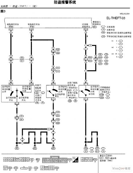
TEANA A33-EL Anti-theft Alarm System Circuit and Schematic Diagram Three
Published:2011/7/15 2:19:00 Author:Joyce | Keyword: TEANA , Anti-theft, Alarm , Schematic Diagram
TEANA A33-EL Anti-theft Alarm System Circuit and Schematic Diagram (View)
View full Circuit Diagram | Comments | Reading(736)
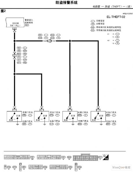
TEANA A33-EL Anti-theft Alarm System Circuit and Schematic Diagram Two
Published:2011/7/15 2:18:00 Author:Joyce | Keyword: TEANA , Anti-theft , Alarm, Schematic Diagram
TEANA A33-EL Anti-theft Alarm System Circuit and Schematic Diagram (View)
View full Circuit Diagram | Comments | Reading(868)
TEANA A33-EL Anti-theft Alarm System Circuit and Schematic Diagram One
Published:2011/7/15 2:17:00 Author:Joyce | Keyword: TEANA , Anti-theft, Alarm , Schematic Diagram
TEANA A33-EL Anti-theft Alarm System Circuit and Schematic Diagram (View)
View full Circuit Diagram | Comments | Reading(865)
Brightness automatic control circuit
Published:2011/7/19 8:15:00 Author:Fiona | Keyword: automatic control
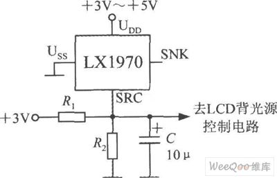
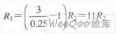
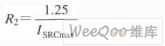
When the ambient brightness turns dark obviously,LX1970 can automatically turn the LCD backlight to make white LED light.Brightness automatic control circuit is shown as above.Using resistors R1 and R2 can set to control the brightness's minimum and maximum.Changing the capacity of capacitor C the capacity can adjust the response time and filter out 50 Hz power grid interference.LX1970 uses +3.3 ~ +5 V power supply.When only using SRC end,SNK end should be hung in the air.Assumed that the circuit requires 0.25 ~ 1.25V output voltage to drive the white LED,0.25V represents the minimum of LED brightness,1.25V represents the brightness's maximum.
(View)
View full Circuit Diagram | Comments | Reading(726)
Remote control of the wireless proportion motor circuit
Published:2011/7/19 8:43:00 Author:Fiona | Keyword: wireless proportion motor, Remote control
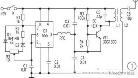
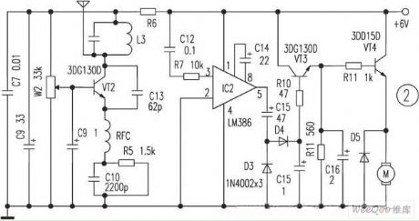
Take R6 is 200Ω,then connect the circuit well in the actual to achieve the function described in the text. However,in the process of the actual production,when producing an inductor,it is found that the alignment of two frequency is more difficult,but according to the method described in the text,it is easy to solve.If the circuit uses with the oscilloscope (100Hz) in the debugging process,effect is better. The circuit structure is reasonable and can be extended to other circuits,it is suitable for amateur radio production.
(View)
View full Circuit Diagram | Comments | Reading(689)
Audi A6-level height adjustment system circuit Figure 2
Published:2011/7/17 2:21:00 Author:Fiona | Keyword: level height adjustment system
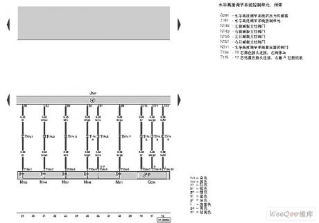
Audi A6-level height adjustment system circuit is shown as above:
(View)
View full Circuit Diagram | Comments | Reading(437)
Audi A6-level height adjustment system circuit
Published:2011/7/17 2:22:00 Author:Fiona | Keyword: level height adjustment system
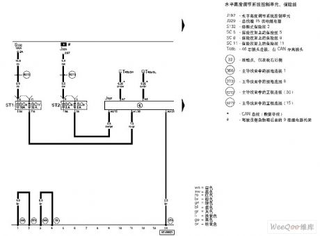
Audi A6-level height adjustment system circuit is shown as above:
(View)
View full Circuit Diagram | Comments | Reading(551)
Ultra low working voltage white LED drive circuit
Published:2011/7/17 2:24:00 Author:Fiona | Keyword: drive, Ultra low working voltage

Ultra low working voltage white LED drive circuit is shown as above:
(View)
View full Circuit Diagram | Comments | Reading(743)
0~20v,1A regulated power supply circuit
Published:2011/7/17 7:36:00 Author:Fiona | Keyword: regulated power supply
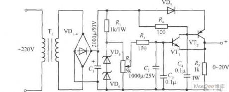
0~20v,1A regulated power supply circuit is shown as above:
(View)
View full Circuit Diagram | Comments | Reading(1507)
| Pages:1510/2234 At 2015011502150315041505150615071508150915101511151215131514151515161517151815191520Under 20 |
Circuit Categories
power supply circuit
Amplifier Circuit
Basic Circuit
LED and Light Circuit
Sensor Circuit
Signal Processing
Electrical Equipment Circuit
Control Circuit
Remote Control Circuit
A/D-D/A Converter Circuit
Audio Circuit
Measuring and Test Circuit
Communication Circuit
Computer-Related Circuit
555 Circuit
Automotive Circuit
Repairing Circuit