
Circuit Diagram
Index 1512
FUKANG AL4 Automatic Transmission Circuit
Published:2011/7/18 3:08:00 Author:Joyce | Keyword: FUKANG , Automatic Transmission
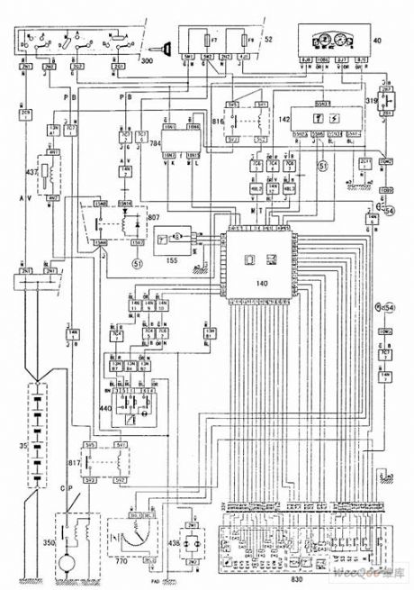
15-generator 35-battery 40- dashboard 50- 6 fuse boxes 52- 13 fuse boxes 140-electronic control units of automatic transmission 142-electronic control units of engine fuel injection 155-the sensor of output speed 319-brake switch 350- starter
437- lock-up mechanism of the gear lever
438-baffle plate floodlight 440-program selector 770-throttle potentiometer 784-16 channel diagnosis interface 807-double sealed relays
816-the shift lever lock-up relay 817-start-banned relay 830-electrical equipment connection box of the automatic transmission (View)
View full Circuit Diagram | Comments | Reading(2783)
An Kai Motor Bus ABS/ASR Circuit
Published:2011/7/18 3:07:00 Author:Joyce | Keyword: An Kai, Motor Bus , ABS/ASR
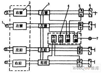
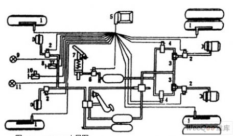
The circuit of ABS is as shown in figure 1, and the layout of ABS/ASR is as shown in figure 2.
1-sensor 2-input processing circuit 3-calculator 4-diagnostic circuit 5-output processing circuit 6-regulator 7-ABS warning light.
1-sensor 2-regulator 3- two-port valve 4-ASR electromagnetic valve 5-control module 6-proportional valve 7-function valve 8、10-function converter 9、ABS warning light 101-ASR light
(View)
View full Circuit Diagram | Comments | Reading(1214)
Low Noise Broadband Operational Amplifier Circuit
Published:2011/7/15 6:48:00 Author:Sue | Keyword: Low Noise, Broadband, Operational Amplifier
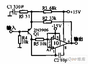
The circuit can increase the operational amplifier 101's gain bandwidth product to 100MHz. The circuit's input noise will be reduced to 0.5 μV(frequency band is 10KHz, signal source internal resistance value is 600Ω). The circuit moves 101's input grade out of inner circuit and uses the capacitor C2 to compose positive feedback compensating circuit which will increase the slew rate by 30 times. (View)
View full Circuit Diagram | Comments | Reading(448)
High-precision Linear Amplifier Circuit
Published:2011/7/18 1:26:00 Author:Sue | Keyword: High-precision, Linear, Amplifier
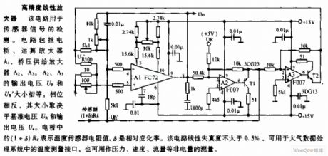
The circuit is used to detect sensor signal. The circuit consists of bridge, operational amplifier A1, bridge voltage supply amplifier A2,A3. The output voltage UR,UR' of A2,A3 have the same value and opposite phases. Their values are decided by the base voltage UR and output voltage UO. In the bridge, (1+δ)R4 stands for the resistance value of the temperature sensor. δ is the relative variable ratio.The circuit's linear distortion is not larger than 0.5%, which can be use as the temperature measurement interface in air data processing system. It can also be used to measure the non electrical quantity such as pressure, speed and flow rate. (View)
View full Circuit Diagram | Comments | Reading(863)
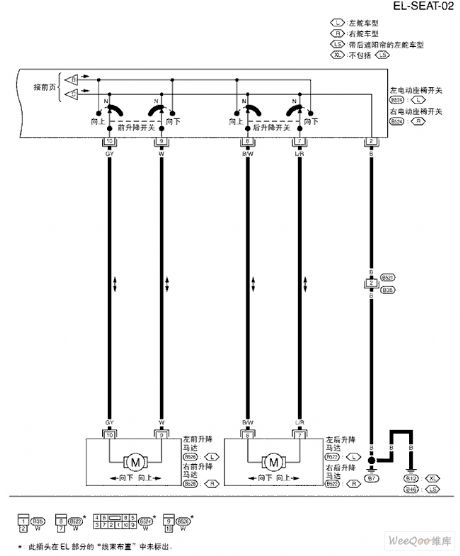
TEANA A33-EL Motor-driven Seats Schematic Diagram and Circuit Four
Published:2011/7/15 2:35:00 Author:Joyce | Keyword: TEANA , Motor-driven Seats , Schematic Diagram
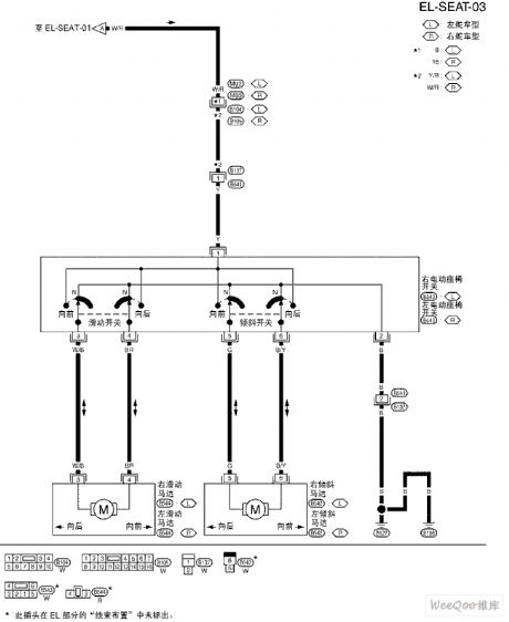
TEANA A33-EL Motor-driven Seats Schematic Diagram and Circuit (View)
View full Circuit Diagram | Comments | Reading(863)
TEANA A33-EL Sound Antenna Circuit Two
Published:2011/7/15 2:36:00 Author:Joyce | Keyword: TEANA , Sound , Antenna
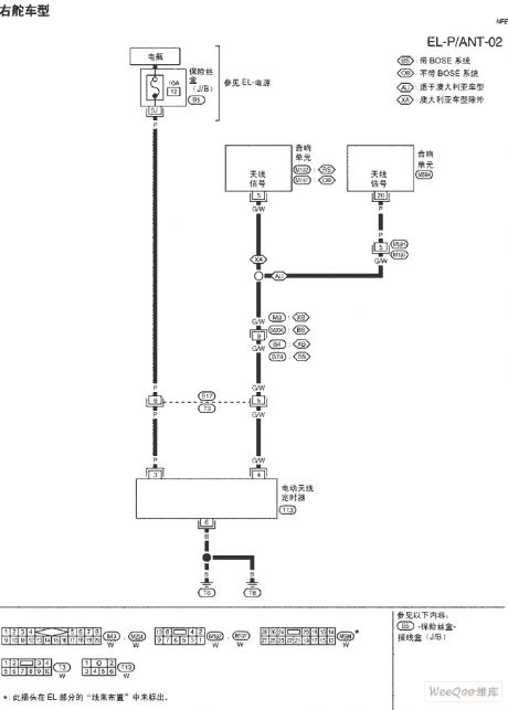
TEANA A33-EL Sound Antenna Circuit (View)
View full Circuit Diagram | Comments | Reading(761)
TEANA A33-EL Sound Antenna Circuit One
Published:2011/7/15 2:37:00 Author:Joyce | Keyword: TEANA , Sound , Antenna
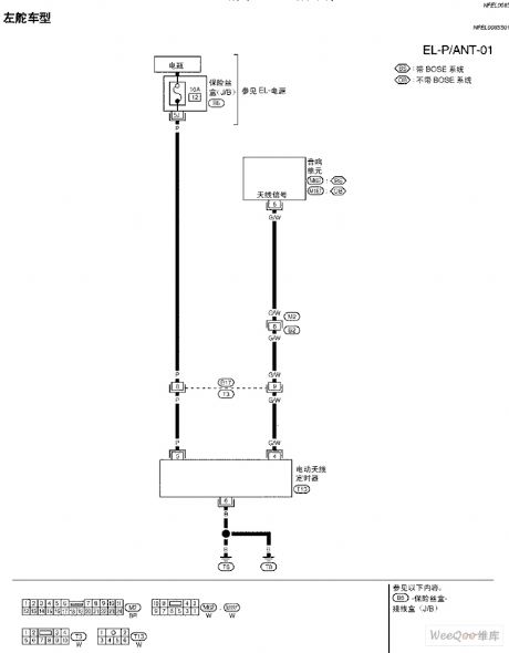
TEANA A33-EL Sound Antenna Circuit (View)
View full Circuit Diagram | Comments | Reading(814)
TEANA A33-EL Motor-driven Seats Schematic Diagram and Circuit Three
Published:2011/7/15 2:31:00 Author:Joyce | Keyword: TEANA, Motor-driven Seats , Schematic Diagram
TEANA A33-EL Motor-driven Seats Schematic Diagram and Circuit (View)
View full Circuit Diagram | Comments | Reading(822)
MOSFET Tube Drive Digital Modulation Output Circuit
Published:2011/7/18 3:02:00 Author:Sue | Keyword: MOSFET Tube, Drive, Digital Modulation, Output
The picture shows the MOSFET tube drive digital modulation output circuit. (View)
View full Circuit Diagram | Comments | Reading(1050)
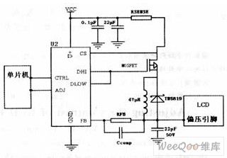
3W High-power LED Drive Circuit
Published:2011/7/18 1:01:00 Author:Sue | Keyword: High-power, LED, Drive

The high-power LED easy driver is the one used in the high-power white light, but the difference is that I here use the 3W LED. The circuit will input1.2v working voltage(high capacitance NI-MH battery).The current is about 1.4-1.8A, which has a poor efficiency of about 70%. If the 150Ω resistor is replaced by a 200Ω one, and the input current is reduced to 1.0-1.3A, then a little copper sheet of an area of 3 cm² should be added on that D882 for heat radiation. I used a diagonal plier to remove the head of D882(to reduce the volume), and then welded it on the copper sheet directly. (View)
View full Circuit Diagram | Comments | Reading(4114)
TEANA A33-EL Heating Seats Circuit
Published:2011/7/15 2:39:00 Author:Joyce | Keyword: TEANA , Heating Seats
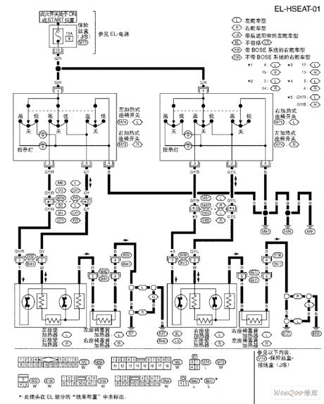
TEANA A33-EL Heating Seats Circuit (View)
View full Circuit Diagram | Comments | Reading(816)
SC41344 general infrared, ultrasonic or RF remote control launch coding circuit
Published:2011/7/18 8:57:00 Author:Christina | Keyword: general, infrared, ultrasonic, RF, remote control, launch, coding
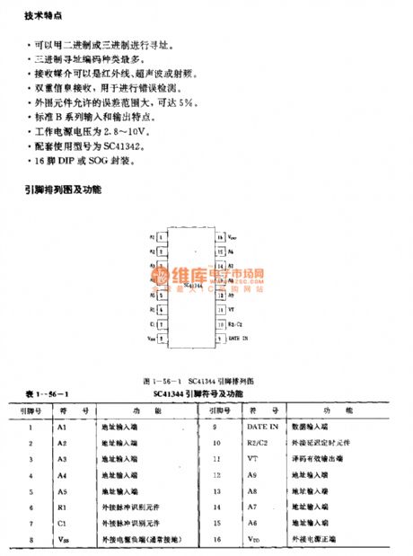
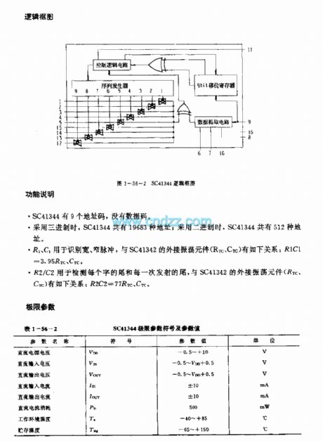
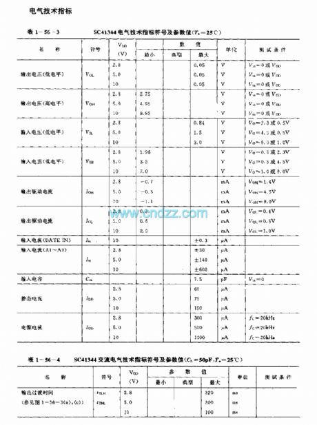
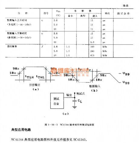
The SC41344 is designed as one kind of infrared, ultrasonic or RF remote control launch coding circuit. The internal circuit is composed of the sequence generator, control logic circuit,9-bit shift register,data extraction circuit and the latch circuit.
Features
It uses the binary or ternary to find the address;The ternary addressing coding has the most kinds;The launch media can be the infrared ray, ultrasonic or the RF;The double information launch can be used to detect the error;The external RC components form the oscillating circuit, so there is no need of the crystal oscillator;The external components has the allowable error range of 5%;The standard B series input and output features;The power voltage is 2.8-10V;The 16-pin DIP or SOG package;The matching model is SC41342.
(View)
View full Circuit Diagram | Comments | Reading(979)
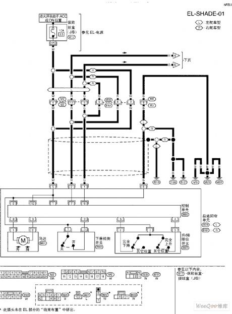
TEANA A33-EL Rear Abat Vent Circuit Two
Published:2011/7/15 2:30:00 Author:Joyce | Keyword: TEANA , Rear Abat Vent
TEANA A33-EL Rear Abat Vent Circuit (View)
View full Circuit Diagram | Comments | Reading(853)
TEANA A33-EL Rear Abat Vent Circuit One
Published:2011/7/15 2:28:00 Author:Joyce | Keyword: TEANA, Rear Abat Vent
TEANA A33-EL Rear Abat Vent Circuit (View)
View full Circuit Diagram | Comments | Reading(963)
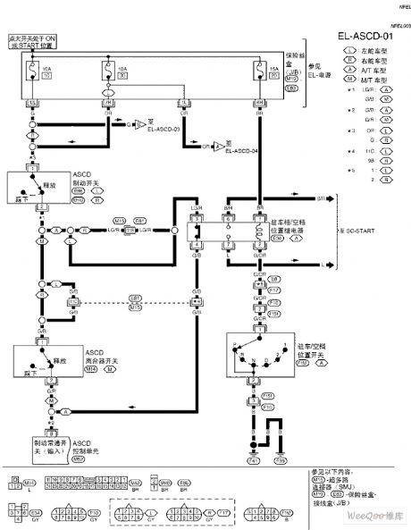
TEANA A33-EL Automatic Speed Control Device Schematic Diagram and Circuit Five
Published:2011/7/15 8:08:00 Author:Joyce | Keyword: TEANA , Automatic, Speed Control Device , Schematic Diagram
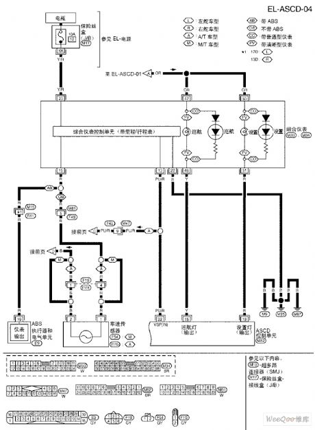
TEANA A33-EL Automatic Speed Control Device Schematic Diagram and Circuit (View)
View full Circuit Diagram | Comments | Reading(1006)
Dual Track Loudspeaker Protection Circuit
Published:2011/7/18 0:46:00 Author:Sue | Keyword: Dual Track, Loudspeaker, Protection
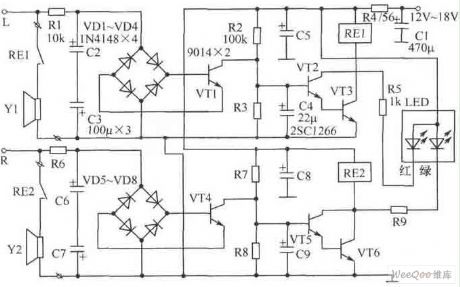
The picture shows the dual track loudspeaker protection circuit. It is designed that the left and right tracks are working independently. In the picture(to take the left track for example), R2, C4 and VT2,VT3 compose starting delay circuit which can prevent the large starting current from shocking the loudspeaker.
Component choice:We can choose Φ3mm high-brightness two-tone LED as LED. Because of the reason that LED has different working currents, so R5,R9 have adjustable parameters. At the same time, LED and current-limiting resistor R5,R9 are connected to relay RE1,RE2 in parallel, which can prevent inverse peak voltage and can prevent VT2,VT3,VT5,VT6 frombeing punctured. The best choice for C4,C9 is low-leakage tantalum capacitor. (View)
View full Circuit Diagram | Comments | Reading(1919)
TEANA A33-EL Automatic Speed Control Device Schematic Diagram and Circuit Four
Published:2011/7/15 8:07:00 Author:Joyce | Keyword: TEANA , Automatic, Speed Control Device, Schematic Diagram

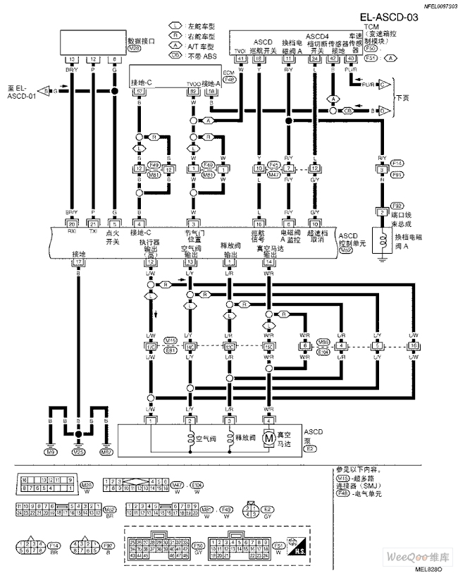 TEANA A33-EL Automatic Speed Control Device Schematic Diagram and Circuit (View)
View full Circuit Diagram | Comments | Reading(774)
SC41342 general infrared, ultrasonic or RF remote control launch coding circuit
Published:2011/7/18 9:01:00 Author:Christina | Keyword: general, infrared, ultrasonic, RF, remote control, launch, coding
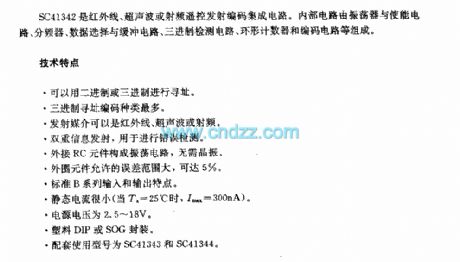
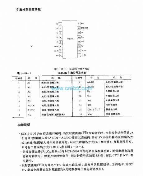
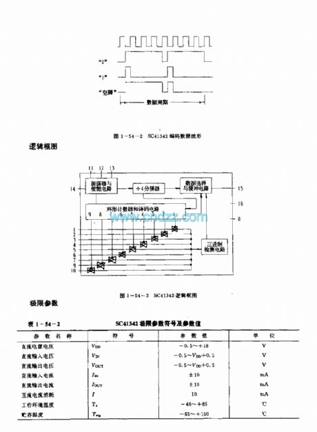
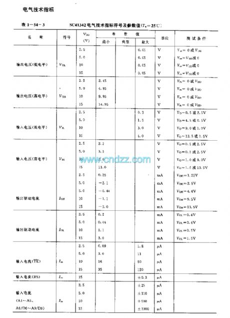
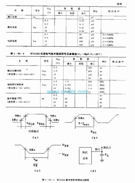
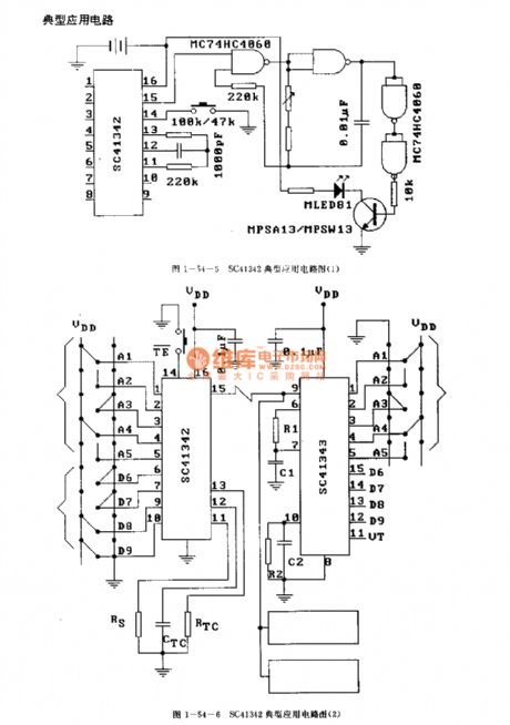
The SC41342 is designed as one kind of infrared, ultrasonic or RF remote control launch coding circuit. The internal circuit is composed of the oscillator, the enable circuit, the frequency divider, the data selection and buffer circuit, the ternary detection circuit, the annular counter and the coding circuit.
Features
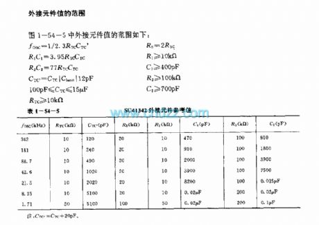
It uses the binary or ternary to find the address;The ternary addressing coding has the most kinds;The launch media can be the infrared ray, ultrasonic or the RF;The double information launch can be used to detect the error;The external RC components form the oscillating circuit, so there is no need of the crystal oscillator;The external components has the allowable error range of 5%;The standard B series input and output features;The power voltage is 2.8-18V;The plastic DIP or SOG package;The static current is small;The matching model is SC41343 and the SC41344.
(View)
View full Circuit Diagram | Comments | Reading(1054)
TEANA A33-EL Automatic Speed Control Device Schematic Diagram and Circuit Three
Published:2011/7/15 8:06:00 Author:Joyce | Keyword: TEANA , Automatic , Speed Control Device, Schematic Diagram
TEANA A33-EL Automatic Speed Control Device Schematic Diagram and Circuit (View)
View full Circuit Diagram | Comments | Reading(832)
TEANA A33-EL Automatic Speed Control Device Schematic Diagram and Circuit Two
Published:2011/7/15 8:05:00 Author:Joyce | Keyword: TEANA, Automatic , Speed Control Device, Schematic Diagram
TEANA A33-EL Automatic Speed Control Device Schematic Diagram and Circuit (View)
View full Circuit Diagram | Comments | Reading(872)
| Pages:1512/2234 At 2015011502150315041505150615071508150915101511151215131514151515161517151815191520Under 20 |
Circuit Categories
power supply circuit
Amplifier Circuit
Basic Circuit
LED and Light Circuit
Sensor Circuit
Signal Processing
Electrical Equipment Circuit
Control Circuit
Remote Control Circuit
A/D-D/A Converter Circuit
Audio Circuit
Measuring and Test Circuit
Communication Circuit
Computer-Related Circuit
555 Circuit
Automotive Circuit
Repairing Circuit