
Circuit Diagram
Index 1511
Astable circuit about pulse width adjustment fund
Published:2011/7/17 7:29:00 Author:Fiona | Keyword: pulse width adjustment fund
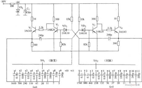
Astable circuit about pulse width adjustment fund is shown as above:
(View)
View full Circuit Diagram | Comments | Reading(571)
Single chip microcomputer and CF card interface circuit
Published:2011/7/17 7:31:00 Author:Fiona | Keyword: Single chip microcomputer, interface
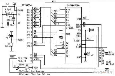
Single chip microcomputer and CF card interface circuit is shown as above:
(View)
View full Circuit Diagram | Comments | Reading(1419)
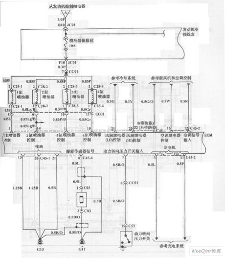
Fuel Injection System Circuit of Hyundai Sonata with V4 Cylinder Engine (6)
Published:2011/7/18 3:21:00 Author:Sue | Keyword: Fuel Injection, Hyundai Sonata, V4 Cylinder
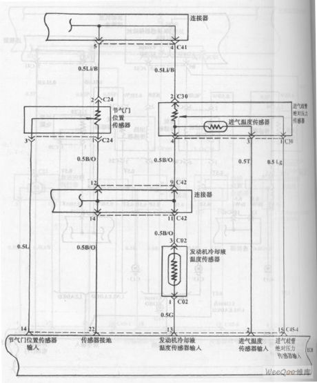
The picture shows the fuel injection system circuit of Hyundai Sonata with V4 cylinder engine. (View)
View full Circuit Diagram | Comments | Reading(1005)
MC14469 general addressable asynchronous launch or receiving circuit
Published:2011/7/18 6:50:00 Author:Christina | Keyword: general, addressable, asynchronous, launch, receiving circuit
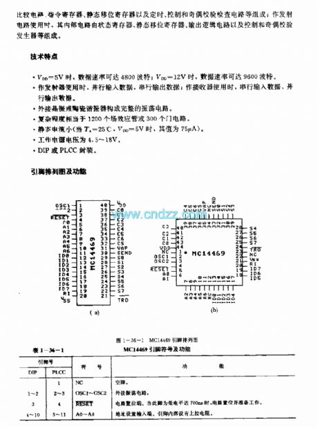
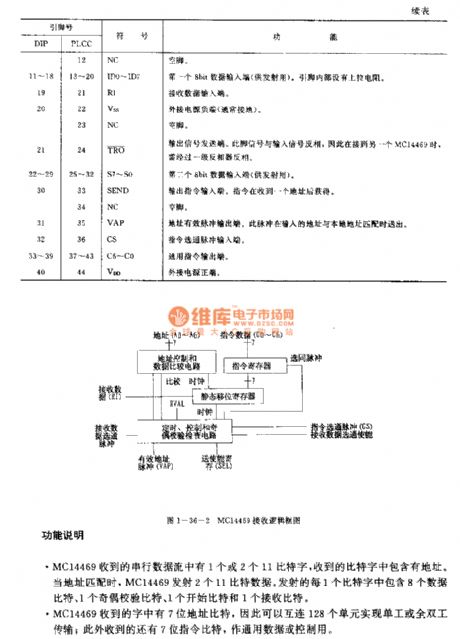
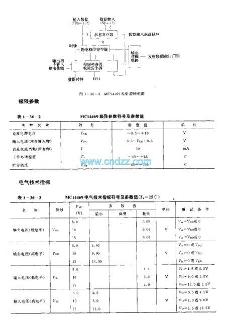
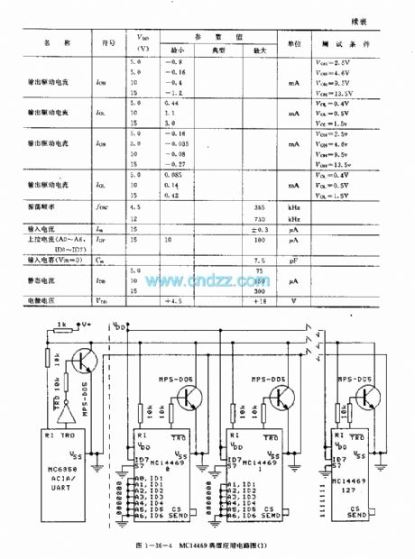
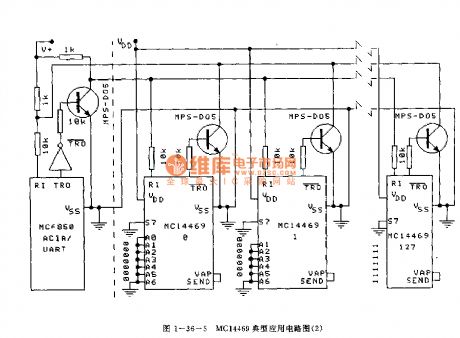
The MC14469 is designed as one kind of general addressable asynchronous launch or receiving circuit that can be used in the remote control analog to digital conversion, the remote control microprocessor and control the digital converter which is connected with the host or the microprocessor. When it is used as the receiving circuit, the internal circuit is composed of the address control and data comparison circuit, the instruction register, the static shift register and the timing, control and parity checking circuit; when it is used as the transmitter circuit, the internal circuit is composed of the status register, the static shift register, the output logic circuit and the control and parity generator.
(View)
View full Circuit Diagram | Comments | Reading(1109)
Fuel Injection System Circuit of Hyundai Sonata with V4 Cylinder Engine (5)
Published:2011/7/18 3:19:00 Author:Sue | Keyword: Fuel Injection, Hyundai Sonata, V4 Cylinder
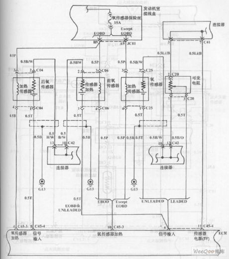
The picture shows the fuel injection system circuit of Hyundai Sonata with V4 cylinder engine. (View)
View full Circuit Diagram | Comments | Reading(1146)
Fuel Injection System Circuit of Hyundai Sonata with V4 Cylinder Engine (3)
Published:2011/7/18 3:16:00 Author:Sue | Keyword: Fuel Injection, Hyundai Sonata, V4 Cylinder
The picture shows the fuel injection system circuit of Hyundai Sonata with V4 cylinder engine. (View)
View full Circuit Diagram | Comments | Reading(1345)
Fuel Injection System Circuit of Hyundai Sonata with V6 Cylinder Engine (1)
Published:2011/7/18 3:14:00 Author:Sue | Keyword: Fuel Injection, Hyundai Sonata, V6 Cylinder
The picture shows the fuel injection system circuit of Hyundai Sonata with V6 cylinder engine. (View)
View full Circuit Diagram | Comments | Reading(895)
MC9481 (electronic toys) remote control transmitter coding circuit
Published:2011/7/18 7:17:00 Author:Christina | Keyword: electronic toys, remote control, transmitter, coding
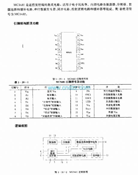
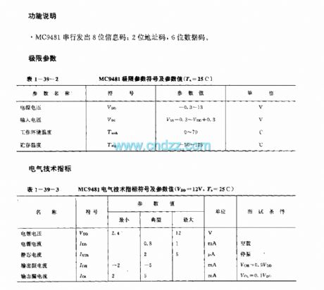
The MC9481 is designed as one kind of remote control transmitter coding circuit that can be used in the electronic toys. The internal circuit is composed of the oscillator, the frequency divider, the data selection and buffer circuit, the serial data generation circuit, the synchronous circuit, the logic control circuit and the buffer circuit. The matching model is MC9482.
(View)
View full Circuit Diagram | Comments | Reading(1359)
MC145030 (cordless phone and half-duplex remote controller) infrared ray, ultrasonic or RF remote control coding and decoding circuit
Published:2011/7/18 7:52:00 Author:Christina | Keyword: cordless phone, half-duplex, remote controller, infrared ray, ultrasonic, RF, remote control, coding, decoding
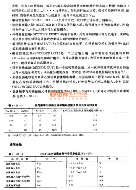
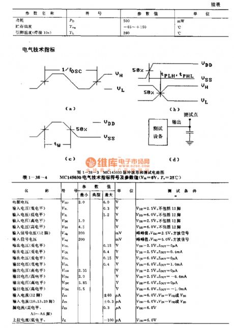
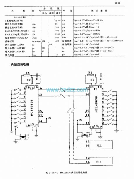
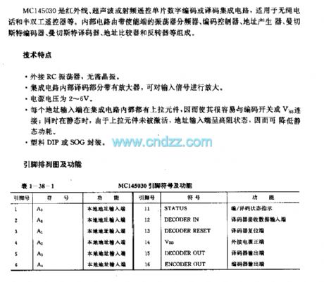
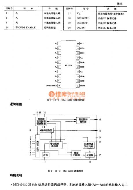
The MC145030 is designed as one kind of infrared ray, ultrasonic or RF remote control coding and decoding circuit that can be used in the cordless phone and half-duplex remote controller. The internal circuit is composed of the oscillator frequency divider with the enable pin, the coding remote controller, the address generator, the Manchester encoder, the Manchester coder, the address comparator and the reverse controller.
Features
It has the external RC oscillator;The internal decoding part of the integrated circuit has the amplifier to amplify the input signal;The power voltage is 2-6V;Every address port has the pull component in the IC;It is in the plastic DIP or SOG package.
(View)
View full Circuit Diagram | Comments | Reading(1502)
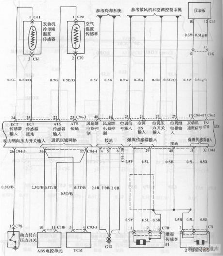
Hyundai Sonata Cooling System Circuit (1)
Published:2011/7/18 3:11:00 Author:Sue | Keyword: Hyundai Sonata, Cooling System
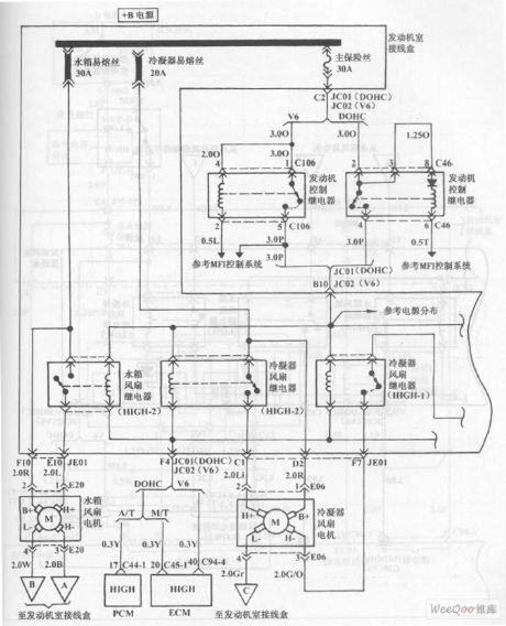
The picture shows the Hyundai Sonata cooling system circuit. (View)
View full Circuit Diagram | Comments | Reading(1418)
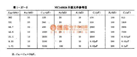
MC145026 general infrared ray, ultrasonic or RF remote control launch coding circuit
Published:2011/7/18 8:09:00 Author:Christina | Keyword: general, infrared ray, ultrasonic, RF, remote control, launch, coding circuit
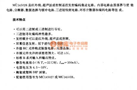
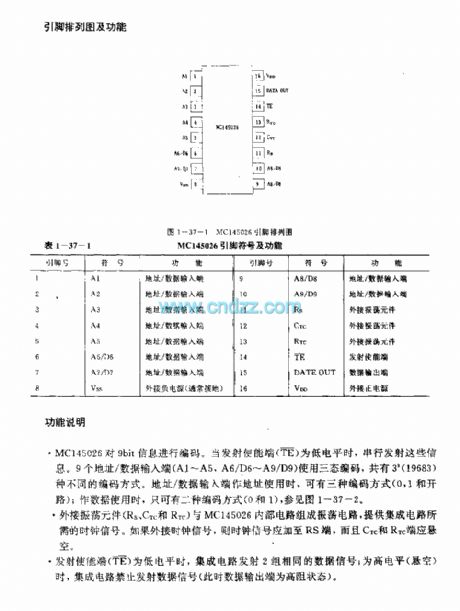
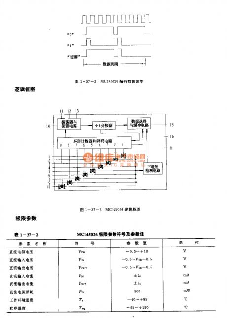
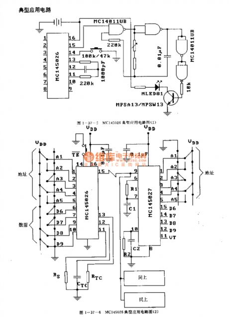
The MC145026 is designed as one kind of general infrared ray, ultrasonic or RF remote control launch coding circuit. The internal circuit is composed of the oscillator, the enable circuit, the frequency divider, the data selection and buffer circuit, the ternary detection circuit, the annular counter and the coding circuit.
Features
It uses the binary or ternary to find the address;The ternary addressing coding has the most kinds;The launch media can be the infrared ray, ultrasonic or the RF;The double information launch can be used to detect the error;The external RC components form the oscillating circuit, so there is no need of the crystal oscillator;The external components has the allowable error range of 5%.
(View)
View full Circuit Diagram | Comments | Reading(2786)
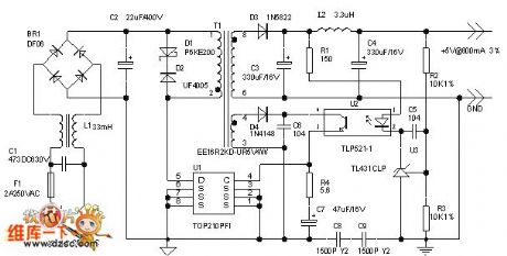
4W Switch-type 5V Stabilized Voltage Direct Current Power Circuit
Published:2011/7/18 6:12:00 Author:Sue | Keyword: Switch-type, Stabilized Voltage, Direct Current, Power
View full Circuit Diagram | Comments | Reading(1012)
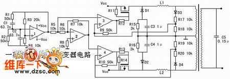
High Efficiency Sine Invertor Circuit
Published:2011/7/15 5:59:00 Author:Sue | Keyword: High Efficiency, Sine, Invertor
View full Circuit Diagram | Comments | Reading(872)
M58480P/M58484P (TV and stereo equipment) 30 functions infrared remote control launch circuits
Published:2011/7/18 8:25:00 Author:Christina | Keyword: TV, stereo equipment, 30 functions, infrared, remote control, launch circuit
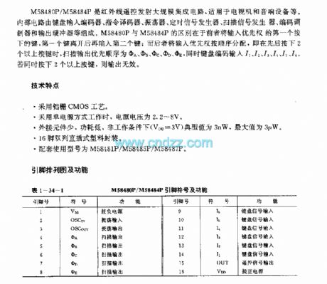
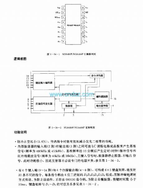
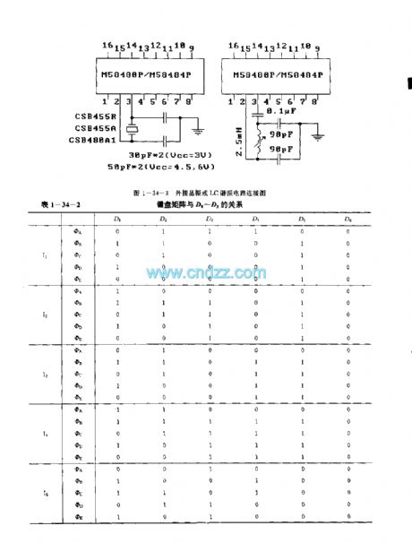
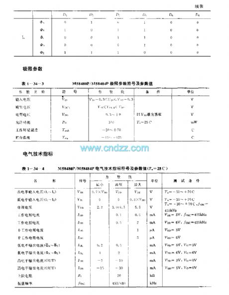
The M58480P and M58484P are designed as the 30 functions infrared remote control launch circuits that can be used in the TVs and stereo equipments. The internal circuit is composed of the keyboard input encoder, the instruction decoder, the oscillator, the timing signal generator, the scanning signal generator, the coding modulator and the output buffer. The difference between the M58480P and M58484P is that the M58480P gives the priority to the first button.
Features
It uses the aluminum gate CMOS technology;When it uses the single power operating mode, the power voltage is 2.2-8V;The external components are little, the power consumption is low, in the non-operating condition, the typical value is 3nW, the maximum value is 3uW;It is in the dual-row DIP plastic package;The matching models are M58481P/M58485P/M58487P.
(View)
View full Circuit Diagram | Comments | Reading(2613)
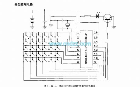
M50U5P/AF/BP/CP (video tape recorder, TV and stereo equipment) 120 functions infrared remote control launch circuits
Published:2011/7/18 8:37:00 Author:Christina | Keyword: video tape recorder, TV, stereo equipment, 120 functions, infrared, remote control, launch circuit
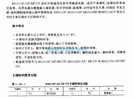
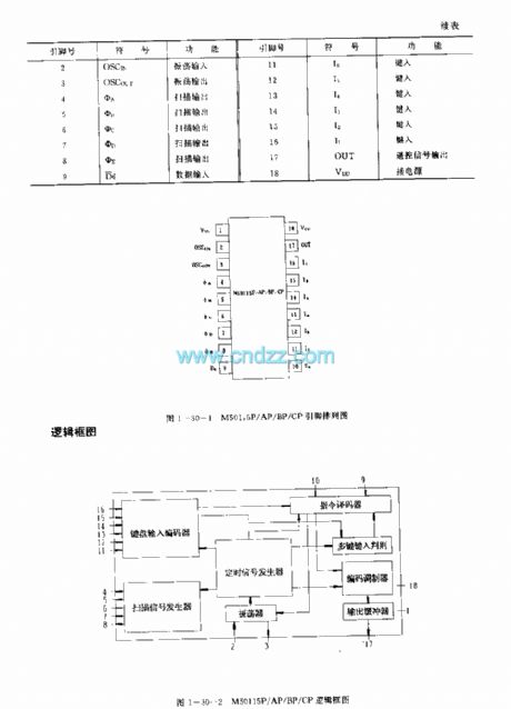
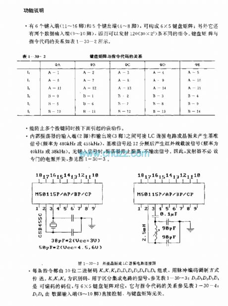
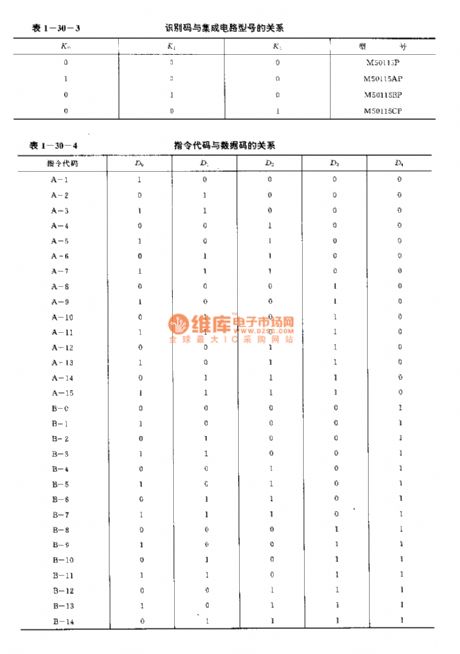
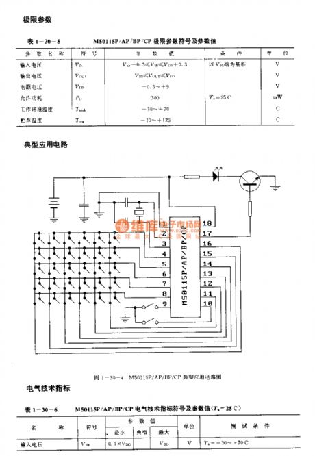
The M50U5P/AF/BP/CP are designed as the infrared remote control launch circuit that can be used in the video tape recorder, TV and stereo equipment applications. The internal circuit is composed of the keyboard input encoder, the instruction decoder, the oscillator, the timing signal generator, the scanning signal generator, the coding modulator and the output buffer. The difference between the M50115P, M50115AP, M50115BP, M50115CP is the identification code.
Features
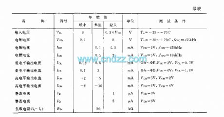
It uses the single power operating mode, the power voltage is 2.2-8V;It uses the 18-pin dual-row DIP plastic package;When the keyboard button is not pressed, the oscillator will stop oscillating to reduce the power consumption;the pulse duty cycle is small;It has less external components, the SNR is high, the great anti-interference ability.
(View)
View full Circuit Diagram | Comments | Reading(1806)
M50142P (TV) infrared remote control launch circuit
Published:2011/7/18 8:46:00 Author:Christina | Keyword: TV, infrared, remote control, launch circuit
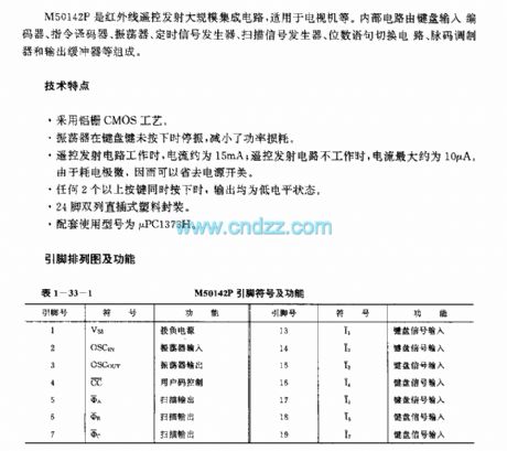
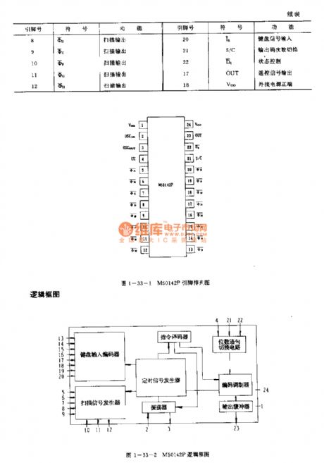
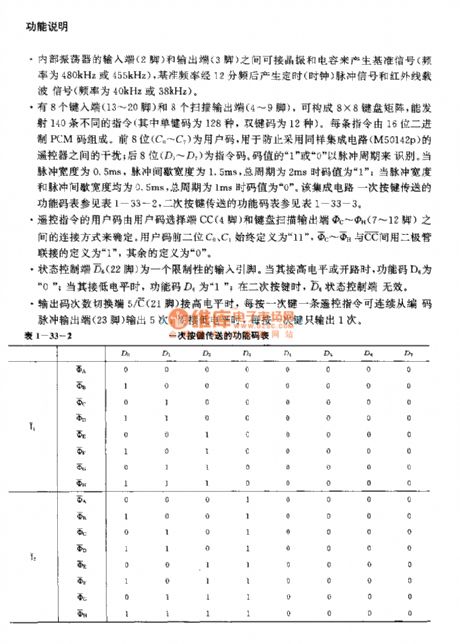
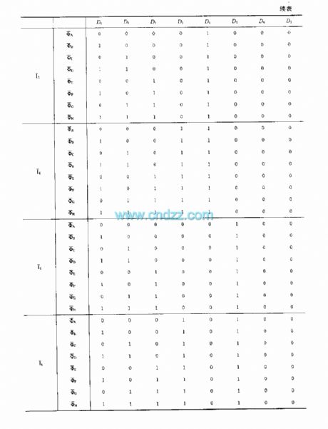
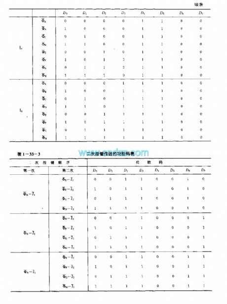
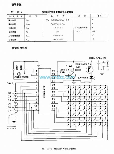
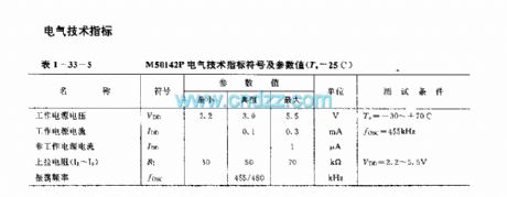
The M50142P is designed as one kind of infrared remote control launch large-scale circuit that can be used in the TVs. The internal circuit is composed of the keyboard input encoder, the instruction decoder, the oscillator, the timing signal generator, the scanning signal generator, the coding modulator and the output buffer.
Features
It uses the aluminum gate CMOS technology;When the keyboard button is not pressed, the oscillator will stop oscillating to reduce the power consumption;When the remote control launch circuit is operating, the current is about 15mA, when the remote control launch circuit is not operating, the current is about 10A;If you press any two or more buttons together, the output is in the low level state;It is in the 24-pin dual-row DIP plastic package;The matching model is uPC1373H.
(View)
View full Circuit Diagram | Comments | Reading(1495)
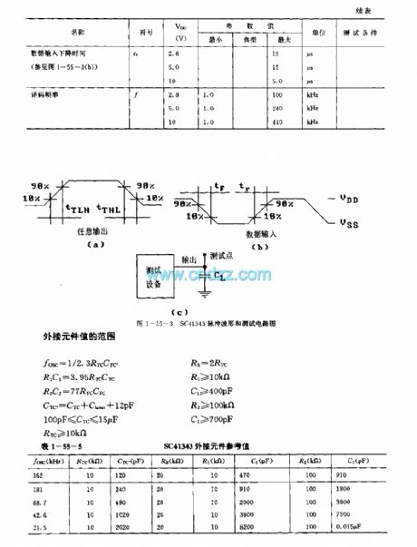
SC41343 general infrared, ultrasonic or RF remote control launch coding circuit
Published:2011/7/18 8:53:00 Author:Christina | Keyword: general, infrared, ultrasonic, RF, remote control, launch, coding
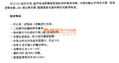
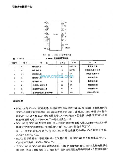
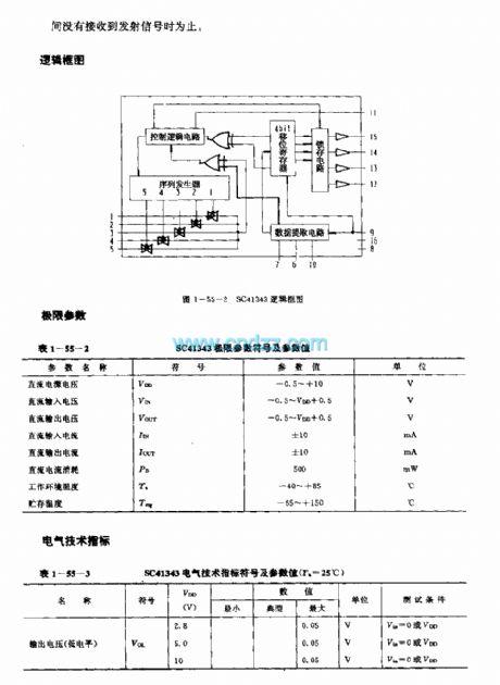
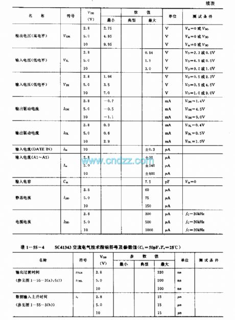
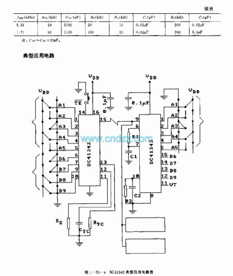
The SC41343 is designed as one kind of infrared, ultrasonic or RF remote control launch coding circuit. The internal circuit is composed of the sequence generator, control logic circuit,4-bit shift register,data extraction circuit and the latch circuit.
Features
It uses the binary or ternary to find the address;The ternary addressing coding has the most kinds;The launch media can be the infrared ray, ultrasonic or the RF;The double information launch can be used to detect the error;The external RC components form the oscillating circuit, so there is no need of the crystal oscillator;The external components has the allowable error range of 5%;The standard B series input and output features;The power voltage is 2.8-10V;The plastic DIP or SOG package;The matching model is SC41342.
(View)
View full Circuit Diagram | Comments | Reading(2142)
Hall Sensor Amplifier Circuit
Published:2011/7/15 6:24:00 Author:Sue | Keyword: Hall, Sensor, Amplifier

C1: use low-leakage capacitor.
I: capacitor's leakage current(DC).
(a) be influenced by capacitor's leakage current. (View)
View full Circuit Diagram | Comments | Reading(2744)
Instrumentation Amplifier Circuit with Program Controlled Integrated Operational Amplification
Published:2011/7/18 7:10:00 Author:Sue | Keyword: Instrumentation Amplifier, Program Controlled, Integrated, Operational Amplification
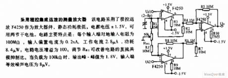
The circuit uses program controlled operational amplifier F4250 as amplifier, which has a low static power. The power voltage is ±1.5V, which can use two dry batteries. The main features of the circuit: Every input terminal's input resistance value over the ground is 100MΩ. Input bias current is 0.2nA. Working current is 2.8μA. Power consumption is 8.4μW. The circuit voltage gain is 100. The circuit alternating current common-mode rejection ratio can be changed by adjusting RW1. When the load is 100kΩ, output peak value is 1.8V and input terminal's equivalent noise voltage is 8μV. (View)
View full Circuit Diagram | Comments | Reading(433)
Program Controlled Gain Amplifier Circuit
Published:2011/7/18 6:27:00 Author:Sue | Keyword: Program Controlled, Gain Amplifier
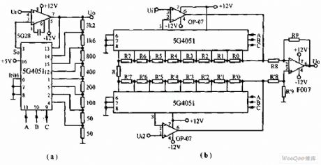
The circuit is differential input program controlled gain amplifier circuit. 5G4051 works as a single-pole eight-throw switch. When its pin 6 has low level, it is corresponding to one state of A,B,C. When we connect the channel and change one state, the feedback resistance value will be changed once and the corresponding voltage gain will be changed once. The states of the two 5G4051 are changing simultaneously and the output voltage will be differential amplified by F007. (View)
View full Circuit Diagram | Comments | Reading(977)
| Pages:1511/2234 At 2015011502150315041505150615071508150915101511151215131514151515161517151815191520Under 20 |
Circuit Categories
power supply circuit
Amplifier Circuit
Basic Circuit
LED and Light Circuit
Sensor Circuit
Signal Processing
Electrical Equipment Circuit
Control Circuit
Remote Control Circuit
A/D-D/A Converter Circuit
Audio Circuit
Measuring and Test Circuit
Communication Circuit
Computer-Related Circuit
555 Circuit
Automotive Circuit
Repairing Circuit