
Circuit Diagram
Index 1515
TEANA A33-EL Sound Remote Control Circuit
Published:2011/7/14 20:51:00 Author:Joyce | Keyword: TEANA , Sound, Remote Control
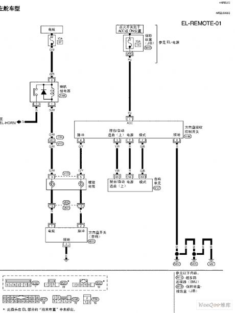
TEANA A33-EL Sound Remote Control Circuit (View)
View full Circuit Diagram | Comments | Reading(704)
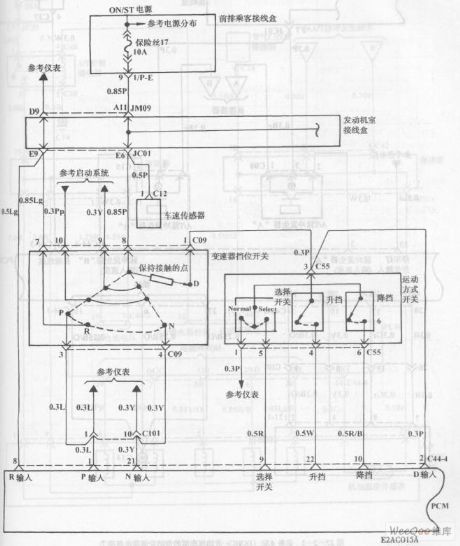
Automatic Transmission Circuit of Hyundai Sonata with V6 Cylinder Engine (1)
Published:2011/7/18 2:11:00 Author:Sue | Keyword: Automatic Transmission, Hyundai Sonata, V6 Cylinder
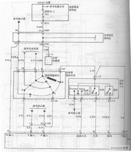
The picture shows the automatic transmission circuit of Hyundai Sonata with V6 cylinder engine. (View)
View full Circuit Diagram | Comments | Reading(841)
Automatic Transmission Circuit of Hyundai Sonata with V4 Cylinder Engine (3)
Published:2011/7/18 2:26:00 Author:Sue | Keyword: Automatic Transmission, Hyundai Sonata, V4 Cylinder
The picture shows the automatic transmission circuit of Hyundai Sonata with V4 cylinder engine. (View)
View full Circuit Diagram | Comments | Reading(922)
Automatic Transmission Circuit of Hyundai Sonata with V4 Cylinder Engine (2)
Published:2011/7/18 2:20:00 Author:Sue | Keyword: Automatic Transmission, Hyundai Sonata, V4 Cylinder
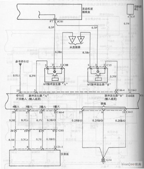
The picture shows the automatic transmission circuit of Hyundai Sonata with V4 cylinder engine. (View)
View full Circuit Diagram | Comments | Reading(835)
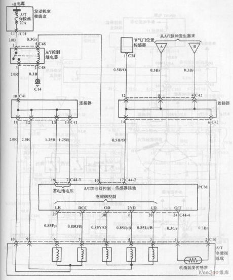
Automatic Transmission Circuit of Hyundai Sonata with V4 Cylinder Engine (1)
Published:2011/7/18 2:18:00 Author:Sue | Keyword: Automatic Transmission, Hyundai Sonata, V4 Cylinder
The picture shows the automatic transmission circuit of Hyundai Sonata with V4 cylinder engine. (View)
View full Circuit Diagram | Comments | Reading(1094)
Fuel Injection System Circuit of Hyundai Sonata with V6 Cylinder Engine (2)
Published:2011/7/18 2:31:00 Author:Sue | Keyword: Fuel Injection, Hyundai Sonata, V6 Cylinder
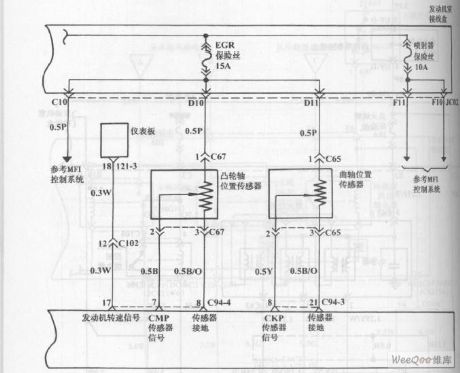
The picture shows the fuel injection system circuit of Hyundai Sonata with V6 cylinder engine. (View)
View full Circuit Diagram | Comments | Reading(838)
Hall Sensor Signal Amplifier Circuit
Published:2011/7/15 6:30:00 Author:Sue | Keyword: Hall, Sensor, Signal Amplifier
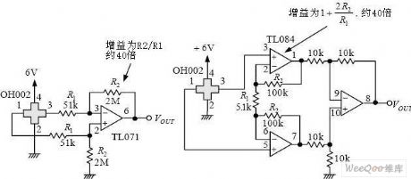
R2: gain is R2/R1, about 40 times.
TL084:gain is 1+2R2/R1, about 40 times. (View)
View full Circuit Diagram | Comments | Reading(2649)
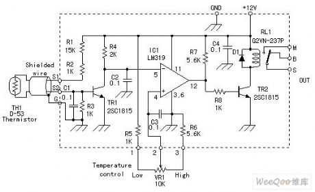
NTC Thermal Resistor Temperature Controller Circuit
Published:2011/7/15 6:14:00 Author:Sue | Keyword: Thermal Resistor, Temperature Controller
View full Circuit Diagram | Comments | Reading(2453)
High Quality Dual Channel Mega Bass Circuit
Published:2011/7/15 1:40:00 Author:Joyce | Keyword: High Quality , Dual Channel, Mega Bass
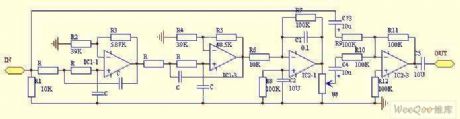
Principle of the circuit: After the input signal goes through low pass processing with changing slope of 24 db/oc by a four-order low pass filter composed of IC1-1 and other peripheral components (fc = 70 Hz, A = 8.2 db in the circuit), it is buffered and amplified for 10 times by the inverting AC amplifier which is IC2-1 centered before it is output. Low frequency signals which have been greatly enhanced and the original signals will be sent to IC2-3 through C4, C3 respectively to be mixed, and the mixed signals will be output via C5. W controls the mixing amount of low frequency signals and original signals. In order to guarantee the output signals through C5 are authentic when W is shut up, its gain at this stage is set to be 0 dB.
(View)
View full Circuit Diagram | Comments | Reading(3149)
Pen Type Rays Dosemeter
Published:2011/7/18 2:45:00 Author:Joyce | Keyword: Pen , Rays , Dosemeter

PDM-112 Pen Type Rays Dosemeter
PDM112 is an individual dosemeter of people engaging in γ and X-ray irradiationIt uses silicon semiconductor sensor and its measurement is accurate and rapidIt has four-digital LCD display Its pen structure is small and exquisite, and makes it convenient to carry with .Technology indexDetectionitems: X and γ raysDisplay : four-digital LCDdisplay readings, data storage, super range, low power Sensor : silicon semiconductor electronic sensorsMeasuring range: 1-9999μSV Measurement accuracy: ±10% (1-9.999uSv)
Energy range : 40 keV-3 MeV Electrical source : button cells ,which can be used for about 500 hourswork environment:0-45 ℃ , < 90% RHOverall dimension : 145×30×12mmWeight: 150g
Standard configuration: main engine, battery, instructions and related material (View)
View full Circuit Diagram | Comments | Reading(444)
VHF 0.5 W TV Transmitter Circuit
Published:2011/7/15 21:07:00 Author:Joyce | Keyword: VHF, 0.5 W , TV, Transmitter

The TV transmitter introduced here can send audio and video signals of satellite television receivers, VCDs and video recorders in open circuit, and receives signals with open antennas. It is suitable for self-made programs of working units, schools, and factories. When folded dipole antenna is used to send signals, the covered distance is longer than 800 m.
The circuitry is as shown in figure 1.IC1 is a dedicated circuit for TV RF modulators.It will choose SAW oscillator of same frequency point to modulate audio and video signals into RF signals of TV1 ~ 12 channels. Incomplete signals and sub wave signals will be filtered out by filter network A1 before RF signals output by IC1 is coupled to RF power amplifier circuit by C15 to be amplified and sent out. (View)
View full Circuit Diagram | Comments | Reading(5420)
The phase detection circuit composed of MAX4521
Published:2011/7/15 22:18:00 Author:Borg | Keyword: phase detection circuit
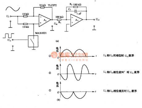
This is a phase detection circuit composed of computing amplifier TLC072 and analog switch MAX4521, which is fitted in PLL circuits or lock amplifiers. The voltage of the power supply is ±5V, the LEV of input and output signals is under ±4V, the working frequency is 10HZ~1OOkHZ. Ui1 and Ui2 are the input sine wave and square wave respectively, the duty cycle of the square wave is 50%, the output waveform of A1 is U. see as figure 7-15(b), when Ui1 and Ui2 are in the same phase, the output of A1 is shown as the waveform of ① in figure (b); when Ui1 and Ui2 are in the phases that differ 90°, the output of A1 is shown as the waveform of ② in figure (b). (View)
View full Circuit Diagram | Comments | Reading(2276)
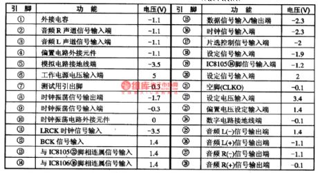
AN262—the record/playback preamplifier integrated circuit
Published:2011/7/15 21:31:00 Author:Borg | Keyword: record/playback preamplifier, integrated circuit
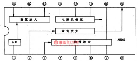
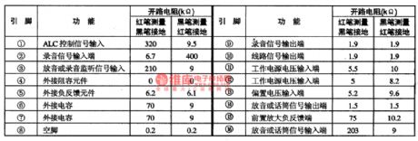
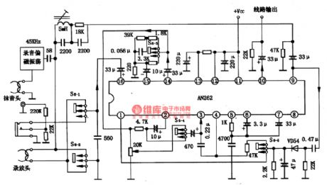
AN262 is a record/playback preamplifier integrated circuit produced by Panasonic, which is used in radios and video recorders, it is also used in compounded stereos.1. the internal circuit and pin functionsAN262 contains the playback and microphone preamplifier circuit, ALC circuit, recording amplifier circuit, playback amplifier circuit, power supply circuit and so on. The IC is in 16-pin dual-line amplifier circuit, whose internal circuit is shown in figure 1 and pin functions and data in table 1.
(View)
View full Circuit Diagram | Comments | Reading(2303)
The pulse width modulation circuit composed of 74HCUO4
Published:2011/7/17 20:46:00 Author:Borg | Keyword: pulse width, modulation circuit
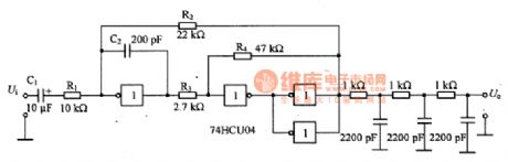
In the figure is the pulse width modulation circuit composed of 74HCUO4. this is a multi-resonance oscillator composed of the Miller integrating circuit and time lag comparing circuit, if the rectangular wave duty cycle is changed by the input low frequency signal of R1, the pulse width can be modulated. C1 is the AC separation capacitor. The frequency of the rectangular wave is (1/4)[1/(R2C2)](R4/R3). According to the given element parameter, the frequency is about 900KHZ. R2 can compose a backward feedback, which is used to reduce the distortion. As the threshold voltage and output voltage amplitude are relevant to the power supply voltage, so S/N is affected by the power supply noise, which is to be noticed.
(View)
View full Circuit Diagram | Comments | Reading(747)
The synchronous wave detection circuit composed of analog switch
Published:2011/7/15 22:05:00 Author:Borg | Keyword: wave detection circuit, analog switch
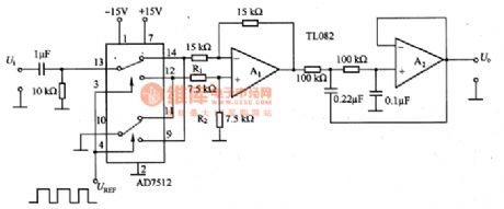
This is the synchronous wave detection circuit composed of analog switch. As the circuit is installed with an analog switch, so it can work as the wave detection circuit of the low frequency lock phase amplifier under thousands of HZ of frequency. The analog switch AD7515 shifts the basic input signal quickly, when the switch state is shown in the figure, the non-inverting input terminal of A1 is connected with the earth, the input signal is reversed; when the switch is connected with the lower terminal, the inverting phase input terminal of A1 is connected with the earth, as R1 and R2 distribute the voltage, so that A1 is turned into the amplifier which magnifying time is once.
(View)
View full Circuit Diagram | Comments | Reading(895)
TEANA A33-EL Alarm Buzzer Instruction and Circuit One
Published:2011/7/15 20:46:00 Author:Joyce | Keyword: TEANA , Alarm , Buzzer, Instruction
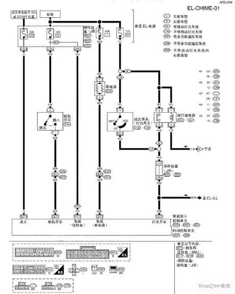
TEANA A33-EL Alarm Buzzer Instruction and Circuit (View)
View full Circuit Diagram | Comments | Reading(829)
The synchronous wave detection circuit of polarity switch
Published:2011/7/15 21:41:00 Author:Borg | Keyword: synchronous, wave detection circuit
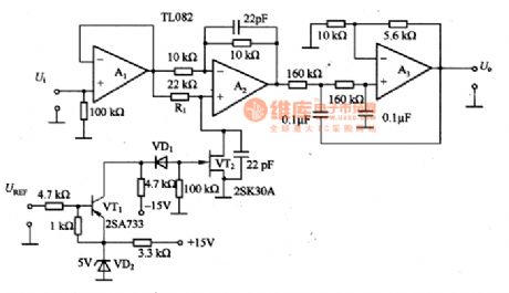
This is the synchronous wave detection circuit of polarity switch. In the circuit, the impedance switch and buffer circuit can be formed by A1; A2 forms the phase inverting and non-inverting amplifier circuit; when VT2 is conducting, the non-inverting phase of A2is connected with the ground and becomes a -1 amplifier circuit; when VT2 is blocked, the input signal is added to the non-inverting input terminal of A2, as the impedance of A2 is very high, so the inverting and non-inverting terminal have the same LEV, and the inverting terminal is moving with it, therefore, VT2 works as the follower whose magnifying time is once.
(View)
View full Circuit Diagram | Comments | Reading(873)
AN26OP AM frequency converter and FM/AM integrated circuit
Published:2011/7/17 21:56:00 Author:Borg | Keyword: frequency converter, integrated circuit
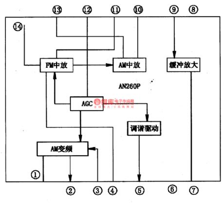
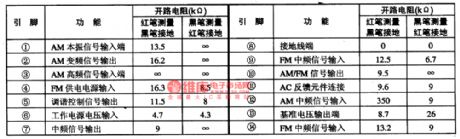
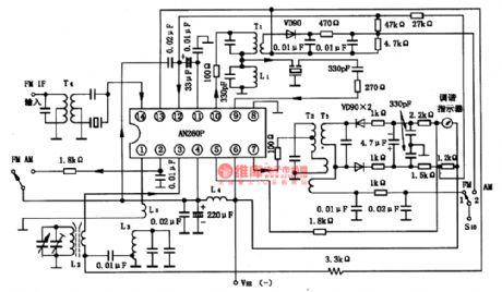
The AN260P is the AM frequency transmission, FM and AM INTREQ integrated circuit, which is used in radios, recorders and grouped stereo circuits.1. the internal circuit and pin functions of AN260PAN260P contains the tuning indication drive, voltage stabilizer, FM intermediate frequency amplifier and AGC amplifier circuit. FM and AM intermediate amplifiers are both connected with the filter.AN260P is in the 14-pin dual in-line package, whose internal circuit is in figure 1.
(View)
View full Circuit Diagram | Comments | Reading(2060)
AK4524—the digit audio signal decoding integrated circuit
Published:2011/7/17 22:04:00 Author:Borg | Keyword: signal decoding, integrated circuit
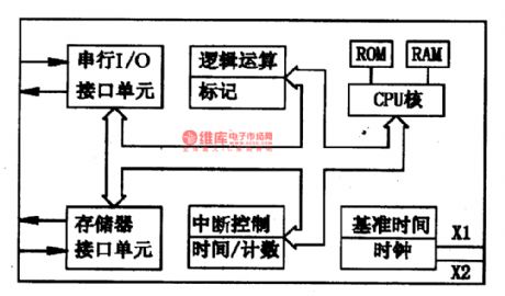
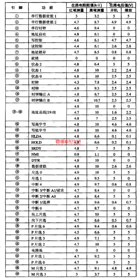
AK4524 is a digit audio signal decoding integrated circuit produced by Panasonic, which is used in Sony PIP color TV sets.\ AK4524 contains the digit audio signal decoding and D/A converter, and it is fixed with the shift circuit. When the IC is used in Sony SCC-P33DA/CA, the pin functions and data of the circuit is listed in table 1.
The AMl86ZM25KC single chip microcomputer integrated circuitAMl86ZM25KC is a 16-bit CMOS specific microcomputer integrated circuit.
(View)
View full Circuit Diagram | Comments | Reading(1207)
Active Highpass Filter Circuit
Published:2011/7/14 20:39:00 Author:Joyce | Keyword: Active, Highpass, Filter
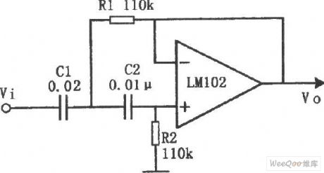
As shown in the figure is an activehigh pass filter circuit. The cut-off frequency of the circuit is: fc = 100 Hz. In this circuit, the ratio of R1 and R2, and that of C1 and C2 can be various values. R1 = R2 , C1 = 2 C2. While C1 = C2, R1 = 2 R2 is also available.
(View)
View full Circuit Diagram | Comments | Reading(695)
| Pages:1515/2234 At 2015011502150315041505150615071508150915101511151215131514151515161517151815191520Under 20 |
Circuit Categories
power supply circuit
Amplifier Circuit
Basic Circuit
LED and Light Circuit
Sensor Circuit
Signal Processing
Electrical Equipment Circuit
Control Circuit
Remote Control Circuit
A/D-D/A Converter Circuit
Audio Circuit
Measuring and Test Circuit
Communication Circuit
Computer-Related Circuit
555 Circuit
Automotive Circuit
Repairing Circuit