
Circuit Diagram
Index 1508
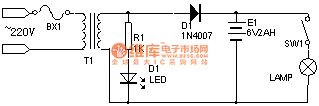
Switch type voltage stabilization nickel cadmium battery charger circuit
Published:2011/7/15 1:38:00 Author:TaoXi | Keyword: Switch type, voltage stabilization, nickel cadmium battery, charger circuit
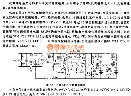
The circuit is as shown in the figure 2-6. The voltage dependent resistor RV prevents the overvoltage, the insurance resistance RT prevents the overcurrent. The blocking oscillator is composed of the switching transformer T1 and the external components. VT1 is the switching tube, the R2 and L2 windings supply the operating voltage to it, the feedback network composed of the L2 and C2. When the VT1 is conducting, the energy stores in T1; when VT1 is cutting off, the circuit outputs the energy through the L3 coupling, this energy is rectified and filted to charge the battery. Because the voltage stabilizer is working in the flyback mode, the ripple current is large, this is good for the charging. VT2 is the comparison amplifier, the voltage-regulator tube VD4 supplies the reference voltage, the voltage division circuit is composed of R5 and R6.
(View)
View full Circuit Diagram | Comments | Reading(677)
compact 15V,1A parallel regulated power supply circuit
Published:2011/7/17 7:42:00 Author:Fiona | Keyword: parallel regulated power supply
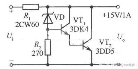
compact 15V,1A parallel regulated power supply circuit is shown as above:
(View)
View full Circuit Diagram | Comments | Reading(733)
±18V bipolar regulated power supply circuit
Published:2011/7/18 0:04:00 Author:Fiona | Keyword: bipolar regulated power supply
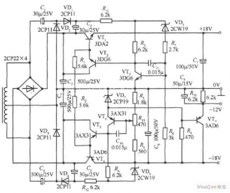
±18V bipolar regulated power supply circuit is shown as above: (View)
View full Circuit Diagram | Comments | Reading(1383)
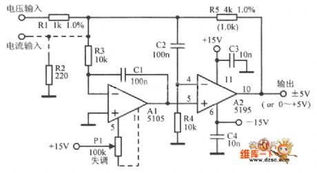
Temperature compensation logarithmic converter circuit
Published:2011/7/18 1:00:00 Author:Fiona | Keyword: Temperature compensation, logarithmic converter

Temperature compensation logarithmic converter circuit is shown as above: (View)
View full Circuit Diagram | Comments | Reading(951)
Programmable fast charging management chip MAX712/MAX713 circuit
Published:2011/7/15 0:56:00 Author:TaoXi | Keyword: Programmable, fast charging, management chip
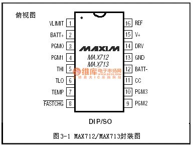
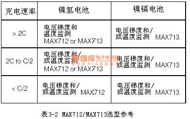
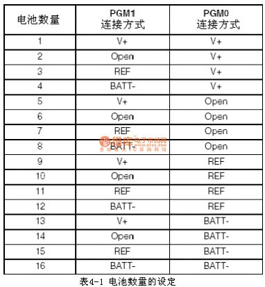
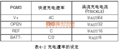
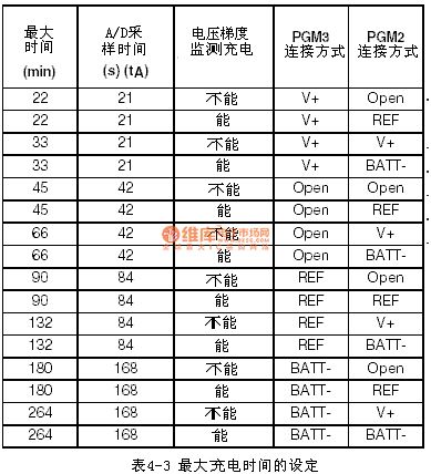
The features of MAX712 and MAX713 are very similar, the difference between them is when the MAX712 detects that the dv/dt becomes zero, it will terminate fast charging mode, but the MAX713 terminates the fast charging mode when the dv/dt becomes negative; the MAX712 and MAX713 can charge 1-16 batteries, they has the linear or switch mode power control, for the linear mode, the MAX712 and MAX713 supply the power to the load of storage battery when the storage battery is charging; they has three modes to cut off the fast charge (voltage gradient, temperature or time), and they can automaticly change from the fast charging to trickle charging; when the battery is not charging, the maximum leakage current of the storage battery is only 5mA.
(View)
View full Circuit Diagram | Comments | Reading(1268)
Relative humidity measuring instrument circuit
Published:2011/7/17 8:00:00 Author:Fiona | Keyword: Relative humidity, measuring instrument
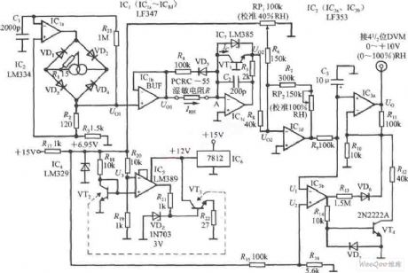
Relative humidity measuring instrument circuit is shown as above:
(View)
View full Circuit Diagram | Comments | Reading(857)
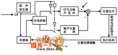
Fast converting generator circuit
Published:2011/7/18 0:54:00 Author:Fiona | Keyword: converting generator
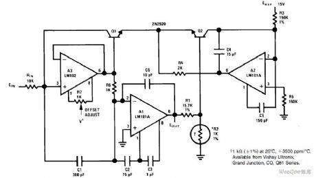
Fast converting generator circuit is shown as above:
(View)
View full Circuit Diagram | Comments | Reading(573)
Cube generator circuit
Published:2011/7/18 0:59:00 Author:Fiona | Keyword: Cube generator
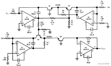
Cube generator circuit is shown as above: (View)
View full Circuit Diagram | Comments | Reading(1212)
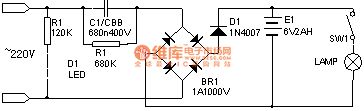
Rechargeable flashlight circuit one (3)
Published:2011/7/15 0:45:00 Author:TaoXi | Keyword: Rechargeable, flashlight
View full Circuit Diagram | Comments | Reading(866)
Rechargeable flashlight circuit one (2)
Published:2011/7/15 0:45:00 Author:TaoXi | Keyword: Rechargeable, flashlight
View full Circuit Diagram | Comments | Reading(3573)
polarity detector of absolute value amplifier circuit
Published:2011/7/17 23:50:00 Author:Fiona | Keyword: absolute value amplifier, polarity detector
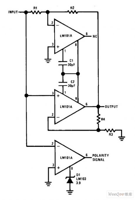
Polarity detector of absolute value amplifier circuit is shown as above:
(View)
View full Circuit Diagram | Comments | Reading(1325)
Low input current circuit that quick summary of the amplifier
Published:2011/7/17 23:01:00 Author:Fiona | Keyword: quick summary of the amplifier
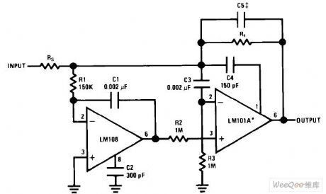
Low input current circuit that quick summary of the amplifier is shown as above: (View)
View full Circuit Diagram | Comments | Reading(822)
Telephone automatic recording control circuit
Published:2011/7/15 3:15:00 Author:Fiona | Keyword: automatic recording control
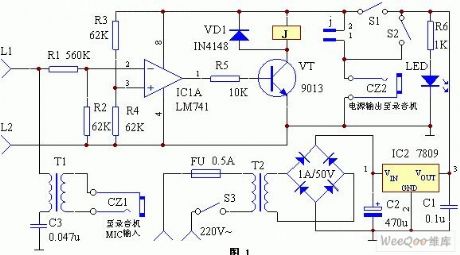
Voltage comparator which is compose of integrated circuit IC1 ( LM741) and external components is used for monitoring the telephone line voltage between L1 and L2. When the ordinary dial-up telephone is in hook state,the voltage between L1 and L2 is about 60V;when having a ringing current,it adds communication signal about 100V;when picking up the telephone receiver,the voltage between L1 and L2 drops to about 10V. Using this voltage change can judge out the telephone working state.Every time when picking up the telephone receiver,the control circuit automatically charges the recorder,then the recorder begins recording;when hanging up the telephone,the recorder automatically turns off the power to stop the recording.
(View)
View full Circuit Diagram | Comments | Reading(924)
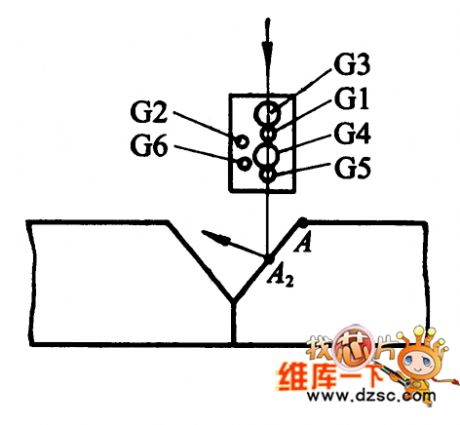
Welding Sensor Online Teaching Mode Tracking System Hardware Circuit
Published:2011/7/19 9:43:00 Author:Robert | Keyword: Welding Sensor, Online, Teaching, Tracking, System, Hardware
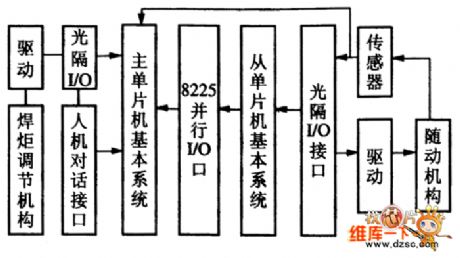
The picture shows the welding sensor online teaching mode tracking system hardware circuit. (View)
View full Circuit Diagram | Comments | Reading(814)
High-Speed Out-Phase Amplification Circuit
Published:2011/7/18 10:12:00 Author:Robert | Keyword: High-Speed, Out-Phase, Amplification
The picture shows the high-speed out-phase amplification circuit. (View)
View full Circuit Diagram | Comments | Reading(583)
Simple Shortwave Signal Amplification Circuit
Published:2011/7/18 10:17:00 Author:Robert | Keyword: Simple, Shortwave, Signal, Amplification
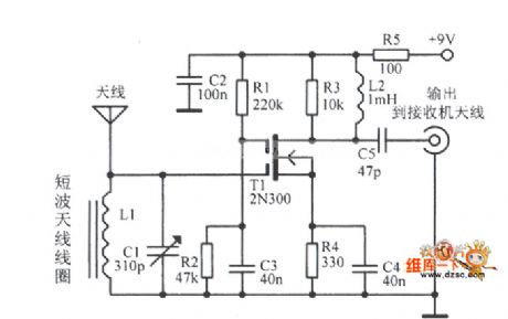
The picture shows the simple shortwave signal amplification circuit. (View)
View full Circuit Diagram | Comments | Reading(687)
Infrared Sensor Control Circuit
Published:2011/7/18 10:25:00 Author:Robert | Keyword: Infrared, Sensor, Control
The picture shows the infrared sensor control circuit. (View)
View full Circuit Diagram | Comments | Reading(899)
Six Tubes Dot Matrix Receiving Screen Circuit
Published:2011/7/19 9:23:00 Author:Robert | Keyword: Six, Tubes, Dot Matrix, Receiving, Screen
The picture shows the six tubes dot matrix receiving screen circuit. (View)
View full Circuit Diagram | Comments | Reading(534)
Transformer Grid Electrode Driving Circuit With Im Changed According To Pulse Width
Published:2011/7/18 10:23:00 Author:Robert | Keyword: Transformer, Grid Electrode, Driving, Im, Pulse Width
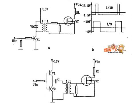
The picture shows the transformer grid electrode driving circuit with Im changed according to pulse width. (View)
View full Circuit Diagram | Comments | Reading(707)
Simple Single-Phase Full-Wave Rectifier π Type Filter Circuit
Published:2011/7/19 9:28:00 Author:Robert | Keyword: Simple, Single-Phase, Full-Wave, Rectifier, π, Filter
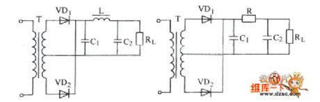
The picture shows the simple single-phase full-wave rectifier π type filter circuit. (View)
View full Circuit Diagram | Comments | Reading(696)
| Pages:1508/2234 At 2015011502150315041505150615071508150915101511151215131514151515161517151815191520Under 20 |
Circuit Categories
power supply circuit
Amplifier Circuit
Basic Circuit
LED and Light Circuit
Sensor Circuit
Signal Processing
Electrical Equipment Circuit
Control Circuit
Remote Control Circuit
A/D-D/A Converter Circuit
Audio Circuit
Measuring and Test Circuit
Communication Circuit
Computer-Related Circuit
555 Circuit
Automotive Circuit
Repairing Circuit