
Circuit Diagram
Index 1521
W1525A control circuit, main features and pin of DC-DC circuit and power supply monitor
Published:2011/7/11 6:02:00 Author:Lucas | Keyword: control circuit , main features , pin , DC-DC circuit , power supply monitor
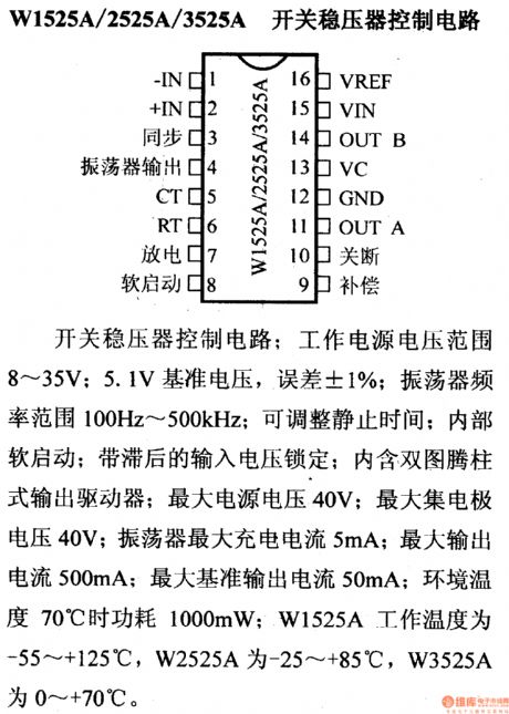
W1525A/2525A/3525A switching regulatorcontrol circuit
Operating supply voltage range is 8 ~ 35V; it has 5.1V reference voltage; error is ± 1%; oscillator frequency range is 100Hz ~ 500kHz; it has adjustable stationary time and internal soft-start and hysteretic input voltage lockout; it contains dual totem pole output drivers; the maximum supply voltage is 40V; the maximum collector voltage is 40V; the maximum charge current of oscillator is 5mA; the maximum output current is 500mA; the maximum reference output current is 50mA; when ambient temperature is 70 ℃, the power consumption is 1000mW; W1525A operating temperature is -55 ~ +125 ℃, and W2525A is -25 ~ +85 ℃, and W3525A is 0 ~ +70 ℃.
(View)
View full Circuit Diagram | Comments | Reading(708)
TL594 switching regulator, main features and pin of DC-DC circuit and power supply monitor
Published:2011/7/11 5:53:00 Author:Lucas | Keyword: switching regulator, main features , pin , DC-DC circuit , power supply monitor
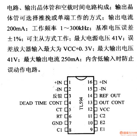
It is composed of the 5V reference voltage, oscillator, error amplifier, comparator, flip-flop, output control circuit, output transistor and load time circuit; output transistor can select single-end or push-pull working way; output current is 200mA; frequency is 1 ~ 300KHz; reference voltage is ± 1%; be the main way to work from; maximum supply voltage of 41V; error amplifier input can be up to VCC +0.3 V; the maximum output voltage is 41V; maximum output current is 250mA.
(View)
View full Circuit Diagram | Comments | Reading(1074)
DC-DC Optoelectronic Isolator Circuit
Published:2011/7/11 23:57:00 Author:Michel | Keyword: Optoelectronic Isolator Circuit
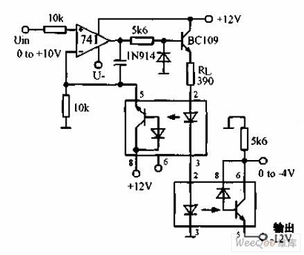
The above picture is DC-DC optoelectronic isolator circuit.The circuit is used to produce input isolation for silicon controlled converter. The above photoelectric isolator constitutes a negative feedback for the op-amp and the following photoelectric isolator completes the photoelectric signal transmission.And transmission nonlinear is within 2%.
(View)
View full Circuit Diagram | Comments | Reading(1435)
0-10 Minutes Timer Circuit with One Second Accuracy
Published:2011/7/12 2:28:00 Author:Michel | Keyword: Timer Circuit
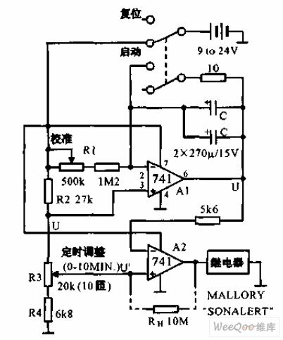

The 0-10 minutes timer circuit with one second accuracy is shown as above.It uses resistors and capacitances etc. to constitute one second accuracy timer. After it is calibrating,its accuracy has nothing to do with power voltage.Because the power supply voltage influences the charging voltage and the threshold voltage of the comparator meanwhile.The timer's delay time is CR1R3/R2. (View)
View full Circuit Diagram | Comments | Reading(810)
The Low Consumption Timer Circuit
Published:2011/7/12 2:53:00 Author:Michel | Keyword: Timer Circuit
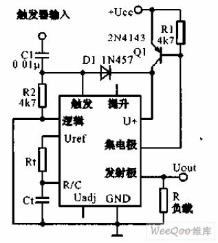
The low consumption timer uses timer IC LM122 and it provides the zero power consumption circuit in two rated cycles.The transistor Q1 stops between the two rated cycles so there is no current consumption.When 5 V or higher triggering pulse arrives and Q1 is connected and it begins to measure time. Timing time is set by the R1 and C1, its range is from a few microseconds to several hours. (View)
View full Circuit Diagram | Comments | Reading(798)
0-5 Minutes Delay Circuit of Power Frequency
Published:2011/7/14 23:39:00 Author:Michel | Keyword: Power Frequency, Delay Circuit
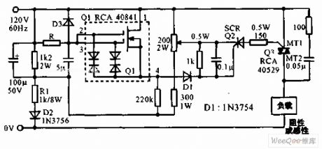
Power frequency 0-5 minutes delay circuit is shown as the above picture.This circuit uses double grid mosfet RCA40841 to constitute controlled silicon trigger circuit and the R value determines the delay time.When R is 60MΩ(LRC type CGH type resistor) and the relay time is 5 minutes and bidirectional controlled silicon can drive large current resistance loading or electrical resistance AC loading.And the error is within 10% if it is in -25~+60℃. (View)
View full Circuit Diagram | Comments | Reading(951)
HJ94015 Christmas tree music lights control circuit
Published:2011/7/18 5:53:00 Author:Lucas | Keyword: Christmas tree , music lights , control circuit
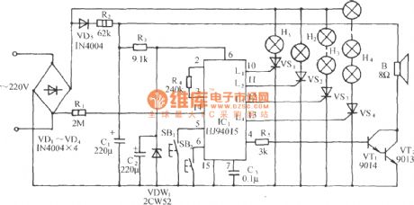
The circuit is shown as the chart. It is composed of the integrated circuit HJ94015 with simple circuit, good audio and video effect. HJ94015 is integrated circuit which is designed specifically for the Christmas tree with DIP-16 plastic structure. It has stored 16 electronic musics, and there are eight modes including full string lights, string lights, string valley lights and different songs singing in a row and so on.
(View)
View full Circuit Diagram | Comments | Reading(2941)
Electronic locust killer device 2
Published:2011/7/17 19:06:00 Author:Lucas | Keyword: Electronic locust killer
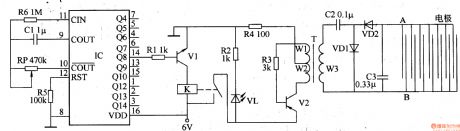
The electronic locust killer device is composed of the square wave oscillator circuit and high-voltage generator circuit, and the cirucuit is shown in Figure 3-192. Square-wave oscillator is composed of the counting divider lC and resistors R5, R6, capacitor Cl and potentiometer RP. High-voltage generator is composed of the transistors VI, V2, the relay K, resistors Rl-R4, light-emitting diode VL, step-up transformer T, capacitors C2, C3 and diodes VDl, VD2. Rl-R6 use 1/4W carbon film resistors or metal film resistors. RP uses the organic solid variable resistor. Cl selects the monolithic capacitor.
(View)
View full Circuit Diagram | Comments | Reading(2511)
Electronic locust killer device 1
Published:2011/7/17 19:13:00 Author:Lucas | Keyword: Electronic locust killer
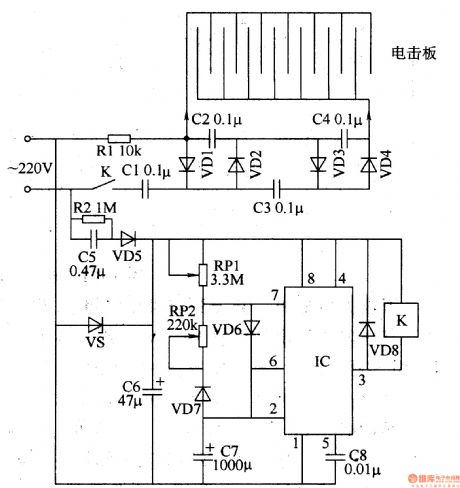
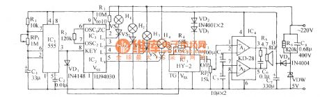
The electronic locust killer device is composed of the power supply circuit, self-excited oscillator and high-voltage generating circuit, and the cirucuit is shown in Figure 3-191. Power supply circuit consists of resistor R2, step-down capacitor C5, rectifier diode VD5, voltage regulator diode VS and filter capacitor C6. The self-excited oscillator circuit is composed of the time-base integrated circuit IC and potentiometers RPI, RP2, diodes VD6-VD8, capacitors C7, C8. High-voltage generating circuit consists of resistor Rl, doubler rectifier circuit composed of capacitors Cl-C4 and rectifier diodes VDl-VD4, and plate electrode. Rl and R2 select 1/2W metal film resistors. RPl and RP2 use the sealed miniature potentiometers or variable resistors.
(View)
View full Circuit Diagram | Comments | Reading(876)
The Input Loop Circuit of Amplifier Circuit
Published:2011/7/15 2:24:00 Author:Michel | Keyword: Input Loop Circuit
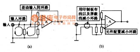
The picture (a) is the loop composed of one circle coils of the op-amp amplifier circuit input end.The magnetic will feel the electric potential when it flows through the loop and there will be noise in op-amp output part.Therefore, we need to pay attention to the components configuration and wiring,anti-noise ability can be strengthen by reducing the area of the loop, and it is shown as figure (b). (View)
View full Circuit Diagram | Comments | Reading(793)
Ultrasonic atomizer 2
Published:2011/7/17 19:25:00 Author:Lucas | Keyword: Ultrasonic atomizer
The ultrasonic atomizer circuit is composed of the power supply circuit, control circuit, water detection alarm circuit and ultrasonic oscillator, and the cirucuit is shown in Figure 3-190. Power supply circuit is composed of the power switch S, fuses FUl, FU2, timer Q, power transformer T, bridge rectifier UR, resistors Rl, R2, transistors Vl, voltage regulator diode VS, capacitors Cl, C2, and power indicator LED VL. Control circuit consists of resistor R3, capacitors C3, C4 and relays Kl, K2. Water detection and alarm circuit consists of reed switch, time-base IC rC, resistors R5-R7, capacitors C5, ClO, and buzzer HA.
(View)
View full Circuit Diagram | Comments | Reading(3572)
Ultrasonic atomizer 1
Published:2011/7/17 19:28:00 Author:Lucas | Keyword: Ultrasonic atomizer
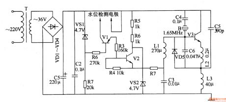
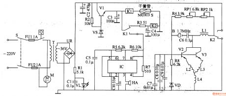
The ultrasonic atomizer circuit is composed of the power supply circuit, oscillator circuit and the water level control circuit, and the cirucuit is shown in Figure 3-189. Power supply circuit is composed of the power transformer T, rectifier diodes VDl-VD4, filter capacitors Cl, C2, zener diode VSl and resistor Rl. Water level detection control circuit consists of two electrodes, transistors Vl, V2, resistors R2-R7 and Zener diode VS2. Oscillator circuit consists of transistor V3, capacitors C3-C6, inductors Ll-L3 and the crystal ultrasonic transducer B. Rl-R7 select the 1/4W carbon film resistors or metal film resistors.
(View)
View full Circuit Diagram | Comments | Reading(5061)
Power Input Conversion Thick Membrane Integrated Circuit of STR80145 and STR80145A
Published:2011/7/15 4:14:00 Author:Michel | Keyword: Power Input Conversion, Thick Membrane Integrated Circuit
STR80145 and STR80145A are power input conversion thick membrane integrated circuits of SANKEN and they are used in various big screen color TVs.
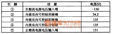
First,Functions and Features STR80145 and STR80145A integrated circuits contain controlled silicon, the power supply voltage sampling circuit, double voltage and bridge rectifying power supply switch circuits etc.
Second,Pins and DataThe pins functions and data of STR80145 and STR80145A are shown as table 1.
Table 1:Pins Functions and Data of STR80145 and STR80145A (View)
View full Circuit Diagram | Comments | Reading(926)
Technique Parameters Circuit of Toyota Land Cruiser (LANDCRUISER70) Light Off-road Vehicle
Published:2011/7/15 0:13:00 Author:Michel | Keyword: Toyota, Light Off-road Vehicle, Technique Parameters Circuit
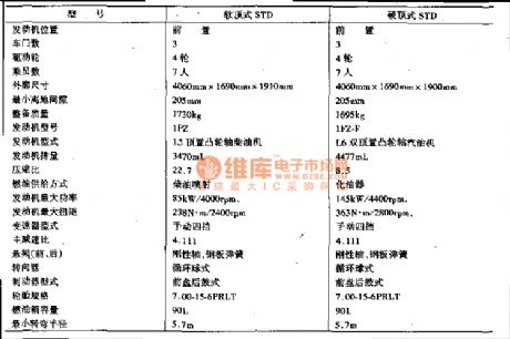
There are many Toyota land cruiser (LANDCRUISER70) light off-rood vehicles in China.They are widely used in in forest, desert, oil field, microwave station and state-owned farms, and other departments and they are praised by users,which is same with land cruiser FJ6O,BJ40、43,HJ47 off-road vehicles which are imported to China in the 1980S.
70 light off-rood vehicle can equip many kinds of engines such as 22 RE type gas injection engine,22R type carburetor type gas engine and lFZ-F type carburetor type gasoline engine.It can be installed with lPZ type diesel engine and engine emission is from 360 OmL-450 OmL. (View)
View full Circuit Diagram | Comments | Reading(495)
HJ94030 wonderful multi-song string lights automatic control circuit
Published:2011/7/18 6:00:00 Author:Lucas | Keyword: wonderful multi-song , string lights , automatic control circuit
In the circuit shown as the chart, it includes the beat pulse generator, lights control circuit, songs sound circuit, audio amplifier and power supply step-down circuit. In the figure, HJ94030 is a versatile light string control ASIC.
(View)
View full Circuit Diagram | Comments | Reading(656)
The typical application circuit of HJ94030 multi-function light control IC
Published:2011/7/18 5:57:00 Author:Lucas | Keyword: typical application, multi-function , light control IC
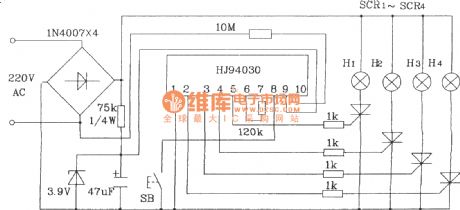
In the Figure, the button SB is used to select lights string H1 ~ H4 flashing mode, and each pressing time will change a pattern. Chip power is supplied by 220V AC and rectified by the regulator and resistor. It is a simple circuit without debugging
(View)
View full Circuit Diagram | Comments | Reading(801)
The typical application circuit of HJ94015 Christmas lights string control IC
Published:2011/7/18 19:05:00 Author:Lucas | Keyword: typical application circuit , Christmas lights , string control IC

In the Figure, Sis the working modeselection button, and SB2 is used to select piezoelectric ceramics B sound volume and light string's cycle speed.
(View)
View full Circuit Diagram | Comments | Reading(2237)
HT7713 Touching stepping dimming light circuit
Published:2011/7/18 19:08:00 Author:Lucas | Keyword: Touching , stepping , dimming light circuit
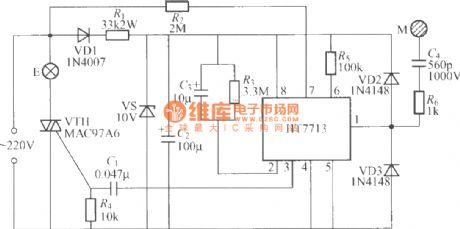
The chart shows the touching stepping dimming light circuit which is composed of HT7713, when you use it, as long as totouch M, light brightness is changed by the cycle of low light, the light, light, off, low light ... .
(View)
View full Circuit Diagram | Comments | Reading(852)
HT7704 Touching stepping dimming light circuit
Published:2011/7/18 19:13:00 Author:Lucas | Keyword: Touching stepping , dimming light circuit
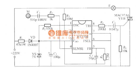
The touching stepping dimming light circuit shown aschartis composed of HT7704 integrated circuit, andHT7704 is a series of products, which has HT7704A, HT7704B and HT7704C. HT7704A is the three-step touch dimmer, and HT7704Bis the four-step touch dimmer, thenHT7704C is the two-step dimmer, that is touching on / off control, and these three application circuits arethe same.
(View)
View full Circuit Diagram | Comments | Reading(1348)
HT7700 touching stepless dimmer circuit
Published:2011/7/18 19:17:00 Author:Lucas | Keyword: touching stepless dimmer
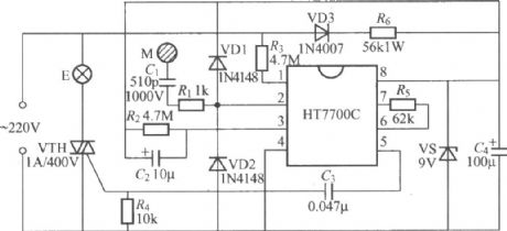
The touching stepless dimmer circuit shown as the chart is composed of HT7700 specific integrated circuit produced by Taiwan Hetai (HOLTEK). It can do stepless continuous light dimming by touching the electrodes M, in fact, the brightness of the light is changed by 96 steps.
(View)
View full Circuit Diagram | Comments | Reading(1927)
| Pages:1521/2234 At 2015211522152315241525152615271528152915301531153215331534153515361537153815391540Under 20 |
Circuit Categories
power supply circuit
Amplifier Circuit
Basic Circuit
LED and Light Circuit
Sensor Circuit
Signal Processing
Electrical Equipment Circuit
Control Circuit
Remote Control Circuit
A/D-D/A Converter Circuit
Audio Circuit
Measuring and Test Circuit
Communication Circuit
Computer-Related Circuit
555 Circuit
Automotive Circuit
Repairing Circuit