
Circuit Diagram
Index 1529
Ringing switching power supply practical circuit
Published:2011/7/15 22:44:00 Author:Christina | Keyword: Ringing, switching power supply, practical circuit
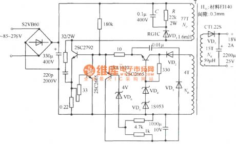
The ringing switching power supply practical circuit is as shown in the figure. The primary winding Np of the transformer is connected with the diode VD, the resistance R and capacitance C, the purpose of this connection method is to release the power of the transformer leakage inductance. That is during the conduction of the switching tube, the current accumulates the power on the leakage inductance, but this power is not transfered to the secondary stage of the transformer as the electric power. So it produces the reverse emf when the switching tube is cutting off, there is the high surge voltage to puncture the switching tube.
(View)
View full Circuit Diagram | Comments | Reading(1075)
Monitoring Other Voltage Circuit
Published:2011/7/16 21:14:00 Author:Robert | Keyword: Monitoring, Voltage
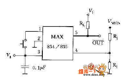
The picture shows the monitoring other voltage circuit. (View)
View full Circuit Diagram | Comments | Reading(904)
Monitoring 5V Voltage Circuit Composed Of NJM2103
Published:2011/7/16 21:20:00 Author:Robert | Keyword: Monitoring, 5V, Voltage
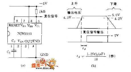
The picture shows the monitoring 5V voltage circuit composed of NJM2103. (View)
View full Circuit Diagram | Comments | Reading(1115)
-500~0V High-Power Operational Amplifier Circuit
Published:2011/7/17 1:34:00 Author:Robert | Keyword: High-Power, Operational Amplifier
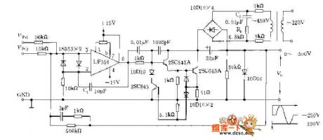
The picture shows the -500~0V high-power operational amplifier circuit. (View)
View full Circuit Diagram | Comments | Reading(616)
Single-Phase Electronic Prepaid Watt-Hour Meter Design Circuit
Published:2011/7/17 7:47:00 Author:Robert | Keyword: Single-Phase, Electronic, Prepaid, Watt-Hour Meter, Design
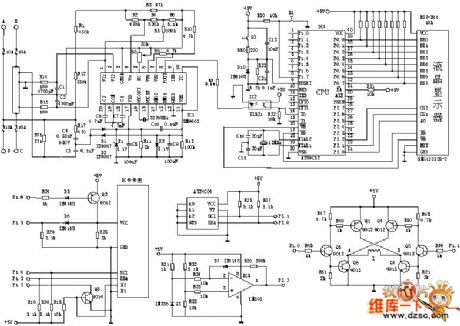
The picture shows the single-phase electronic prepaid watt-hour meter design circuit. (View)
View full Circuit Diagram | Comments | Reading(1843)
Daily Work Transaction Processing Flow Diagram Circuit
Published:2011/7/16 21:30:00 Author:Robert | Keyword: Daily Work, Transaction, Processing, Flow Diagram
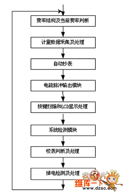
The picture shows the daily work transaction processing flow diagram circuit. (View)
View full Circuit Diagram | Comments | Reading(713)
Clock Circuit Main Program Flow Diagram Circuit
Published:2011/7/16 21:22:00 Author:Robert | Keyword: Clock, Program, Flow Diagram
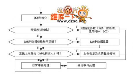
The picture shows the clock circuit main program flow diagram circuit. (View)
View full Circuit Diagram | Comments | Reading(697)
RTC-4553 Pin And Its Peripheral Circuit
Published:2011/7/16 21:27:00 Author:Robert | Keyword: Pin, Peripheral
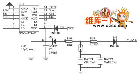
The picture shows the RTC-4553 pin and its peripheral circuit. (View)
View full Circuit Diagram | Comments | Reading(770)
Over-Voltage Alarming Circuit By Using LT1073
Published:2011/7/16 9:13:00 Author:Robert | Keyword: Over-Voltage, Alarming
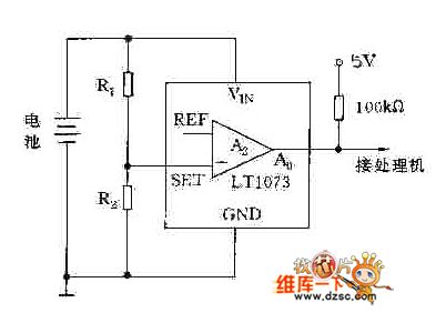
The picture shows the over-voltage alarming circuit by using LT1073. (View)
View full Circuit Diagram | Comments | Reading(560)
SA9904 Pin And Peripheral Circuit
Published:2011/7/16 9:03:00 Author:Robert | Keyword: Pin, Peripheral
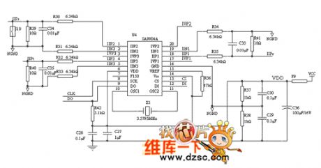
The picture shows the SA9904 pin and peripheral circuit. (View)
View full Circuit Diagram | Comments | Reading(847)
Communication Serial Port Multiplexing Circuit
Published:2011/7/16 21:26:00 Author:Robert | Keyword: Communication, Serial, Port, Multiplexing

The picture shows the communication serial port multiplexing circuit. (View)
View full Circuit Diagram | Comments | Reading(809)
Multifunctional Energy Meter Overall Structure Circuit
Published:2011/7/17 7:10:00 Author:Robert | Keyword: Multifunctional, Energy, Meter, Overall, Structure
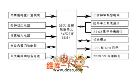
The picture shows the multifunctional energy meter overall structure circuit. (View)
View full Circuit Diagram | Comments | Reading(522)
Driving Circuit By Using Speed-Up Capacitor
Published:2011/7/16 9:32:00 Author:Robert | Keyword: Driving, Speed-Up Capacitor
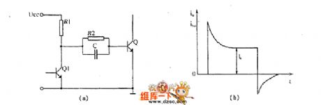
The picture shows the driving circuit by using speed-up capacitor. (View)
View full Circuit Diagram | Comments | Reading(1971)
500 Type Multimeter Circuit Principle Instrumetation Circuit
Published:2011/7/16 10:15:00 Author:Robert | Keyword: Multimeter, Principle, Instrumetation
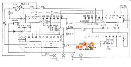
The picture shows the 500 type multimeter circuit principle instrumetation circuit. (View)
View full Circuit Diagram | Comments | Reading(1542)
One Normal Type Driving Circuit
Published:2011/7/16 9:08:00 Author:Robert | Keyword: Normal, Driving
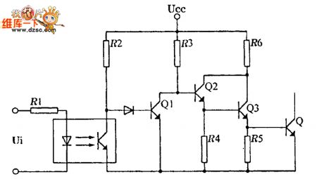
The picture shows the one normal type driving circuit. (View)
View full Circuit Diagram | Comments | Reading(600)
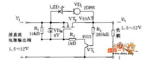
Ringing switch power supply over-current protection circuit
Published:2011/7/15 22:32:00 Author:Christina | Keyword: Ringing switch, power supply, over-current, protection circuit
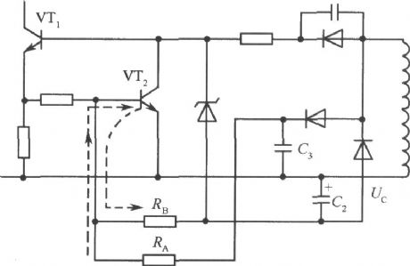
In the ringing current-limit switching power supply, the output current Io has no corresponding relationship with the primary stage current Ic. For the same collector electrode current Ic, with the rise of the input voltage, the Io will increase too. So in the ringing type switching circuit, in addition to use the start protection measures, we also need to set the protection circuit which is as shown in the figure. We add the RA and RB on the base subcircuit of VT2. Because the voltage of C3 is the positive polarity voltage which is proportional to the input voltage, so if the input voltage Vi rises, the current which flows through the resistance RA will increase to accelerate the conduction of VT2.
(View)
View full Circuit Diagram | Comments | Reading(651)
Brushless DC Motor Driving Circuit
Published:2011/7/17 7:12:00 Author:Robert | Keyword: Brushless, DC, Motor, Driving
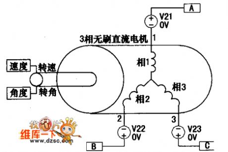
The brushless DC motor driving circuit is shown in the picture. (View)
View full Circuit Diagram | Comments | Reading(1180)
Power Rectifier Protector Circuit
Published:2011/7/17 7:15:00 Author:Robert | Keyword: Power, Rectifier, Protector
The picture shows the power rectifier protector circuit. (View)
View full Circuit Diagram | Comments | Reading(550)
Over-Voltage Adjustable Protection Circuit
Published:2011/7/16 9:41:00 Author:Robert | Keyword: Over-Voltage, Adjustable, Protection

The picture shows the over-voltage adjustable circuit. (View)
View full Circuit Diagram | Comments | Reading(609)
Simple And Reliable Commercial Power Over-Voltage Protector Circuit
Published:2011/7/17 8:07:00 Author:Robert | Keyword: Simple, Reliable, Commercial Power, Over-Voltage, Protector
The picture shows the simple and reliable commercial power over-voltage protector circuit. (View)
View full Circuit Diagram | Comments | Reading(671)
| Pages:1529/2234 At 2015211522152315241525152615271528152915301531153215331534153515361537153815391540Under 20 |
Circuit Categories
power supply circuit
Amplifier Circuit
Basic Circuit
LED and Light Circuit
Sensor Circuit
Signal Processing
Electrical Equipment Circuit
Control Circuit
Remote Control Circuit
A/D-D/A Converter Circuit
Audio Circuit
Measuring and Test Circuit
Communication Circuit
Computer-Related Circuit
555 Circuit
Automotive Circuit
Repairing Circuit