
Circuit Diagram
Index 1530
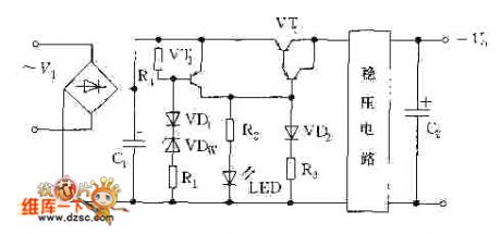
Stabilized Voltage Supply Adding Additional Over-Voltage Protection Circuit
Published:2011/7/17 8:10:00 Author:Robert | Keyword: Stabilized Voltage Supply, Over-Voltage, Protection
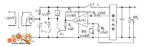
The picture shows the stabilized voltage supply adding additional over-voltage protection circuit. (View)
View full Circuit Diagram | Comments | Reading(551)
The method to change the output voltage of the ringing switch power supply
Published:2011/7/15 22:22:00 Author:Christina | Keyword: method, output voltage, ringing switch, power supply
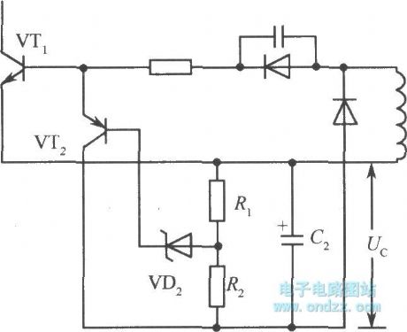
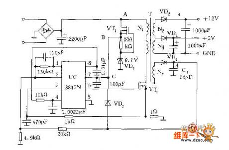
In the simple ringing current-limit type switching voltage stabilization circuit, the output voltage Vo is proportional to the negative bias Uc. If you want to change the output voltage, you need to change the Uc, as shown in the figure.
The collector electrode of the transistor VT2 is connected with the negative terminal of the capacitor C2. Once the Uc2 rises, the current which flows through the zener diode VD2 and the transistor VT2 will increase to conduct VT2. Because the collector electrode current of VT2 shortens the conduction time of the switching transistor VT1, so we can cut off the circuit in advance to reduce the output voltage Vo. (View)
View full Circuit Diagram | Comments | Reading(696)
Over-Voltage Protection Circuit By Using The Principle Of Over-Heat Generated By Over-Voltage
Published:2011/7/17 8:04:00 Author:Robert | Keyword: Over-Voltage, Protection, Principle, Over-Heat
The pictrue shows the over-voltage protection circuit by using the principle of over-heat generated by over-voltage. (View)
View full Circuit Diagram | Comments | Reading(609)
Over-Voltage Protection Circuit Composed Of Fuse And Thyristor
Published:2011/7/17 9:42:00 Author:Robert | Keyword: Over-Voltage, Protection, Fuse, Thyristor
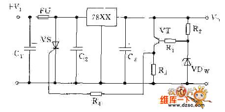
The picture shows the over-voltage protection circuit composed of fuse and thyristor. (View)
View full Circuit Diagram | Comments | Reading(792)
Over-Voltage Protection Circuit Composed Of Transistors
Published:2011/7/16 9:47:00 Author:Robert | Keyword: Over-Voltage, Protection, Transistor
The picture shows the over-voltage protection circuit composed of transistors. (View)
View full Circuit Diagram | Comments | Reading(670)
Over-Voltage Protection Circuit Composed Of Transistor And Relay (2)
Published:2011/7/16 9:55:00 Author:Robert | Keyword: Over-Voltage, Protection, Transistor, Relay

The picture shows the over-voltage protection circuit composed of transistor and relay (2). (View)
View full Circuit Diagram | Comments | Reading(644)
Over-Voltage Protection Circuit Composed Of Transistor And Relay (1)
Published:2011/7/16 9:52:00 Author:Robert | Keyword: Over-Voltage, Protection, Transistor, Relay
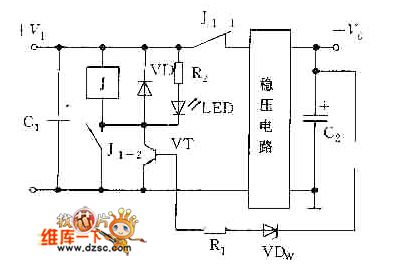
The picture shows the over-voltage protection circuit composed of transistor and relay (1). (View)
View full Circuit Diagram | Comments | Reading(670)
Starting Circuit By Using FET
Published:2011/7/17 9:46:00 Author:Robert | Keyword: Starting, FET
The picture shows the starting circuit by using FET. (View)
View full Circuit Diagram | Comments | Reading(591)
Battery Protection Circuit
Published:2011/7/16 10:03:00 Author:Robert | Keyword: Battery, Protection
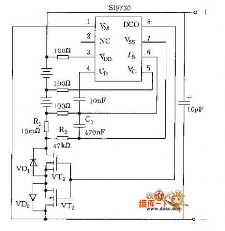
The picture shows the battery protection circuit. (View)
View full Circuit Diagram | Comments | Reading(829)
Practical Under-Voltage And Over-Voltage Protection Circuit
Published:2011/7/17 8:01:00 Author:Robert | Keyword: Practical, Under-Voltage, Over-Voltage, Protection
The picture shows the practical under-voltage and over-voltage protection circuit. (View)
View full Circuit Diagram | Comments | Reading(2496)
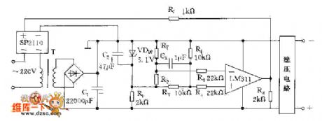
Power Over-Voltage Protection Circuit By Using μPC3423
Published:2011/7/17 8:18:00 Author:Robert | Keyword: Power, Over-Voltage, Protection
The picture shows the power over-voltage protection circuit by using μPC3423. (View)
View full Circuit Diagram | Comments | Reading(634)
I/O Interface And Static Switch Driving Circuit
Published:2011/7/17 8:13:00 Author:Robert | Keyword: I/O, Interface, Static, Switch, Driving
The picture shows the I/O interface and static switch driving circuit. (View)
View full Circuit Diagram | Comments | Reading(525)
Electronic Switch And Driving Circuit
Published:2011/7/17 8:14:00 Author:Robert | Keyword: Electronic, Switch, Driving
The picture shows the electronic switch and driving circuit. (View)
View full Circuit Diagram | Comments | Reading(655)
Dual polarity voltage stabilizer with the three-port voltage stabilizer
Published:2011/7/16 5:52:00 Author:Christina | Keyword: Dual polarity, voltage stabilizer, three-port, voltage stabilizer
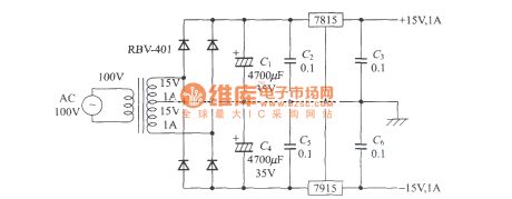
View full Circuit Diagram | Comments | Reading(665)
Sensor Structure Circuit
Published:2011/7/17 9:48:00 Author:Robert | Keyword: Sensor, Structure
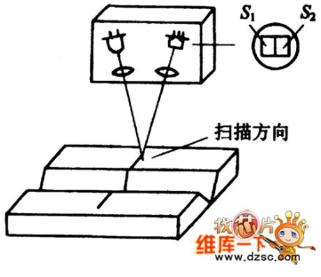
The picture shows the sensor structure circuit. (View)
View full Circuit Diagram | Comments | Reading(554)
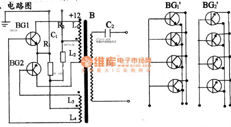
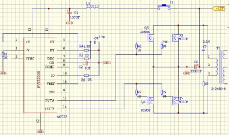
The inverter circuit 14
Published:2011/7/16 4:26:00 Author:Christina | Keyword: inverter
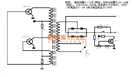
Data: base coil 8-10 turns (two groups), Primary coil 18-24 turns (two groups), Subprime coil600-800 turns, the high power relay. The 39 and 2.7ohms resistabce is 2-4W; the 6uF capacitance's voltage is 1000V.
(View)
View full Circuit Diagram | Comments | Reading(762)
The inverter circuit 13
Published:2011/7/16 4:22:00 Author:Christina | Keyword: inverter
View full Circuit Diagram | Comments | Reading(917)
The inverter circuit 12
Published:2011/7/16 4:18:00 Author:Christina | Keyword: inverter

View full Circuit Diagram | Comments | Reading(880)
The inverter circuit 11
Published:2011/7/16 4:18:00 Author:Christina | Keyword: inverter
View full Circuit Diagram | Comments | Reading(2457)
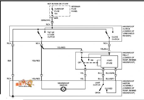
Mazda 96PROBE electrical ceiling circuit diagram
Published:2011/7/16 22:44:00 Author:nelly | Keyword: Mazda, electrical ceiling
View full Circuit Diagram | Comments | Reading(476)
| Pages:1530/2234 At 2015211522152315241525152615271528152915301531153215331534153515361537153815391540Under 20 |
Circuit Categories
power supply circuit
Amplifier Circuit
Basic Circuit
LED and Light Circuit
Sensor Circuit
Signal Processing
Electrical Equipment Circuit
Control Circuit
Remote Control Circuit
A/D-D/A Converter Circuit
Audio Circuit
Measuring and Test Circuit
Communication Circuit
Computer-Related Circuit
555 Circuit
Automotive Circuit
Repairing Circuit