
Circuit Diagram
Index 1532
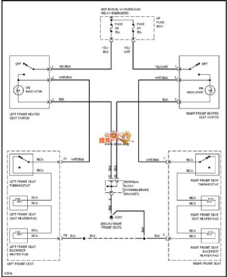
96 VOLVO 960 seat heating circuit diagram
Published:2011/7/17 0:11:00 Author:nelly | Keyword: VOLVO, seat heating
View full Circuit Diagram | Comments | Reading(572)
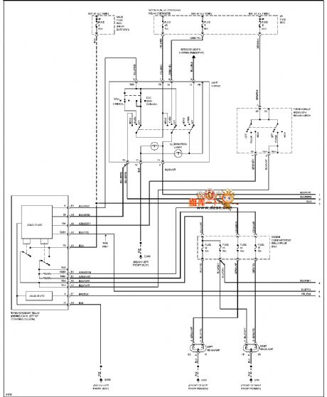
96 VOLVO 960 hedlight and fog lamp circuit diagram
Published:2011/7/17 0:12:00 Author:nelly | Keyword: VOLVO, hedlight, fog lamp
View full Circuit Diagram | Comments | Reading(575)
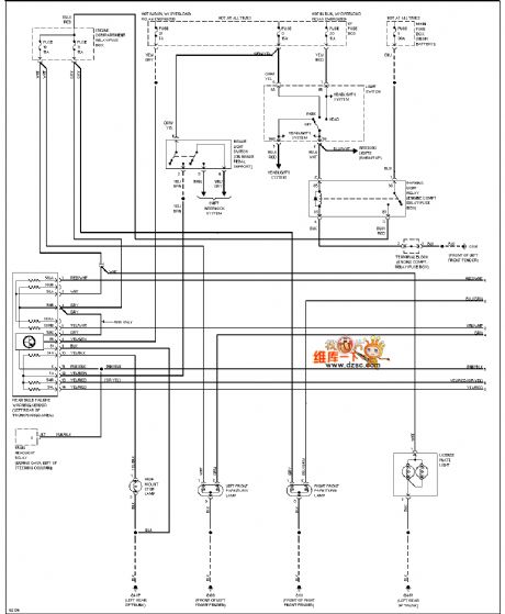
96 VOLVO 960 external lamp circuit diagram(station wagon)
Published:2011/7/17 0:13:00 Author:nelly | Keyword: VOLVO, external lamp, station wagon
View full Circuit Diagram | Comments | Reading(525)
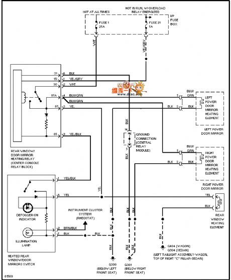
96 VOLVO 960 demister circuit diagram
Published:2011/7/17 0:14:00 Author:nelly | Keyword: VOLVO, demister
View full Circuit Diagram | Comments | Reading(476)
MC3367 (communication equipment) FM receiver circuit
Published:2011/7/15 22:11:00 Author:Christina | Keyword: communication equipment, FM, receiver
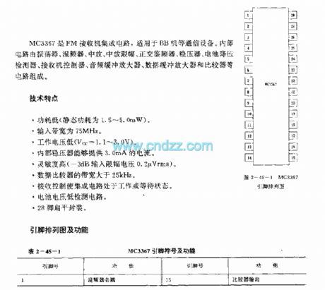
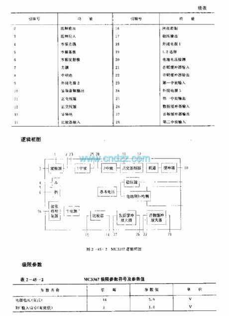
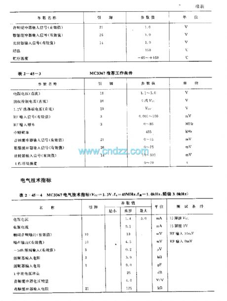
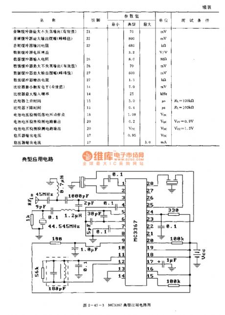
The MC3367 is designed as one kind of FM receiver circuit that can be used in the communication equipments such as the BB machine. The internal circuit is composed of the oscillator, the mixer, the intermediate frequency amplifier, the intermediate frequency amplitude limiting device, the quadrature discriminator, the voltage stabilizer, the battery step-down detector, the receiver controller, the audio buffer amplifier, the data buffer amplifier and the comparator circuits.
Features
Low power consumption (the static power consumption is 1.5-5.0mW);The input bandwidth is 75 MHz;The operating voltage is low, Vcc=1.1-3.0V;The internal voltage stabilizer supplies the 3.0mA current;High sensitivity;The bandwidth of the data comparison is higher than 25kHz;The receiving control makes the integrated circuit in the operating or waiting state;Low battery voltage detection circuit;28-pin Flat package.
(View)
View full Circuit Diagram | Comments | Reading(1261)
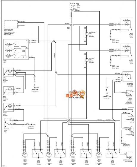
96 VOLVO 960 CTSY Courtesy circuit diagram
Published:2011/7/17 0:29:00 Author:nelly | Keyword: VOLVO, CTSY Courtesy
View full Circuit Diagram | Comments | Reading(516)
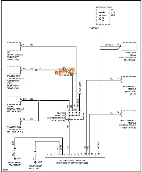
96 VOLVO 960 computer data line diagram
Published:2011/7/17 0:31:00 Author:nelly | Keyword: VOLVO, computer data line
View full Circuit Diagram | Comments | Reading(734)
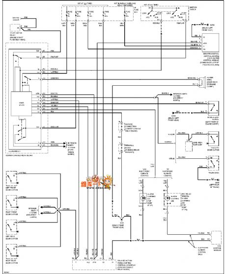
96 VOLVO 960 guard against theft line diagram
Published:2011/7/17 0:34:00 Author:nelly | Keyword: VOLVO, guard against theft
View full Circuit Diagram | Comments | Reading(647)
MC9482 (electronic toy) remote control receiving decoder circuit
Published:2011/7/17 5:46:00 Author:Christina | Keyword: electronic toy, remote control, receiving, decoder
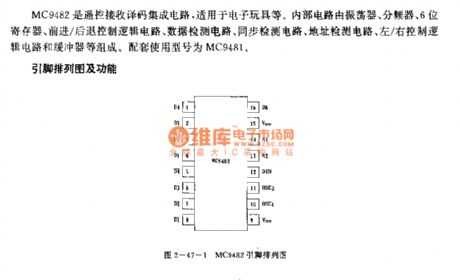
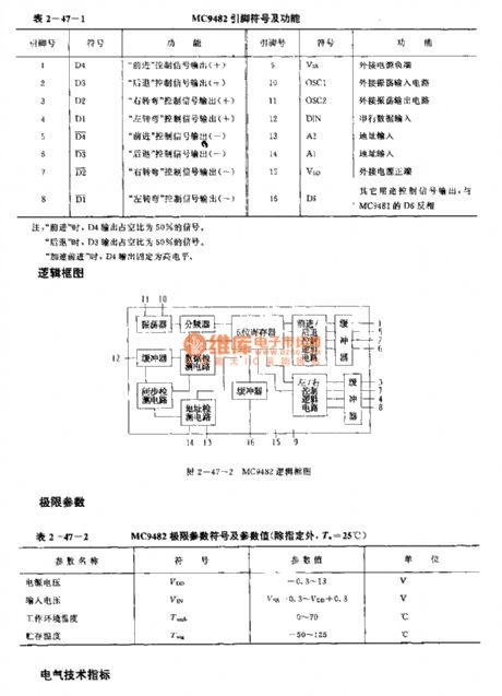
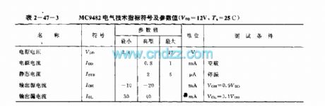
The MC9482 is designed as one kind of remote control receiving decoder circuit that can be used in the electronic toys. The internal circuit is composed of the oscillator, the frequency divider, the 6-bit register, the forward/back control logic circuit, the data detection circuit, the synchronous detection circuit, the address detection circuit, the left/right control logic circuit and the buffer. The matching model is MC9481.
(View)
View full Circuit Diagram | Comments | Reading(1193)
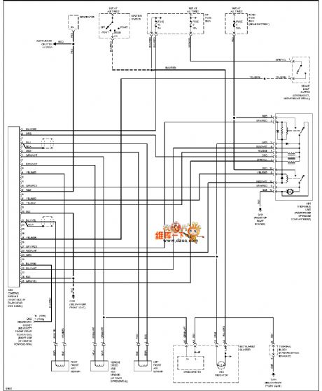
96 VOLVO 960 ABS circuit diagram
Published:2011/7/17 0:35:00 Author:nelly | Keyword: VOLVO, ABS
View full Circuit Diagram | Comments | Reading(792)
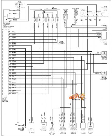
96 VOLVO motor performance circuit diagram(2.9L)
Published:2011/7/17 0:37:00 Author:nelly | Keyword: VOLVO, motor performance
View full Circuit Diagram | Comments | Reading(521)
MN6011 (VCR) infrared remote control launch circuit
Published:2011/7/17 8:04:00 Author:Christina | Keyword: VCR, infrared, remote control, launch circuit
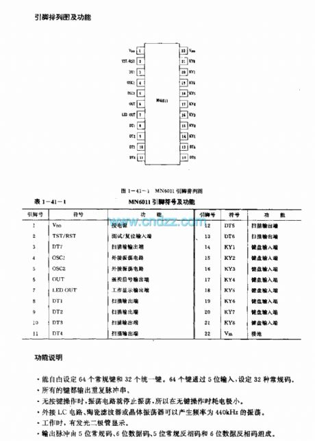

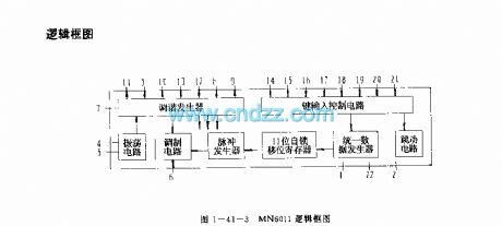
The MN6011 is designed as one kind of multi-function infrared remote control transmitter integrated circuit, and it can be used in the VCR. The internal circuit is composed of the oscilation circuit, the key input control circuit, the tuning generator, the pulse generator, the modulation circuit, the 11-bit self-locking shift register and the unified data generator.
Features
The CMOS technology very large scale integrated circuit (VLSI)The typical value of the power supply voltage is 3V.
Function description
It can set 64 conventional keys and 32 unified keys freely.All the keys can output the repetitive pulse sequence.When there is no key operation, the oscillation circuit will stop working.The external, LC circuit, ceramic filters and crystal oscillator can produce the 440kHz oscillating wave.The LED display.The output pulse is composed of the 5-bit conventional code, the 6-bit data code, the 5-bit conventional RP code and the 6-bit data RP code.
(View)
View full Circuit Diagram | Comments | Reading(1460)
Mazda 95TAURUS power window circuit diagram
Published:2011/7/16 23:36:00 Author:nelly | Keyword: Mazda, power window
View full Circuit Diagram | Comments | Reading(487)
MN6021 (TV) infrared remote control transmitter circuit
Published:2011/7/17 8:16:00 Author:Christina | Keyword: TV, infrared, remote control, transmitter
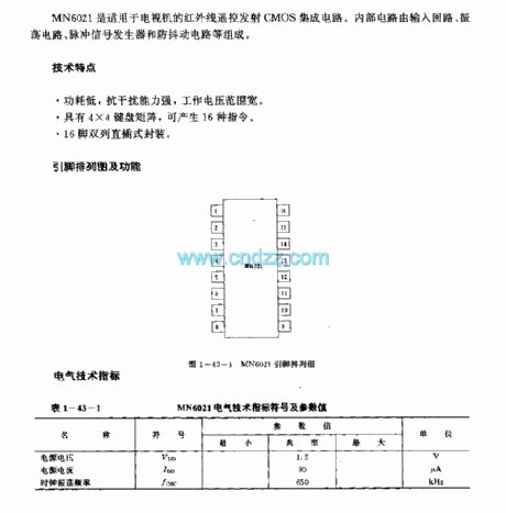
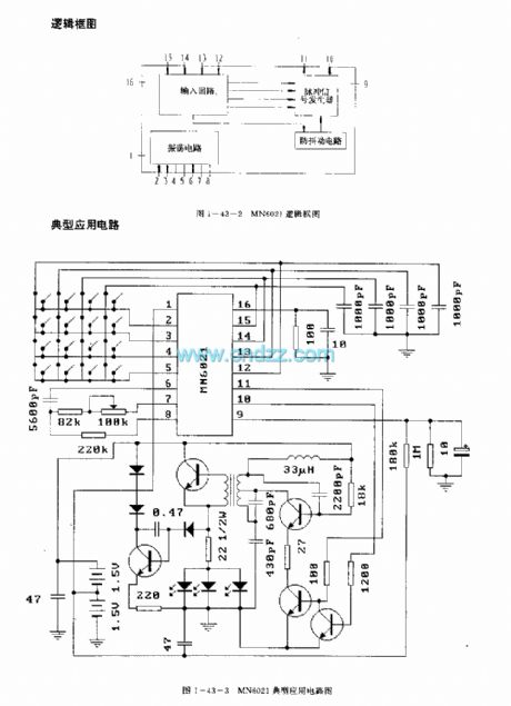
The MN6021 is designed as one kind of infrared remote control transmitter CMOS integrated circuit that can be used in the TV sets. The internal circuit is composed of the input loop, the oscillating circuit, pulse signal generator and the anti-jitter circuit.
Features
The low power consumption, strong anti-interference ability and wide operating voltage range .It has the 4X4 keyboard matrix to produce the 16 kinds of commands.16-pin dual-row DIP package.
(View)
View full Circuit Diagram | Comments | Reading(1922)
MN6014/S infrared remote control transmitter circuit
Published:2011/7/17 8:23:00 Author:Christina | Keyword: infrared, remote control, transmitter circuit
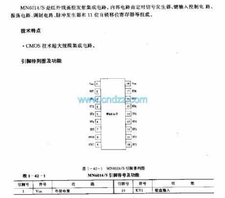
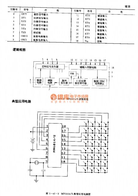

The MN6014/S is designed as one kind of infrared remote control transmitter circuit. The internal circuit is composed of the timing signal generator, the oscilation circuit, the key input control circuit, the tuning generator, the pulse generator, the modulation circuit, the 11-bit self-locking shift register.
Features
The CMOS technology very large scale integrated circuit (VLSI)
Function description
When there is no key operation, the oscillation circuit will stop working.
When you press the button several times, the output will be forbided.
It supplies 32 buttons.
(View)
View full Circuit Diagram | Comments | Reading(1268)
MN6930B(VCR)infrared remote control transmitter circuit
Published:2011/7/17 8:56:00 Author:Christina | Keyword: VCR, infrared, remote control, transmitter circuit
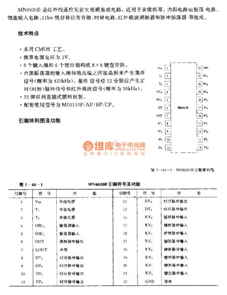
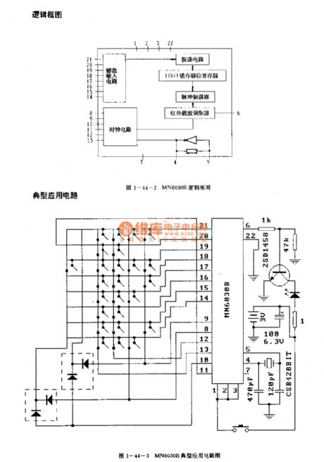
The MN6930B is designed as one kind of infrared remote control transmitter large scale integrated circuit, and it can be used in the VCR. The internal circuit is composed of the oscillating circuit, the keyboard input circuit, the 11-bit self-locking shift register, the clock circuit, the infrared wave-carrier modulator and the pulse oscillator.
Features
The CMOS technology.The recommend power supply voltage is 3V.The 8X6 keyboard matrix is composed of 8 type-in ports and 6 type-out ports.The crystal oscillator is connected between the input port and the output port of the internal oscillator to produce the benchmark signal (the frequency is 420kHz).The 22-pin dual-row DIP package.The matching models are M50110P/AP/BP/CP.
(View)
View full Circuit Diagram | Comments | Reading(1641)
MK5087 general infrared remote control transmitter circuit (dual-tone multiple-frequency signal generating circuit)
Published:2011/7/17 9:12:00 Author:Christina | Keyword: general, infrared, remote control, transmitter, dual-tone, multiple-frequency, signal, generating circuit

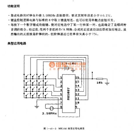
The MK5087 is designed as one kind of dual-tone multiple-frequency signal generating circuit that can be used in the radio transmission circuits. The internal circuit is composed of the clock oscillating circuit, the keyboard control logic circuit, the programmable frequency divider, the bass group D/A circuit, the treble group D/A circuit, the counting circuit and the squelch circuit.
Features
The voltage range of the power supply is 2.5-15V,The 16-pin dual-row DIP plastic package.
Function description
It can set 64 conventional keys and 32 unified keys freely.All the keys can output the repetitive pulse sequence.When there is no key operation, the oscillation circuit will stop working.The external, LC circuit, ceramic filters and crystal oscillator can produce the 440kHz oscillating wave.The LED display.The output pulse is composed of the 5-bit conventional code, the 6-bit data code, the 5-bit conventional RP code and the 6-bit data RP code.
(View)
View full Circuit Diagram | Comments | Reading(2095)
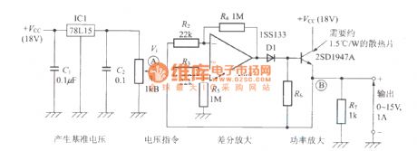
Voltage stabilization power supply circuit with the operational amplifier
Published:2011/7/16 5:56:00 Author:Christina | Keyword: Voltage stabilization, power supply, operational amplifier
View full Circuit Diagram | Comments | Reading(572)
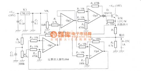
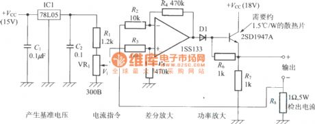
Voltage stabilizer, constant current circuit with the operational amplifier
Published:2011/7/16 5:55:00 Author:Christina | Keyword: Voltage stabilizer, constant current, operational amplifier
View full Circuit Diagram | Comments | Reading(1011)
Constant current power supply circuit with the operational amplifier
Published:2011/7/16 5:54:00 Author:Christina | Keyword: Constant current, power supply, operational amplifier
View full Circuit Diagram | Comments | Reading(918)
| Pages:1532/2234 At 2015211522152315241525152615271528152915301531153215331534153515361537153815391540Under 20 |
Circuit Categories
power supply circuit
Amplifier Circuit
Basic Circuit
LED and Light Circuit
Sensor Circuit
Signal Processing
Electrical Equipment Circuit
Control Circuit
Remote Control Circuit
A/D-D/A Converter Circuit
Audio Circuit
Measuring and Test Circuit
Communication Circuit
Computer-Related Circuit
555 Circuit
Automotive Circuit
Repairing Circuit